Transcription
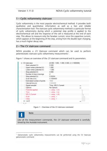
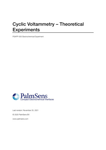
Version 1.11.0NOVA Cyclic voltammetry linear scan tutorial1 – Cyclic voltammetry linear scanCyclic voltammetry is the most popular electrochemical method. It provides bothqualitative and quantitative information as well as a fast and reliablecharacterization tool. The cyclic voltammetry linear scan method is a particularformat of cyclic voltammetry during which a linear potential sweep profile is appliedto the electrochemical cell and the response of the cell is measured continuously.This allows to measure both the faradic and the capacitive currents. Therefore, thisparticular form of cyclic voltammetry is well suited for monitoring changes in thedouble layer structure or electrochemical reactions characterized by fast electrontransfer kinetics.Two forms of cyclic voltammetry linear scan are supported in NOVA: Cyclic voltammetry linear scan: with scan rates up to 250 V/sCyclic voltammetry linear scan high speed: for scan rate over 250 V/sNoteBoth methods require at least the optional linear scan generator (either theSCANGEN or the SCAN250 module). For linear scan high speed, an additionalfast sampling ADC module is required (ADC750 or ADC10M).Depending on the hardware configuration of the instrument, the maximum scanrate will be different: SCANGEN or SCAN250: maximum scan rate – 250 V/sSCANGEN or SCAN250 with ADC750: maximum scan rate – 10 kV/sSCAN250 with ADC10M: maximum scan rate – 250 kV/s2 – The CV linear scan commandNOVA provides a CV linear scan command 1 which can be used to performpotentiostatic linear scan cyclic voltammetry measurements. The command islocated in the Measurement – cyclic and linear sweep voltammetry group ofcommands.Figure 1 shows an overview of the CV linear scan command and its parameters.The CV linear scan command requires the SCAN250 or SCANGEN module. This command is hiddenfrom view when the required modules are not specified in the hardware setup and the hardwarerelated profile is active.11 Page
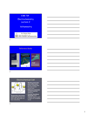
NOVA Cyclic Voltammetry linear scan tutorialFigure 1 – Overview of the CV linear scan commandThe CV linear scan command has the following parameters Start potential (V): defines the start potential, in Volts.Upper vertex potential (V): defines the upper vertex potential, in Volts. Theupper vertex potential must be larger than the lower vertex potential.Lower vertex potential (V): defines the lower vertex potential, in Volts. Thelower vertex potential must be smaller than the upper vertex potential.Initial direction: defines the initial direction of the scan (up/down).Number of start or vertex potential crossings: defines the number of timesthat the scan should cross the start or a vertex potential value in order tostop the measurement.Stop on start potential or vertex potential: defines whether the scanshould stop on the start potential or on a vertex potential 2.Potential interval (V): defines the length of the potential interval betweentwo consecutive data points used in the CV linear scan, in Volts. This valuemust be positive.Scan rate (V/s): defines the scan rate, in Volts per second 3.Signal sampler: defines the specific sampler used during the CV linear scanmeasurement. By default, Time, Potential applied and WE(1).Current aremeasured, but additional electrochemical signals can be added to thesampler. Moreover, the Scan signal, which provides the scan number, will beadded to the data.Options: defines the options used during the CV linear scan measurement(automatic current ranging and cutoffs).Stopping on the start potential is only possible when using the SCAN250 module.Because of the maximum sampling rate of the ADC164 module, the scan rate (in V/s) divided bythe potential step (in V) should always be lower than 12.000 s-1.232 Page
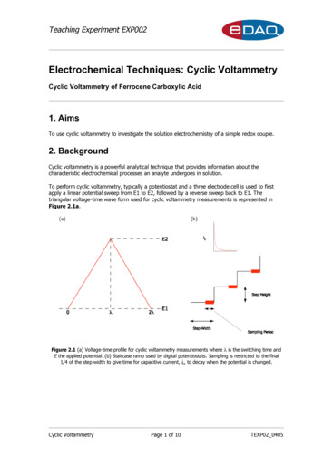
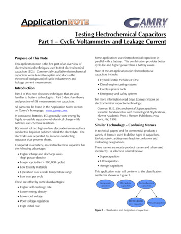
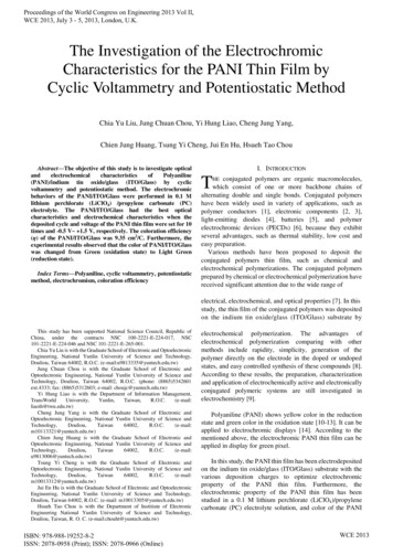
NOVA Cyclic voltammetry linear scan tutorialThe CV linear scan command in NOVA provides a flexible framework for thedefinition of the scan parameters. In a typical cyclic voltammetry experiment, it isassumed that the start and stop potentials should be the same. With NOVA, this isnot the case anymore, and the user is free to define any type a potential scan usingthe set of parameters available.3 – The CV linear scan high speed commandNOVA provides an additional CV linear scan high speed command 4 which can beused to perform potentiostatic linear scan cyclic voltammetry measurements at highscan rates. This command is located in the Measurement – cyclic and linear sweepvoltammetry group of commands.NoteThe CV linear scan high speed command is an Intermediate level command.Figure 2 shows an overview of the CV linear scan high speed command and itsparameters.Figure 2 – Overview of the CV linear scan high speed commandThe CV linear scan high speed command requires the SCAN250 or SCANGEN module incombination with the ADC10M or ADC750 module. This command is hidden from view when therequired modules are not specified in the hardware setup and the hardware related profile is active.43 Page
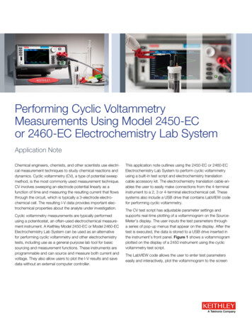
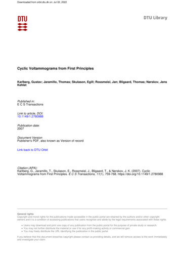
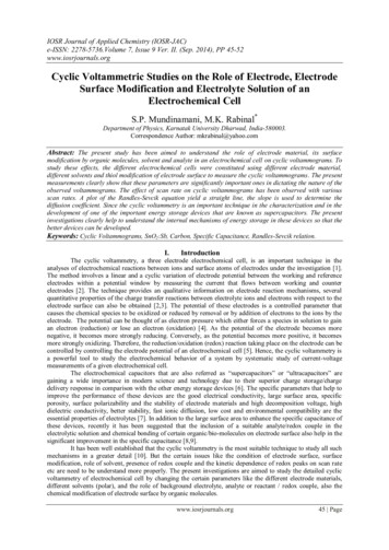
NOVA Cyclic Voltammetry linear scan tutorialThe CV linear scan high speed command has the following parameters: Start potential (V): defines the start potential, in Volts.Upper vertex potential (V): defines the upper vertex potential, in Volts. Theupper vertex potential must be larger than the lower vertex potential.Lower vertex potential (V): defines the lower vertex potential, in Volts. Thelower vertex potential must be smaller than the upper vertex potential.Initial direction: defines the initial direction of the scan (up/down).Number of start or vertex potential crossings: defines the number of timesthat the scan should cross the start or a vertex potential value in order tostop the measurement.Stop on start potential or vertex potential: defines whether the scanshould stop on the start potential or on a vertex potential 5.Potential interval (V): defines the length of the potential interval betweentwo consecutive data points used in the CV linear scan high speed, in Volts.This value must be positive.Scan rate (V/s): defines the scan rate, in Volts per second.ADC high speed settings: defines the acquisition settings for the fastsampling ADC (gain values, signals to sample, etc ). Since the fast samplingADC used to measure the data points during the scan is a double channelADC, only two electrochemical signals can be sampled (default:WE(1).Potential and WE(1).Current). An external signal can be measuredinstead of the WE(1).Current signal through the analog input on the frontpanel of the instrument (see Figure 3).Figure 3 – The ADC settings window can be used to define the gain value of the Current (orfor an external signal)5Stopping on the start potential is only possible when using the SCAN250 module.4 Page
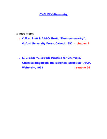
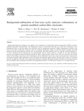
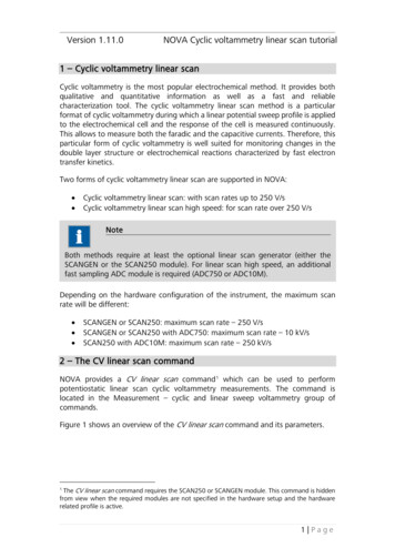
NOVA Cyclic voltammetry linear scan tutorial4 – Using the CV linear scan commandThe Autolab Cyclic voltammetry linear procedure provides a good example of theuse of the CV linear scan command (see Figure 4).Figure 4 – The Autolab linear scan procedureThe Autolab linear scan procedure performs a single scan, from 0 V to an uppervertex potential of 1 V, then to a lower vertex potential of -1 V and finally stoppingat the upper vertex potential, 1 V. The number of vertex potential crossings is three.The scan rate is 100 mV/s and the initial scan direction is upwards (i.e. from the startpotential to the upper vertex potential). Figure 5 shows the potential profile of thisexperiment.5 Page
NOVA Cyclic Voltammetry linear scan tutorialFigure 5 – The potential applied profile with the two stop crossings used in the AutolabLinear scan procedureThe CV linear scan command does not have a Stop potential value. It is possible tostop at the start potential 6 or at either one of the vertices.NoteDuring CV Linear scan, the current is monitored continuously. This allows torecord the capacitive current contribution during the cyclic voltammetrymeasurement. In CV staircase on the other hand, the measurement is performedat the end of a potential step. Therefore, the contribution from the capacitivecurrent is minimized.6SCAN250 module only.6 Page
NOVA Cyclic voltammetry linear scan tutorial4.1 – Changing the scan directionIn the CV linear scan command, the scan direction is defined by the settings of theInitial direction parameter. This parameter can be set to up or down. In the firstcase, the scan direction will be from the start potential to the upper vertex potential,while in the second situation, the scan direction will be the opposite (see Figure 6).Figure 6 – Changing the scan direction in the CV linear scan commandFigure 7 shows the applied potential profile used in the Autolab linear scanprocedure, when the initial direction is set to down.7 Page
NOVA Cyclic Voltammetry linear scan tutorialFigure 7 – The potential profile applied used in the Autolab linear scan procedure, with theinitial direction parameter set to down4.2 – Changing the number of scansThe number of scans in the CV linear scan command is defined by the number ofstart or vertex potential crossings. This unusual definition of the number of scanshas many advantages that will be illustrated in this tutorial.Depending on the settings, two start or vertex potential crossings are required forone cycle. This means that it is possible to define fractions of cycles during thepotential scan.Figure 8 shows the potential profile obtained with the Autolab linear scanprocedure, using four vertex potential crossings instead of three.8 Page
NOVA Cyclic voltammetry linear scan tutorialFigure 8 – The potential profile applied with four vertex potential crossingsNoteWhen the number of crossings is 1 and the linear scan generator module isinstructed to stop on a vertex potential, the resulting scan will correspond to alinear sweep voltammetry with linear scan.9 Page
NOVA Cyclic Voltammetry linear scan tutorial4.3 – Using a different stop pointThe SCAN250 module allows to stop the scan on the start potential or at one of thevertices 7. By choosing on which point to stop the scan, additional flexibility can bebuilt into the measurement (see Figure 9).Figure 9 – Setting the Stop on start potential or vertex potential property for measurementswith the SCAN250 moduleNoteThis option is only available for the SCAN250 module. The SCANGEN module canonly be stopped on a vertex potential.If the stop on vertex potential is used, it is possible to stop the scan on any of thevertices, depending on the number of vertex potential crossings and the scandirection.7The SCANGEN module can only stop on a vertex potential.10 P a g e
NOVA Cyclic voltammetry linear scan tutorialOn the other hand, if the start potential is used instead of the vertex potentials, it ispossible to build a different potential profile. Figure 10 shows the potential profileapplied during the linear scan procedure, using the SCAN250 module, when thestart potential is used to define the stop condition. In this example, the number ofstart or vertex potential crossings parameter has been set to two.Figure 10 – The potential profile generated by the SCAN250 module during the Autolablinear scan procedure, using the start potential crossings to define the number of scans5 – Using the CV linear scan high speed commandThe standard Autolab Cyclic voltammetry linear scan high speed procedure providesa good example of the use of the CV linear scan high speed command (see Figure11).11 P a g e
NOVA Cyclic Voltammetry linear scan tutorialFigure 11 – The Autolab High speed linear scan procedureThe standard High speed linear scan procedure performs a single scan, from 0 V toan upper vertex potential of 1 V, then to a lower vertex potential of -1 V and finallystopping at the upper vertex potential, 1 V. The number of vertex potential crossingsis three. The scan rate is 100 V/s and the initial scan direction is upwards (i.e. fromthe start potential to the upper vertex potential). Figure 12 shows the potentialprofile of this experiment.12 P a g e
NOVA Cyclic voltammetry linear scan tutorialFigure 12 – The potential profile generated during the High speed linear scan procedureThe options available in the CV linear scan command are also possible with the CVlinear scan high speed command. However, in order to use the CV linear scan highspeed command, a fast sampling ADC module (ADC750 or ADC10M) must be used.NoteBecause of the high sampling rate used during the CV linear scan high speedmeasurements it is not possible to display the measured data points in real-time.The measurement view will be updated at the end of the experiment.13 P a g e
NOVA Cyclic Voltammetry linear scan tutorialHardware specificationsThe linear scan generator module can be used to generate an analog triangularwaveform which can be used to perform linear scan cyclic voltammetry. The moduleis capable of generating the waveform with a maximum amplitude of 5 V. Thiswaveform is added on to the summation point of the Autolab which means that inpractice, the linear scan generator can be used to generate a scan with a 5 Vamplitude with respect to a 5 V offset produced by the Autolab.NotePlease refer to the Getting Started manual for more information about theAutolab PGSTAT and the summation point.Table 1 provides an overview of the linear scan generator modules.ModuleScan rangeVertex resolutionVertex accuracyOutput offsetMaximum scan rateMinimum scan rateSCAN250 5V0.15 mV2 mV 0.2 mV1 MV/s10 mV/sSCANGEN 5V2.5 mV5 mV 1 mV10 kV/s10 mV/sTable 1 – Overview of the specifications of the linear scan generator modulesWarningThe SCAN250 module is fitted with a vertex detection circuit which is used tosynchronize the reversal of the scan direction with the detection of the vertex. Atvery high scan rates, this circuit can cause the linear scan generator module tostop the scan at a potential value that does not match the experimentalparameters. This potential difference depends on the scan rate. The SCANGENmodule does not have this circuit and will stop when the vertex is reached. Athigh scan rates, this will cause the SCANGEN to overshoot the vertex value. Thepotential difference depends on the scan rate.14 P a g e
1 - Cyclic voltammetry linear scan Cyclic voltammetry is the most popular electrochemical method. It provides both qualitative and quantitative information as well as a fast and reliable characterization tool. The cyclic voltammetry linear scan method is a particular format of cyclic voltam metry during which a linear potential sweep profile .