Transcription
eCAADe 2019 – 13-15 September 2019, PortoA Spatial Reasoning Framework Based on Non-Manifold TopologyNicholas Mario Wardhana1, Wassim Jabi2, Aikaterini Chatzivasileiadi3, Nikoleta Petrova41,2,3,4Welsh School of Architecture, Cardiff University1,2,3,4{wardhanan jabiw chatzivasileiadia petrovan}@cardiff.ac.ukKeywords: Non-Manifold Topology, Topologic, Spatial Reasoning, PathfindingAbstractNon-Manifold Topology (NMT) has been previously proven to be an appropriate representation ofinterconnected architectural and spatial structures. This paper further explores the suitability of NMTfor spatial reasoning purposes. A literature survey is done to identify the necessary components of aspatial reasoning framework, and an adaptation of such framework based on NMT is presented. Thispaper also describes the implementation of an NMT-based spatial reasoning framework, its integrationinto the Topologic software library which the authors develop, as well as the implementation challenges.Finally, a study case on pathfinding on an NMT model, which has been generated from a BuildingInformation Modelling (BIM) structure, is presented and analysed.IntroductionThe concept of architectural space is essential in building design, representation, and reasoning (Ching2014). It has been argued that before the fabrication models are produced, buildings are typicallyperceived as a set of interconnected spaces (Curtis 1996). Seen from this perspective, spatial reasoningprovides information about the relationship among the spaces, the spatial information attached to everyindividual space, as well as with the objects and individuals occupying or surrounding the spaces. Suchinformation can be used as feedback to improve the building design, as well as to provide liveinformation to the user of the building e.g. in the presence of a hazardous situation.Building design and analysis workflows have traditionally used the concept of manifold topology,which centres around the idea of the boundaries of a three-dimensional entity separating the interiorfrom the exterior. In contrast to this, Non-Manifold Topology (NMT) offers a formal and consistenttopological framework which allows mixed-dimensional entities and junctions on the boundaries. This,therefore, allows internal subdivisions of a space separated by internal boundaries. As a consequence,the adjacency information among the spaces as well as other entities is explicitly stored in the buildingmodel and spatial queries can be conveniently performed. While NMT is commonly considered asdefects in current practice, it has been shown that NMT can better represent the concept ofinterconnected spaces and support spatial as well as topological queries (Aish and Pratap 2013; Jabi etal. 2017). There have been precedents in the use of NMT for spatial reasoning. For example, spatialreasoning on NMT has been used to perform social sustainability analysis on vernacular courtyardhouses and tall buildings (Al-Jokhadar 2018).Due to the inherent support for spatial queries, it is hypothesised that the use of NMT in spatialreasoning will enhance the current building design and analysis workflows. It is therefore crucial todevise a spatial reasoning framework that is built on top of the concept of NMT. This paper seeks tobuild a foundation to meet this aim and presents two objectives. Firstly, a review will be conducted onacademic papers as well as software libraries on spatial information typically used in the architecturaldesign processes, as well as existing spatial reasoning frameworks and algorithms. Secondly, a spatialreasoning framework based on the concept of Non-Manifold Topology will be presented andestablished from the review.
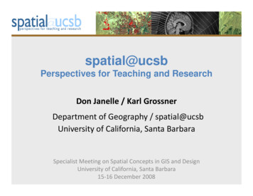
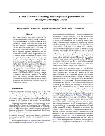
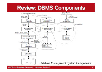
eCAADe 2019 – 13-15 September 2019, PortoNon-Manifold TopologyThe NMT framework presents a formal and consistent relationship among the multi-dimensionalconstituent entities. The authors’ earlier work (Chatzivasileiadi, Wardhana, et al. 2018) identified eightentities, namely (sorted in descending order based on the dimensional complexity) Cluster,CellComplex, Cell, Shell, Face, Wire, Edge, and Vertex. The hierarchy of these entities is shown inFigure 1. It is possible to navigate from one entity to another with higher or lower level ofdimensionality. Boolean operations can be used to modify NMT models, and the resulting model willretain the non-manifold property.Figure 1. The class hierarchy of the Non-Manifold Topology entitiesThe authors have developed a software library called Topologic (https://topologic.app/) on the basis ofNMT to facilitate the design and analysis of architectural models (Aish et al. 2018; Jabi et al. 2018).This library is implemented with a multi-layer architecture. The core package, written in C , containstopological classes and functionalities, including navigation queries. A higher-level layer is written onthe .NET platform on top of the core package and it serves as plugins to host applications, includingDynamo (Figure 2) and Grasshopper. These plugins wrap the classes and functionalities in the corepackage, as well as provide two-way mechanisms to convert an entity between the geometricrepresentations in the host applications and the topological representations in the library. In the earlierpublications (Chatzivasileiadi, Lannon, et al. 2018), the authors have presented workflows to use thislibrary in building performance and structural analyses.
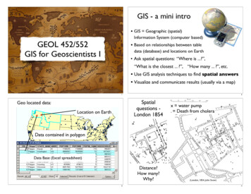
eCAADe 2019 – 13-15 September 2019, PortoFigure 2. Topologic running in DynamoLiterature ReviewIn order to design a spatial reasoning framework, a review on existing spatial data schemas and spatialreasoning frameworks is presented in this paper. Spatial data in this context refer to the located datarelated to every specific entity (Laurini and Thompson 1992). These data do not only refer to thelocation and orientation of the entity, but also non-location semantic data, such as the name and intendeduse of a room, as well as the number of occupants. Each of these data schemas and spatial reasoningframeworks may have seen considerable development, therefore it is beyond the scope of this paper topresent a detailed literature review.Spatial Data ModelsThis paper reviews four common data models and file formats from Building Information Modelling(BIM), Computer-Aided Design (CAD), and Geographical Information Systems (GIS), namely theIndustry Foundation Classes (IFC) (buildingSMART International Ltd 2013; International Organizationfor Standardization 2018), gbXML (Green Building XML (gbXML) Schema 2019), X3D (Web3DConsortium 2019), and CityGML (Gröger and Plümer 2012). These data models are analysed for theirsupport for three categories of data, namely the semantic attributes that can be attached to a spatialentity; the explicit topological relationships between two connected entities, either directly or indirectly;and the implicit topological relationships between two disjoint entities.IFCThe IFC is an open data model which is specifically designed to facilitate interoperability andcollaboration between the different teams in a BIM project. It was first conceptualised by a consortiumwhich was initiated by Autodesk in 1994, and it is now maintained by buildingSMART. The IFCschema provides geometric, topological, and application-specific attributes. As part of being anintegrated federated 3D model, IFC supports domain-specific attributes. These attributes are related tothe building controls, plumbing and fire protection, structural elements, structural activities, heating,ventilating, and air-conditioning (HVAC), electrical, architectural, and construction management.IFC supports explicit topological relationships between two entities of a boundary representation of anobject under the IfcTopologicalRepresentationItem superclass, which immediately consists of
eCAADe 2019 – 13-15 September 2019, PortoIfcConnectedFaceSet, IfcEdge, IfcFace, IfcFaceBound, IfcPath, IfcVertex, and IfcLoop. In IFC4, theimplicit topological relationships can be categorised into 6, namely Assignment, Association,Connection, Declaration, Decomposition, and Definition. Out of these 6 categories, the Connection andDecomposition relationships are relevant for spatial reasoning.CityGMLCityGML is the international standard for the 3D representation of an urban model, with support forgeometric, topological, and semantic attributes. It has seen applications such as in disaster handling,emergency responses, pathfinding, as well as energy analysis. In terms of semantic attributes, CityGMLprovides pre-defined object types which are categorised into one of the thematic modules, namely core(whose attributes inherited by other object types), relief, building, bridge, tunnel, transportation, waterbody, vegetation, city furniture, land use, groups, and generic (used for further extensions).The topology of the objects is described by the explicit, hierarchical connectivity between the geometricobjects. While surfaces need to be planar and 2-manifold, CityGML offers some support for nonmanifold topology in the form of Cell Complex. This feature enables modelling of a wall shared by twospaces. Two other yet related spatial relationships are the relativeToTerrain and relativeToWaterattributes, which respectively describe the position of an object relative to the ground surface or thewater surface. The relativeToTerrain attribute allows five values, namely entirelyAboveTerrain,substantiallyAboveTerrain, substantiallyAboveAndBelowTerrain, substantiallyBelowTerrain, andentirelyBelowTerrain. The relativeToWater attribute has similar values, replacing the keyword *Terrainwith WaterSurface. In addition, it has the temporarilyAboveAndBelowWaterSurface to representobjects affected by water tides.GBXMLGBXML is an XML schema that was designed to support data transfer in a BIM for further analysis. Ithas seen primary use for energy analysis, therefore the semantic attributes support this application,including variables related to heating, cooling, lighting, and space occupancy. GBXML also providesexplicit 3D topological relationship between the geometric entities in the form of a Campus, Building,Space, Surface, PolyLoop, and CartesianPoint. However, there does not seem to be support for implicitrelationship among the entities.X3DX3D is a standard to represent 3D computer graphics scenes and objects. This file format is a successorof the Virtual Reality Modeling Language (VRML), and provides classes and attributes to support awide array of application domains, including scientific visualisation, CAD and architecture, GIS,animation, 3D printing and 3D scanning, as well as Augmented/Virtual/Mixed Reality applications.While the classes and attributes provided in the standard are mostly for geometric, topological, andvisualization purposes, X3D provides Metadata classes to store custom attributes. Some furthermechanisms have been proposed to extend its capabilities to support semantic data exchange. Forexample, X3D can be paired with the Resource Description Framework (RDF) to provide sceneindependent ontology (Pittarello and De Faveri 2006).Spatial Reasoning FrameworksNumerous spatial reasoning frameworks have been proposed in the past and used in variousapplications. This section reviews spatial frameworks widely used in Architecture, as well as in otherareas including computer games and Geographical Information Systems (GIS). Identified groups offrameworks include the Region Connection Calculus (RCC) (Randell, Cui, and Cohn 1992), DirectionalReasoning Calculus (Frank 1992), space syntax (Hillier et al. 1976), dual graph (Boguslawski and Gold2016), pathfinding (Toll et al. 2018), sound propagation (Raghuvanshi and Snyder 2018), and roomlighting reasoning (Smith 2006).
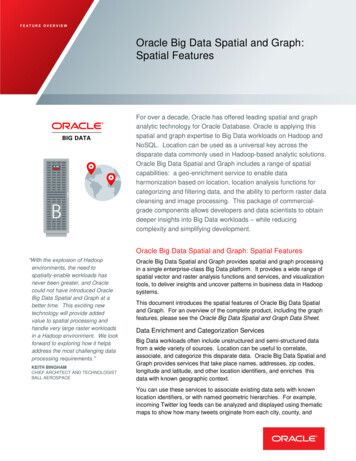
eCAADe 2019 – 13-15 September 2019, PortoRegion Connection CalculusRegion Connection Calculus (RCC) provides a formal topological connection between two entitiescalled regions. Its RCC-8 variant describes 8 fundamental relationships, namely Disconnected (DC),Externally Connected (EC), Equal (EQ), Partially Overlapping (PO), Tangential Proper Part (TPP),Tangential Proper Part Inverse (TPPi), Non-Tangential Proper Part (NTPP), and Non-Tangential ProperPart Inverse (NTPPi). These relationships are shown in Figure 3.Figure 3. The 8 configurations in Region Connection CalculusDirectional Reasoning CalculusTwo models have been defined by Frank (1992) regarding directional reasoning in 2D space: the conebased model and the projection-based model. The first one assumes that, given a point, a directionrelation between two arbitrary points on a 2D space can be represented by one of nine directions: East(E), West (W), South (S), North (N), North East (NE), North West (NW), South East (SE), South West(SW), and Identical (O) for the direction of the other point (Nam, S and Kim, I. 2015). The projectionbased model produces four directional partitions, e.g. north-west, north-east, south-east andsouthwest.An example of the two models is shown in Figure 4. Regarding 3D space and in the contextof building information modeling, a point-based approximation, such as the centre of mass, is normallyused. However, this rough approximation often results in unexpected results considering the user’sintuition (Borrmann and Beetz 2010). A few directional reasoning calculi exist for the 3D space andsome examples are the Rectangle Algebra (Balbiani et al. 1999) and the Cardinal Direction Calculs(CDC) (Goyal & Egenhofer 1997; Zhang et al. 2009).Figure 4. Frank’s (1992) cone-shaped (left) and projection-based (right) models of directional relationships between points(Borrmann and Beetz 2010)Space SyntaxSpace syntax focusses on the analysis and decoding of the connection between spaces and how differenttypes of connection shape human activity and social interactions. It is used as a theoretical but also atechnological tool by architects to represent and analyse space, contributing to the exploration of designideas for their proposals. Space syntax includes a set of analytical, quantitative and descriptive tools foranalysing the spatial formations in different contexts: buildings, cities, interior spaces or landscapes
eCAADe 2019 – 13-15 September 2019, Porto(Hillier and Hanson, 1984, Hillier, 1996). Metrics such as depth and integration are used to indicateproximity and accessibility.Dual GraphA graph is a data structure which is commonly used to explain the connectivity among several objects,and consists of vertices and edges. The dual graph is a type of graph which represents the dual structureof another topological entity. Typically, a cell and a face can be represented as a vertex at their centroids.The connection between adjacent cells or faces can then be represented as an edge connecting theircentroids. A variant of dual graph is the Dual Half-Edge (DHE) (Boguslawski et al. 2016), which candescribe the connection between the interior rooms of a building. It has seen applications in pathfindingand escape route computation.PathfindingThe primary objective of pathfinding is to find one or more paths between two locations in anenvironment by minimising a criterion, for example the distance or the number of vertices travelled. Itis an established research area in numerous disciplines, including Architecture, Robotics, and ComputerGames. The state-of-the-art pathfinding structures including the DHE (Boguslawski et al. 2016) and thenavigation mesh (van Toll et al. 2018), which is akin to a mesh or, topologically, a shell consisting ofconvex polygons overlaid on the planar surfaces in a 3D environment. Pathfinding algorithms aretypically based on graph search algorithms, such as the Dijkstra’s algorithm (Dijkstra 1959).Room Lighting ReasoningRoom lighting information can be used to determine the behaviour of a virtual agent. In stealth computergames, for example, an agent may prefer to move along the shaded areas to reduce her/his visibility andprovide protection from the opponents (Smith 2006).Sound propagationThe purpose of sound propagation simulation is to determine how acoustic waves travel in a virtualenvironment, thus providing realistic audio experience in Computer Graphics applications. A polygonsoup (i.e. a set of unordered polygons) remains commonly used in the latest techniques (Raghuvanshiand Snyder 2018). Similar to the lighting information, sound propagation can also be used for reasoningpurposes for an agent’s decision making (Smith 2006).A Non-Manifold Topology-Based Spatial Reasoning FrameworkBased on the review presented in the previous section, one disadvantage that is commonly shared byexisting representation is the use of 2D representations, either in the form of images or surfaces,although they can be positioned in a 3D environment. It can therefore be argued that there is a lack ofrepresentation of space in spatial reasoning mechanisms. Based on this finding, this research presents aunified NMT-based spatial reasoning framework. The benefit is mutual: not only does this researchextend the capability of the NMT framework, but also the capabilities of these spatial reasoningmechanisms will be enhanced by the spatial coverage and hierarchical consistency that NMT offers.Figure 5 shows an NMT-based spatial reasoning framework. On top of the NMT kernel, the SemanticKnowledge provide a mechanism to attach domain-independent semantic data to a topology, offeringflexibility to multiple application domains. The spatial reasoning framework layer uses both thetopological entities as well as the spatial knowledge to perform spatial analysis. Finally, the hostapplications (which, in the case of Topologic, are currently Dynamo and Grasshopper) provide a meansfor visualisation and interaction purposes.At the moment, Topologic provides partial support towards this framework, in particular with itsDictionary, Graph (as the generalisation of Dual Graph), and Pathfinding features. These, along with
eCAADe 2019 – 13-15 September 2019, Portothe implementation challenges will be thoroughly discussed in this section. More features will beimplemented and tested as future works.Figure 5. A spatial reasoning framework based on Non-Manifold TopologyDictionaryThe Dictionary system allows fully customisable semantic spatial attributes which are attached to theindividual topological entities. It is application-independent, thus offering flexibility for utilisation invarious applications. In this system, each topology is related to a hash map, which is a structure mappingunique keys to the values. Each of the key is a string, whereas currently the values can be an integer, areal number (a floating point), or a string. Support for other types of values, including a pointer toanother entity, will be added in the future. A Dictionary can be attached to a topology usingTopology.SetDictionary method, and queried from a topology using the Topology.Dictionary property.There is also partial support for Dictionary preservation across multiple operations, which keeps theDictionaries of constituent topologies survive until the end of a workflow.GraphThe Graph class in Topologic is implemented as an adjacency list, where in every vertex is mapped toa set of vertices it is connected to. This adjacency list is augmented with another list of edges, whichdescribes the connecting topology between every pair of vertices. The Graph class contains a DualGraph construction method from any type of topology, modifiers and queries related to the vertices andthe edges, methods to perform pathfinding, and visualisation methods via conversion into the hostgeometries.A dual graph can be generated from any kind of topology, taking into account the Aperture structures,such as windows and doors, in their presence. It should be noted that Topologic offers flexibility for anAperture to be of any topological type, and can equally be attached to any kind of topology. Theconstruction procedure is detailed in Table 1. It is also possible to get the topology of a Dual Graph asa Cluster, containing a set of edges and vertices.Table 1. Dual graph construction ruleType of input topologyVertexDual graph construction ruleA graph consisting of the vertex. All existing apertures are connectedbetween their centroids and the vertex.
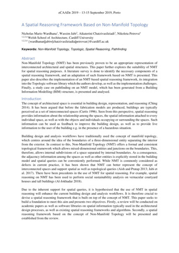
eCAADe 2019 – 13-15 September 2019, PortoEdgeWireFaceShellCellCellComplexClusterA graph consisting of the edge. All existing apertures are connectedbetween their centroids and the vertices of the edge.A graph consisting of the wire. All existing apertures are connectedbetween their centroids and the vertices of the wire.A graph connecting the face’s centroid and the centroids of the face’sbounding edges. All existing apertures are connected between theircentroids and the face’s centroid.A graph connecting the centroid of each faces of the shell to the centroidsof the face’s bounding edges. The edges are distinguished between thoseshared by the faces of the shell (thus connecting the vertices at thecentroids of two neighbouring faces) and those along the shell’s externalboundary, which are connected to only one face. All existing apertures areconnected between their centroids and the face’s centroid.A graph connecting the cell’s centroid and the centroids of the cell’sbounding faces. All existing apertures on the bounding faces areconnected between their centroids and the cell’s centroid.A graph connecting the centroid of each cells of the shell to the centroidsof the cell’s bounding faces. The faces are distinguished between thoseshared by the cells of the CellComplex (thus connecting the vertices at thecentroids of two neighbouring cells) and those along the CellComplex’sexternal boundary, which are connected to only one cell. All existingapertures on the faces are connected between their centroids and thebounded cell’s centroid.A graph will be created for every constituent member according to itstype, as written above. These graphs are then merged into the final graph.For pathfinding purposes, Topologic provides three methods, namely Graph.ShortestPath, which isbased on the Dijkstra’s algorithm (Dijkstra 1959); Graph.Path, which is based on greedy search; andGraph.AllPaths, which exhaustively searches for all possible paths between a pair of vertices, with anoptional time-limit. By default, these methods minimises the number of visited vertices. However, it ispossible to minimise another criterion by specifying the vertex or edge key in the Dictionary.Implementation ChallengesTwo implementation challenges are identified, and they will be addressed as future work. The first oneis related to the preservation of the dictionaries in the entire workflow. This is particularly challengingwhen the workflow involves Boolean operations, which may introduce new topological entities, andremove parts of the input entities. In these cases, there needs to be an intelligent rule to decide how thedictionaries survive, evolve, or are passed to the new entities. The second challenge is related toadapting the existing spatial framework into the mixed-dimensional NMT. A number of frameworks,for example the Space Syntax, were originally designed for a rasterised 2D floor plans. There have beensome modified frameworks to deal with 3D structures, for example the 3D isovist algorithm (Suleiman,Joliveau, and Favier 2013) and mixed-dimensional RCC (Izadi, Stock, and Guesgen 2017). However,to the best of the authors’ knowledge, the state-of-the-art pathfinding systems either use thetopologically 1D dual graph (Boguslawski and Gold 2016), or the topologically 2D navigation mesh(Toll et al. 2018). A more in-depth review and investigation will be needed in these areas.Study CaseTopological models have been used to perform pathfinding and navigation in the interior of a building,for example to assist the occupants when finding the way to a different part of the building, and for fireevacuation purposes (Jamali, Abdul Rahman, and Boguslawski 2016). The presented study case showshow to perform pathfinding on an NMT model. Three steps are involved in the workflow. Firstly, aBIM model is converted into a Topologic entity in Dynamo. Secondly, a dual graph is derived from the
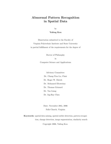
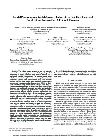
eCAADe 2019 – 13-15 September 2019, PortoTopologic entity. Thirdly, pathfinding is performed on the generated dual graph. This workflow runson Revit 2020, Dynamo 2.3.0 (developmental build) and Topologic 0.8.5, using the SampleArchitectural Project BIM model which is packaged with Autodesk Revit (Figure 6(a)).(a)(b)(c)(d)Figure 6. The pathfinding study case. (a) The original Sample Architectural Project BIM model in Revit. (b) The NMT cells,generated from the interior spaces of the BIM model, as shown in Dynamo. (c) The dual graph derived from the NMT model.(d) The shortest path between two vertices at different locations in the building.Converting a BIM Model into a Non-Manifold Topology ModelIn this step, the interior room spaces of the house are extracted from the BIM model as Dynamo solids.Topologic identifies these solids and converts them into topological cells. It should be noted thatbecause the walls of the house are also modelled as solids, there are gaps with varying thicknessseparating these room spaces. Due to these gaps, it is not possible to group the cells into a CellComplex.Instead, they are grouped as a cluster, which is shown (as Dynamo solids) in Figure 6(b).Deriving a Dual Graph from the NMT ModelThis step begins by generating dual graphs from the individual cells. This results in small graphs inwhich the vertices at the centroids of the cells connected to vertices at the centroids of their respectivebounding faces. While in an otherwise CellComplex-based model the graph would have just containeda single connected component, in this case, the smaller graphs are disjoint from each other due to thegaps between the cells. Therefore, a face matching procedure needs to be performed.To match the shared faces of two adjacent cells, the following rule is used: two faces are consideredneighbours if and only if:1) They are parallel (in other words, the angle between their normal vectors should approximately be0 or 180 within a small tolerance);2) Their centroids must not coincide each other (so as to prevent zero-length edges), but under amaximum value (with this model, the value of 500 unit is used); and,3) The perpendicular projection of one of the two faces onto the other one is entirely located within theother face.
eCAADe 2019 – 13-15 September 2019, PortoOnce every pair of neighbouring faces is identified, the vertices at their centroids are connected intoedges, and merged with the previously generated small graphs inside the room cells to yield the finalgraph, as shown in Figure 6(c). Here, the spheres represent the vertices of the final graph, while theblack lines correspond to the edges.Pathfinding on the Dual GraphOnce the dual graph is generated, pathfinding can then be performed between any pair of rooms in thebuilding. Figure 6(d) shows an example of finding a path between two extreme points, from the greensphere to the blue sphere, across the two storeys of the house, passing the white spheres on the boundingfaces (walls). This path can then be used to guide a virtual agent which move between the green andblue spheres, for example in an evacuation scenario.Conclusions and Future WorkThe NMT structure possesses a potential for utilisation as the foundation of a spatial reasoningframework. The inherent support for multi-dimensional entities and adjacency queries will beparticularly beneficial in this purpose. As part of the implementation of a spatial reasoning framework,the Topologic library provides a Dictionary system as well as the Graph class, which includespathfinding measures. The identified challenges include retaining the Dictionary system in a workflowinvolving Boolean operations, as well as adapting existing spatial reasoning frameworks for a multidimensional entity.Other forms of spatial reasoning framework will be added to Topologic. Further ahead, there is apotential for the creation of a Spatial Query Language (SQL) based on NMT, for example by extendingfrom the SPARQL query language (Prud’hommeaux and Seaborne 2008), to simplify the formulationof spatial queries, as well as to enhance the spatial query capabilities of the framework. The concept ofspatial reasoning can be used in other related areas. As an example, for digital fabrication, a rule-basedsystem can be deployed on the conceptual zero-thickness skeleton of a building to intelligently placeand trim solid building components, as well as to decide where to or not to deposit materials. Nonmanifold cells with no adjacency may require a different way to handle compared to another cell whichis heavily connected, and this can be conveniently determined in an NMT model.AcknowledgementsThis research project is funded by a Leverhulme Trust Research Project Grant (Grant No. RPG-2016016).ReferencesAish, Robert et al. 2018. “Topologic: Tools to Explore Architectural Topology.” In AAG 2018:Advances in Architectural Geometry 2018, Gothenburg, Sweden, 316–41.Aish, Robert, and Aparajit Pratap. 2013. “Spatial Information Modeling of Buildings Using NonManifold Topology with ASM and DesignScript.” In Advances in Architectural Geometry 2012,Vienna: Springer Vienna, 25–36.Al-Jokhadar, Amer. 2018. “Towards a Socio-Spatial Parametric Grammar for Sustainable TallResidential Buildings in Hot-Arid Regions Learning from the Vernacular Model of the MiddleEast and North Africa.” Cardiff University.Balbiani, P, Condotta, J-F and Farinas del Cerro, L 1999. ’A new tractable subclass of the rectanglealgebra’, Proc. of the 16th Int. Joint Conference on Artificial Intelligence (IJCAI-99).Boguslawski, Pawel, and Christopher Gold. 2016. “The Dual Half-Edge—A Topological Primal/DualData Structure and Construction Operators for Modelling and Manipulating Cell Complexes.”ISPRS International Journal of Geo-Information 5(2): 19.
eC
eCAADe 2019 - 13-15 September 2019, Porto A Spatial Reasoning Framework Based on Non-Manifold Topology Nicholas Mario Wardhana1, Wassim Jabi2, Aikaterini Chatzivasileiadi3, Nikoleta Petrova4 1,2,3,4 Welsh School of Architecture, Cardiff University 1,2,3,4 {wardhanan jabiw chatzivasileiadia petrovan}@cardiff.ac.uk Keywords: Non-Manifold Topology, Topologic, Spatial Reasoning, Pathfinding