Transcription
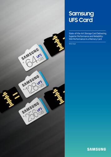
SamsungUFS CardState-of-the-Art Storage Card DeliveringSuperior Performance and Reliability:SSD Performance in a Memory CardWhite Paper1
Technology & Market Trends: UFS and UFS CardExecutive SummaryThis white paper explains how the features of Universal Flash Storage (UFS) card, including extreme performance, efficient power consumption,higher reliability, and exceptional user experiences for multi-processing environments, provide a massive improvement over the 20-year-old SDcard technology.The purpose of this paper is to encourage host OEMs to adopt the UFS card by providing details on the UFS card technology inside and financialadvantages.Technology & Market Trends: UFS and UFS CardJEDEC 1) is the most well-known international technology standard organizationfor DRAM, LPDDR, GDDR and NAND Flash-based storage, including UFS. Dueto its distinguished performance, UFS has been adopted as the primary storagesolution for the majority of smartphones today.To provide extremely high card storage performance, the industry definedand introduced removable card storage solutions based on UFS standards.On March 29, 2016, the JEDEC published standard UFS card v1.0 standardspecifications for removable cards that perform at speeds up to 600MB/sec. InJanuary 2018, JEDEC published UFS card v1.1 specifications that improve powerconsumption and stability.Figure 1. As small as the size of a fingernail, yet delivering SSD performance(1) The JEDEC (www.jedec.org) Solid State Technology Association is an independent semiconductor engineering tradeorganization and standardization body. JEDEC has more than 300 members, including some of the world's largestcomputer companies. Its scope includes the standardization of solid-state devices, and it develops standards forsemiconductor devices.To enhance interoperability between the host device and the UFS card, the UFSA (UFS Association),an industry association that promotes the use of UFS and UFS cards, released the first UFS CardCertification test specification (CTM v1.0) on April 7, 2016.For UFS card certification, the UFSA runs CTM compliance test specification workshops. InJuly 2016, the Samsung UFS card received the world’s first UFS card certification. To improveperformance and power consumption efficiency for mass production, Samsung enhanced its UFScard with a new CTM v1.3 UFSA certification in November 2017.Samsung is preparing to launch the world's first UFS card with several major OEM partners, andcontinues to build the UFS ecosystem through numerous industry collaborations.Figure 2. Samsung UFS card receiving the world'sfirst certification from the UFSA2
UFS Card vs. SD CardUFS Card vs. SD Card 1)SYNOPSIS Ⅱ/ⅡFinancial AdvantageIntellectualProperty Right:When the JEDEC published the UFS card standard in March 2016,Registered Community DesignDesign:Samsung held all of the design patents on the UFS card and declaredSerial No.:002988105-002Registration No.:002988105-002Owner:SAMSUNG ELECTRONICS CO., LTD.129,Samsung-ro, Yeongtong-gu, Suwon-siGyeonggi-do 443-742SÜDKOREAthem as a RAND solution to accelerate industry adoption. Samsungthen actively promoted UFS technology as a storage interfaceLocarno Classification: 14-02:Memory cards (part of-)solution, and distributed the royalty-free form factor unless necessaryFilling date:February 16, 2016for cross license purposes to protect the Samsung business.Priority:KR 30-2015-0057079 November12, 2015Application acceptedfor Registration:February 16, 2016This royalty-free approach provides a substantial financial benefitcompared to the SD card pricing structure with costly royalties borneby vendors.1. In this white paper, ‘SD card’ means SD UHS-I Card, as SD card is more commonlyknown and recognized in the market.ODA15-9779EUPublication ofRegistration:February 23, 2016Your Reference:Our Reference:54/SS00T00-002/EMPeriod of protection:5 years as of the application dateCountry:European CommunityMaximum period ofprotection:25 years, to be prolonged in 5 years stepsFigure 3. Samsung's patent on UFS card form factor and designPerformance AdvantageWhen comparing UFS card to SD card for its performance, sequential read performance, UFS card performs five times faster than the SD cardwhen it comes to booting and game loading times. In random read/write performance—i.e., several apps running in parallel or mirroring thecurrent smartphone environment, the UFS card shows benchmark performance improvements of 70 times faster than the SD card.SD CardSequentialUFS CardRandom500X540KX 20X 2.2100read speedX 7035K2002K90write speedread speed0.5Kwrite speedFigure 4. Measured performance: SD card vs. UFS card (Crystal Disk Benchmark)The superior UFS card performance is the result of several advanced features integrated into UFS technology, such as task queuing,asynchronous I/O protocol and fast I/O speeds of up to 600MB/sec. The SD card (UHS-I), on the other hand, uses a 20-year-old protocol ofsynchronous I/O, and can only reach a maximum speed of 104MB/sec.3
UFS Card vs. SD CardPower Consumption AdvantageThe command and data signals of an SD card require 3.3V at the initialization stage and 1.8V for read/write operation. The SD card uses 6 signalsof 1.8V (4 data signals, 1 command signal, 1 clock signal), which collectively consume a large amount of power.In contrast, the UFS card uses a lower 0.2V or 0.4V swing of one pair of differential signals, which dramatically reduces power consumption.SD Card: High Voltage SwingUFS Card: Low Voltage ATA3DATA3DATA30.4v / 0.2v3.3v 1.8vFigure 5. Slower signaling in SD card with 3.3v/1.8v vs. Faster signaling in UFS card with 0.4v/0.2vNot only the UFS card provides superior performance, it is also 10 times more energy efficient as it consumes less power than the SD card intransferring the same amount of data.Power consumptionPerformance: Max 104 MB/sPerformance: Max 600 MB/s (HS-G3)ActiveIdleUFS Card:Max 1.62WPower consumptionSD Card:Max 2.88WTimeActiveIdleTimeFigure 6. Maximum power consumption: SD card vs. UFS cardPower Reliability AdvantageSD CardUFS CardRMS (Root Mean Square)Power ConsumptionMAX 2.88W in 1,000 msec intervals Loose condition draws more power in a shorter timeinterval, which may lead to system level instabilityMAX 1.62W in 100 msec intervals 10x more strict condition to reduce variation in powerconsumption between devices 1.7x Longer battery life compared to the SD cardPeak Power ConsumptionSpecificaiton does not exist. Requires host device OEM to assign bigger power budgetfor covering wide range of peak power for various SDvendors and their various SD card productsPeak power spec exists as 5us intervals 500mA @3.3v VCC & 400mA @ 1.8v VCCQ) With more strict specification in power consumption fora device to meet, host device OEM can safely allocate PMICbased on peak power specificationsTable 1. Power consumption comparison between SD card and UFS card4
UFS Card vs. SD CardFor the SD card, the RMS power consumption specifications are managed in one-second period interval, and the fact that there is no peakpower consumption specifications can be an issue. Because of the long one second time intervals, it is more likely for the SD card to exceedthe allocated power budget set by the host device and could cause data loss or system instability. For this reason, host OEMs are challenged toallocate the precise power budget for the SD card slot, and/or they overcompensate by provisioning a much larger than needed power budget.For UFS cards, however, RMS power consumption specifications are managed in 100ms period intervals, and peak power consumption is definedbelow 500mA in 5us intervals, therefore providing superior performance with less of a power budget.Advanced Differential Signal AdvantageThe UFS card implements a state-of-the-art differential serial signal technology, while the SD card uses a single-ended signal pad. The UFS cardalso offers low voltage swing, differential signaling and fewer signals routing that result in reduced Electromagnetic Interference (EMI) than theSD card.Benefits of differential signaling in UFS card include: Resistance to EMI and CrosstalkIf EMI or crosstalk is introduced from outside the differential conductors, it is added equally to the inverted and non-inverted signals. Thus,the receiver circuitry greatly reduces the amplitude of the interference or crosstalk.The following figure compares EMI measurements of SD card to UFS card in the same physical environment. For the UFS Card, EMIs for allfrequency ranges are below the upper limit of the specification with much margin. For the SD card, however, satisfying the EMI spec is verydifficult, so EMIs are much worse than UFS Card as below Figure 7.SD CardUFS Card: EMI All Spec INLevel 50[dB(uv/m)]40Level 50[dB(uv/m)]EMI is very weak(very small margin)4030302020101000-103050100Frequency500EMI is very good(with much ure 7. EMI test results: SD card vs. UFS card Reduction to EMI and CrosstalkTwo signals in a differential pair create electromagnetic fields that are (ideally) equal in magnitude but, opposite in polarity. This is appliedin the UFS card and ensures that emissions from two conductors will largely cancel each other out. Better Signal-to-Noise RatioDifferential signals in a UFS card can use lower voltages and still maintain adequate signal-to-noise ratio (SNR) due to improved resistanceto noise, while the single-ended signals in a SD card require a steady high voltage to ensure adequate SNR. Less Complexity in Receiver CircuitryWith differential signals integrated into the UFS card, determining the logic state is simpler, just like comparing voltages of invertedand non-inverted signals. However, in the single-ended systems of SD cards, the receiver circuitry is more complicated, and the value ofreference voltage, as well as variations and tolerances, should be taken into consideration.5
UFS Card vs. SD CardAdvantages of Professional Physical/Link and Command LayerUFS card architecture is built on state-of-the-art industry proven protocols: M-PHY and UniPro of the Mobile Industry Processor Interface (MIPI)Alliance standard are adopted for the physical and link layers, and the SCSI command is adopted for the command layer.HighPerf.SerialInterfaceSPECIFICATIONSMIPI M-PHYDesignedforMobileLowPowerSPECIFICATIONSMIPI UniProUFS ingFigure 8. UFS Card is based on state-of-the-art MIPI and SCSI specs. M-PHY Physical LayerMIPI 1) M-PHY is a serial interface with ultra-high bandwidth and reliability, specifically developed for the high-demand performance andlow power requirements of mobile applications. The interface offers a low active power level and a near-zero idle power level for noteworthyreductions in device power consumption. UniPro Link LayerMIPI UniPro is a high-speed link technology for interconnecting integrated circuits in mobile and mobile-influenced electronics. UniProprovides detection and recovery from I/O errors on the hardware layers without requiring restarting from the host. SCSI Command LayerThe UFS standard adopts the well-known SCSI architecture model and advanced command protocols, including command queuing features.SCSI is widely used in many storage protocols such as USB3.0, SAS and more.By including the state-of-the-art MPHY physical layer, UniPro link layer and SCSI command layer, UFS card delivers high reliability,performance and power optimization, which are essential for in-vehicle and mobile systems.1) MIPI (Mobile Industry Processor Interface, www.mipi.org), is a global, open membership organization that develops interface specifications for the mobile ecosystem, including mobileinfluenced industries.6
UFS Card vs. SD CardAdvantage of Parallel Execution for Multi-ProcessingThe SD card uses an older, more primitive I/O interface protocol - synchronous I/O. This means, when the host sends a command to the SD card,it must wait for the completion of the command execution before sending the next command. This I/O method was designed for a single processmodel, which was the standard 20 years ago; however, in today’s multi-processing environment, this I/O architecture is neither appropriate noreffective.For example, if one application is using I/O operation in SD Card, then all other applications cannot start their I/O until the previous I/O operationis completed.Old Sync I/O Protocol (SD Card): one at a time very poor performanceHost (has to wait long time until device processing the data)R2W1Data1W3Data2Data3Figure 9. SD card style synchronous I/O protocol (one-at-a-time commands; host must wait for the completion of previous operations)Therefore, the SD card synchronous I/O interface may degrades the overall system throughputs, leading to a poor user experience. For instance,thumbnail photos shown in a smartphone photo gallery could appear as empty white screens for one or two seconds when the user scrolls thephoto gallary, or a video game could drop several video frames to catch up with the real-time game speed, making a moving object on the gamescreen appear unnatural.In contrast, the UFS host can send commands continuously, even while the UFS card is transferring data and processing previous commands.This allows an application to perform read-or-write operations while other applications simultaneously run without sluggish performance.Advanced Async I/O Protocol (UFS Card): TX/RX in parallel Ideal for Multi-processingHost (full execution)W1 R2Data1R3Data2Data1R4 W5 W6Data3Data4Data1R6Data5Data5Data6Figure 10. UFS card with advanced asynchronous queuing I/O protocol (read & write operations performed in parallel; multiple application can perform I/O for multiprocessingenvironments such as Android OS, Window OS, Apple iOS, etc.)Since read and write operations can be performed in parallel on the UFS card, total throughput given to the end-user is a summation of read andwrite performance. This cannot be achieved in an SD card due to its fundamental single protocol architecture.Furthermore, up to 32 commands can be queued in the UFS card. This means that a UFS card can perform out-of-order and parallel processing tomaximize the system throughput.7
System Architecture for UFS Card SupportSoft Migration From SD Card to UFS CardEven though the SD card I/O architecture and performance seems toUFS Card(11.0 x 15.0mm)be very poor in nowadays technical point of view, SD cards are found intoday's most mobile IT products. Therefore, from the moment the UFSmicroSD Card(11.0 x 15.0mm)card was designed, soft migration from the SD card to the UFS cardneeded to be considered. To support the migration, the overall outerdimension of the UFS card is determined to support a combo socket forboth microSD card and UFS card. To avoid any electrical problem withthe signal pins of the microSD card, the first row is left empty except VCCand GND, and the second row is used for the signal pins on the UFS card.Therefore, a host device can support both a microSD card and a UFScard using just one combo slot for a soft migration from microSD cardto UFS card. The reference combo socket is standardized in JEDEC as aSocket Mechanical Outline specification (SO-022A). Amphenol providesa combo socket that implements the SO-022A JEDEC standard.Figure 11. UFS Card Form Factor & Combo SocketSystem Architecture for UFS Card SupportFor the host system architect and designer, the following section provides an overview of how a UFS card supporting architecture can be designed.Combo SocketApplicationProcessorUFS I/FUFS I/F AP /w Dual UFS IFAP/CPU Supporting Two UFS InterfacesWith an AP/CPU supporting two UFS interfaces, one UFS interfaceInternalStoragecan be used for connecting the embedded UFS and the othereUFSUFS interface can be used for connecting the UFS card. If both amicroSD card and a UFS card need to be supported with a singleslot,the UFS card/microSD card combo socket can be used untilmicroSD card is phased out of the market.Figure 12. System Design for AP/CPU Supporting Two UFS InterfacesCombo Socket ApplicationProcessorUFS I/FeMMC I/FAP /w UFS IF & eMMCAP/CPU Supporting Only One UFS InterfaceMost AP/CPUs are likely to support the eMMC 1) interface until UFSInternalStoragereplaces eMMC completely. Therefore, the UFS interface can beeMMCused for connecting the UFS card, and the eMMC interface can beused for connecting eMMC as the embedded storage.1) eMMC stands for embedded MMC, which is one of the storage standards of JEDEC. eMMC has beenused in mobile products, including smartphones, for more than 10 years. In 2016, JEDEC defined theUFS standard to replace the role of eMMC, in order to provide a better performance and a lower powersolution.Figure 13. System Design for AP/CPU Supporting Only One UFS Interface Bridge chipCombo SocketApplicationProcessorAP/CPU Supporting USB interfaceIf the host device does not have any UFS interface in its AP/CPU,a Bridge Chip can be used to support the UFS card. Most AP/CPUsUSB 3.0USB to UFSsupport multiple USB interfaces, and a Bridge Chip for UFS-to/from-USB is available in the market. For example, SMI provides aBridge ChipUSB 3.1(5Gbps) to/from UFS Bridge Chip solution.Figure 14. System Design for AP/CPU Using Bridge Chip (UFS-to/from-USB)8
System Board Design GuidelinesSystem Board Design Guidelines for Supporting UFS CardThis section provides detailed information to board design engineers on designing system boards that support UFS cards. Socket Schematic for Host BoardThe following figure shows a recommended schematic for a UFS card, with all signal connections and passives needed. The purpose of theresistor connected on the CLK line is to reduce signal distortion and EMI by damping. The CLK as a toggle signal provides high power spectraldensity so the damping resistor can lower phenomena by reducing the slew rate of the CLK signal. The value can be selected between 0 and47 Ω depending on the system environment. From a practical standpoint, if the CLK trace is routed as a strip line or at inner layer, the seriesdamping resistance may be CCVCCQ2VCCQ2C/D0 47Ω (Optional)UFS CARDSOCKETUFS CARDC/DREF CLKREF CLKDIN TDIN TDIN CDIN CDOUT TDOUT TDOUT CDOUT CVSSVSSGNDGNDFigure 15. UFS Card Schematic with Socket Table 2 shows the Power Delivery Network (PDN) for supporting the UFS card. This PDN is designed to provide stable and uniform voltagesfor all devices. Commonly observed as a jitter or signal distortion, power noise, which is the voltage fluctuation of PDN, could significantlyaffect the timing and the digital signal integrity.1.8V(VCCQ2 )3.3V(VCC )De-cap Combination2.2uF 0.22uF4.7uF 0.22uFDC Resistance 1) 126 mΩ 126 mΩAC Impedance @ 20 MHz 2) 126 mΩ 126 mΩ1) Resistance from PMIC output to UFS socket SMT pad.2) Impedance from MLCC to UFS socket SMT pad, including the value of PCB tracesTable 2. Power Delivery Network (PDN)9
System Board Design Guidelines Signal Routing GuidelineTable 3 shows the allowable signal length depending on the UFShigh-speed gear.HS-Gear1/2HS-Gear3Signal line length 140 mm 90 mmLength difference between DP and DN 0.5 mm 0.5 mmTable 3. Max Signal Line Length on Board Socket Layout GuidelineA large pad size and small pad pitch will result in low differential impedance. To minimize differential impedance discontinuity (target100ohm), copper removal beneath the socket SMT pad (only for DIN T/C, DOUT T/C) is required, as shown in Figure 16.With a normal socket SMT pad dimension, copper removal of about 300um depth (considering PCB stack-up) is 7L8L9L10Figure 16. UFS Card Schematic with Socket Electrical Characteristics (Insertion/Return loss) for UFS Card SocketRequirement for UFS SocketRpin1) 18 mΩLpin 1) 2.32 nHSDD11 (@6GHz) -5.91 dBSDD21 (@6GHz) -2.25 dB1) Rpin and Lpin is partial loop value from SMT pad to Card Contact.Table 4. Recommended Electrical Characteristics for UFS Card Socket10OpeningDepth(300um)
Performance ComparisonPerformance Comparison between UFS Card and SD CardAlthough some software is not yet optimized for UFS card, the performance difference between SD card and UFS card is in evident across threekey usage scenarios. In identical testing environments, the UFS card outperformed the SD card by up to 3 times in loading time and by up to 4.5times in data transfer speeds.SD Card [Usage Scenario #1] Transferring Large File SizesUFS CardLoading Time(s)The same 4GB Adobe Photoshop file takes 54 seconds to loadfrom a SD card, while only 18 seconds to load from a UFS card.54.85The UFS card shows 3 times faster performance than the SD card in18.51this usage scenario.Usage Scenario #1. Loading of Photoshop File (4GB file size)] [Usage Scenario #2] Transferring Multiple FilesTransfer Time(s)As mobile devices continue to proliferate worldwide, consumershave a massive volume of files on their devices such as thousands29.59of high-quality photos and HD videos in the gallery. It took a6.58microSD card 29 seconds to transfer 1,000 files, but only 6 secondsfor a UFS card, which translates into 4.8 times better performancein a sequential data reading usage scenario.Usage Scenario #2. Transferring 1,000 filesIn January 2018, JEDEC UFS v3.0 announced support of HS-Gear 4 (12 Gbps per lane). By adopting the HS-G4 in the next version of UFS cardspecifications, the maximum interface performance of a UFS card will reach up to 1200MB/sec from current 600MB/sec, which meansperformance is soon to be doubled.ConclusionIn summary, the UFS card shows overwhelming performance enhancements, including 5 times higher sequential read performance and 70times higher random write performance, with lower power consumption than the SD card across benchmark applications. This outstandingimprovement comes from the advanced technologies included in the UFS card architecture: parallel read and write operations, queuing and outof-order execution to maximize performance, the allowance of mixed and interleaved data transfers so applications are not blocked by I/O ofother applications, lower power consumption by adopting power optimized physical layers and so on.All of these advanced UFS technologies are ideal for multi-processing environments, including Linux, Android OS, Window OS, and Apple iOS,which are used in most smartphones and tablets, as well as VR, AR, DRON, high-end DSLR cameras and other electronic devices. Currently, thereare many companies collaborating to develop the ecosystem for UFS card, providing solutions across UFS card sockets, UFS card controllers,USB-to-UFS Bridge Chips, file systems and more. Moreover, many device manufacturers are creating products that support UFS card.The industry leading performance of the UFS card is relevant for A/I and 5G applications as well.11
Annex A - UFS Top Level & System Architecture[A-1] UFS Top Level ArchitectureThe UFS specification adopts MIPI MPHY and UniPro specifications as its interconnection layer. MIPI is a standard organization defining interfacespec for mobile products. UPIU (UFS Protocol Interface Unit) and its communication protocol, UFS Transport Protocol (UTP), are definedon the UniPro. Some of SCSI commands are adopted as UFS commands. These commands are contained in a UPIU packet as payload to becommunicated between the UFS host and UFS storage device.UFS Application Layer (UAP)UFS Command Set (UCS)Device Manager(Query Request)UFS NativeCommand SetSimplified SCSICommand SetUDM SAPFutureExtension.UTP CMD SAPTaskManagerUTP TM SAPUFS Transport Protocol Layer (UTP)UIO SAPUIC SAPUFS Inter Connect Layer (UIC)MIPI UniProMIPI M-PHYFigure 17. UFS Top Level Architecture[A-2] UFS System ArchitectureThe embedded UFS card is connected with the UFS host with 4 types of pins (Reference Clk, Data-In, Data-Out, Reset) as shown below. SinceData-In, Data-Out is used in parallel, maximum throughput is the summation of maximum read performance and maximum write performance.UFS HostUFS DeviceDevice LevelManagingApplicationRST nControlDescriptorsConfigREF CLKDriverUFSDriverUFS HostControllerUFSHost RegUICDOUT IPIM-PHYSMDOUT cDIN tMIPIUniProSMDIN cFigure18. UFS System Architecture12
Annex B - UFS Card Mechanical Form Factor Standard[B-1] UFS Card Form Factor (MO-320A)The JEDEC published its UFS card protocol specification, JESD220-2, which is defined through the JC64.1 technical committee. The UFScard mechanical form factor specification, MO-320A, was defined through JC11 technical committee and published as well. This MO-320Aspecification defines detailed UFS card form factor, as well as detailed dimension information following the ASME Y14.5-2009 mechanicaldimension guidelines, which could enable any company to make the same UFS card with the same physical dimensions.This mechanical outline for the UFS card may be downloaded from the following link: f(JEDEC log-in required for downloading).Figure 19. 12-pin UFS Card (11x15) Top/Side ViewFigure 20. 12-pin UFS Card (0.91mm pitch) Bottom View13
Annex B - UFS Card Mechanical Form Factor Standard[B-2] UFS Socket Factor (SO-022)Amphenol, a company that specializes in socket design and development, created a host side socket that is aligned to the UFS card form factor,MO-320A. Amphenol’s host side socket design is published as a reference socket design aligned with UFS card form factor standard MO-320A.Socket design may vary depending on the allowed area by each smartphone OEM vendor and requirements, such as a combination of microSDand uSIM, etc. However, this standard socket (SO-022) can be used for the OEM vendor, for applications including VR, DRON, Note PC etc., whichis a relatively flexible space for the socket area. OEMs can purchase this standardized host side socket and develop their host products to easilysupport the UFS card, which can shorten the development and production time of their products.This reference combo socket for the UFS card may be downloaded from the following link: f (JEDEC log-in required for downloading)Figure 21. Reference Socket Mechanical Spec (SO-022) Aligned to UFS Card14
Annex C - Industry Collaboration: JEDEC, MIPI, UFSA[C-1] UFS Product Related Standard Organization: Role & CollaborationUFS is strongly supported by 3 global standard organizations: JEDEC, MIPI and UFSA. The following shows the scope and relationships amongstthose three standard organizations.JEDECUFSA eUFS sped UFS card spec UFS commandtest spec CTS spec &compliance test spec Marketing &Logo programMIPI MPHY spec UNIPRO spec CTS specFigure 22. Three International Standard Organizations Supporting UFS & UFS CardsJEDEC (www.jedec.org) defines industry standards related with memory and storage semiconductors, including DDR DRAM, LPDDR, GDDR, UFS,NVM future memory and more. JEDEC also provides storage standards for UFS and UFS cards, for embedded and external storage for mobile ITproducts.UFSA (UFS Association, www.ufsa.org) is an industry association designed to promote UFS. For interoperability between UFS host and UFSstorage devices, compliance test specifications (CTM v1.0) were published in April 2016, and are used for compliance certification programs forimproving interoperability between UFS cards and UFS hosts.MIPI (www.mipi.org) is an international standard organization that defines interfaces for mobile products. JEDEC adopted the MIPI MPHYspecification and the UniPro specification as the interconnection layer of UFS. By adopting physical and link layers from professional standardorganizations, UFS specification may improve more efficiently.15
Annex D - UFS Card Press Release Link[D-1] JEDEC UFS Card Publication Announcement- tandard March 30, 2016[D-2] UFSA CTM v1.0 Compliance Test Specification- ufs-card-standardization-by-jedec/ April 7, 2016[D-3] Samsung UFS Card: World’s First UFSA Certified Press Release (posted in UFSA)- ity/ July, 2016About Samsung Electronics Co., Ltd.Samsung inspires the world and shapes the future with transformative ideas and technologies. The company is redefining the worlds of TVs,smartphones, wearable devices, tablets, digital appliances, network systems, and memory, system LSI and LED solutions. For the latest news, please visitthe Samsung Newsroom at news.samsung.com.Copyright 2018 Samsung Electronics Co., Ltd. All rights reserved. Samsung is a registered trademark of Samsung Electronics Co., Ltd. Specifications and designs are subject tochange without notice. Nonmetric weights and measurements are approximate. All data were deemed correct at time of creation. Samsung is not liable for errors or omissions. Allbrand, product, service names and logos are trademarks and/or registered trademarks of their respective owners and are hereby recognized and acknowledged.Fio is a registered trademark of Fio Corporation. Intel is a trademark of Intel Corporation in the U.S. and/or other countries. Linux is a registered trademark of Linus Torvalds. PCIExpress and PCIe are registered trademarks of PCI-SIG. Toggle is a registered trademark of Toggle, Inc.Samsung Electronics Co., Ltd.129 Samsung-ro, Yeongtong-gu, Suwon-si, Gyeonggi-do 16677, Koreawww.samsung.com2018-05
The SD card (UHS-I), on the other hand, uses a 20-year-old protocol of synchronous I/O, and can only reach a maximum speed of 104MB/sec. 1. In this white paper, 'SD card' means SD UHS-I Card, as SD card is more commonly known and recognized in the market. Figure 3. Samsung's patent on UFS card form factor and design

