Transcription
RADIO TEST REPORTReport No: STS1704135F01Issued forTrackimo Inc450 Seventh Av. Suite 1408 New York, NY 10123 USAProduct Name:GPS TrackerBrand Name:N/AModel Name:Trkm010Series Model:N/AFCC ID:Test Standard:2AAI6-TRKM010FCC Part 22H and 24EAny reproduction of this document must be done in full. No single part of this document may be reproduced without permission from BZT, All Test Data Presented in this report is only applicable to presented Test sample.BZT Testing Technology Co., LtdAdd. : Buliding 17,Xinghua Road Xingwei industrial Park Fuyong,Baoan District,Shenzhen,Guangdong,China
2 of 65Report No.: STS1704135F01TEST RESULT CERTIFICATIONApplicant’s name . : Trackimo IncAddress . : 450 Seventh Av. Suite 1408 New York, NY 10123 USAManufacture's Name . : HUIZHOU QIAOWEI INTELLIGENT OVERSEAS CO.,LTDB2 building, ELing phase 2,wuyi village, chenjiang steet, gaoxin disAddress . : trict ,Huizhou city, Guangdong Province, ChinaProduct name . : GPS TrackerBrand name . : N/AModel and/or type reference . : Trkm010Standards . : FCC Part 22H and 24ETest procedure . ANSI/TIA:603-D (2010)This device described above has been tested by STS and the test results show that the equipmentunder test (EUT) is in compliance with the FCC requirements. And it is applicable only to the testedsample identified in the report.This report shall not be reproduced except in full, without the written approval of STS, this documentmay be altered or revised by STS, personal only, and shall be noted in the revision of the document.Date of Test . :17 Apr.Date of performance of tests .: 2017 06 May. 201709 May.Date of Issue .: 2017Test Result .Pass :Testing Engineer:(Leo li)Technical Manager:(Tony liu)Authorized Signatory :(Vita Li)
3 of 65Report No.: STS1704135F01TABLE OF CONTENTS1 INTRODUCTIONPage61.1 TEST FACTORY61.2 MEASUREMENT UNCERTAINTY62 PRODUCT INFORMATION73 TEST CONFIGURATION OF EQUIPMENT UNDER TEST84 MEASUREMENT INSTRUMENTS95 TEST ITEMS105.1 CONDUCTED OUTPUT POWER105.2 PEAK TO AVERAGE RATIO115.3 TRANSMITTER RADIATED POWER (EIRP/ERP)125.4 OCCUPIED BANDWIDTH135.5 FREQUENCY STABILITY145.6 SPURIOUS EMISSIONS AT ANTENNA TERMINALS155.7 BAND EDGE165.8 FIELD STRENGTH OF SPURIOUS RADIATION MEASUREMENT17APPENDIX ATESTRESULT19A1CONDUCTED OUTPUT POWER19A2 PEAK-TO-AVERAGE RADIO22A3 TRANSMITTER RADIATED POWER (EIRP/ERP)23A4 OCCUPIED BANDWIDTH(99% OCCUPIED BANDWIDTH/26DB BANDWIDTH) 26A5 FREQUENCY STABILITY36A6 SPURIOUS EMISSIONS AT ANTENNA TERMINALS41A7 BAND EDGE49A8 FIELD STRENGTH OF SPURIOUS RADIATION MEASUREMENT57APPENDIX BPHOTOS OF TEST SETUP65
4 of 65Report No.: STS1704135F01Revision HistoryRev.Issue DateReport NO.Effect PageContents0009 May. 2017STS1704135F01ALLInitial Issue
5 of 65Report No.: STS1704135F01SUMMARY OF TEST RESULTSTest procedures according to the technical standards:The radiated emission testing was performed according to the procedures of ANSI/TIA-603-D:2010,KDB 971168 D01 v02r02 and KDB 648474 D03 v01r04FCC RulesTest DescriptionTest LimitTest Result2.1049Conducted OutputPowerReporting OnlyPASSPeak-to-AverageRatio 13 dBPASS2.014624.2322.1046Effective Radiated Pow-22.913er/Equivalent Isotropic24.232Radiated Power 7 Watts max. ERP(Part 22) 2 Watts max. EIRP(Part 24)PASS2.104922.917Occupied BandwidthReporting OnlyPASS24.2382.105522.355 2.5 ppm (Part 22)Frequency 8Emission must remain in bandPASS(Part 24)Spurious Emission atAntenna TerminalsField Strength of SpuriousRadiation 43 10log10(P[Watts])PASS 43 10log10(P[Watts])PASS 43 10log10(P[Watts])PASS2.105122.91724.238Band EdgeReference
6 of 65Report No.: STS1704135F011 INTRODUCTION1.1 TEST FACTORYBZT Testing Technology Co., Ltd.Add. : Buliding 17,Xinghua Road Xingwei industrial Park Fuyong,Baoan District,Shenzhen,Guangdong,ChinaFCC Registration No.: 7017331.2 MEASUREMENT UNCERTAINTYThe measurement uncertainties shown below were calculated in accordance with the requirementsofANSI C63.4-2014. All measurement uncertainty values are shown with a coverage factor of k 2toindicate a 95% level of confidence. The measurement data shown herein meets or exceeds theUCISPRmeasurement uncertainty values specified in CISPR 16-4-2 and, thus, can be compareddirectly tospecified limits to determine compliance.。No.ItemUncertainty1RF power,conducted 0.70dB2Spurious emissions,conducted 1.19dB5All emissions,radiated( 1G) 30MHz-200MHz 2.83dB6All emissions,radiated( 1G) 200MHz-1000MHz 2.94dB7All emissions,radiated( 1G) 3.03dB8Temperature 0.5 C9Humidity 2%
7 of 65Report No.: STS1704135F012 PRODUCT INFORMATIONProduct Designation:GPS TrackerHardware version number:0.2Software version number:V7FCC ID:2AAI6-TRKM010GSM/GPRS/EDGE:850: 824.2 MHz 848.8 MHzTx Frequency:1900: 1850.2 MHz 1909.8MHzWCDMA:Band V: 826.4 MHz 846.6 MHzBand II: 1852.4 MHz 1907.6 MHzGSM/GPRS/EDGE:850: 869.2 MHz 893.8 MHzRx Frequency:1900: 1930.2 MHz 1989.8 MHzWCDMA:Band V: 871.4 MHz 891.6 MHzMax RF Output Power:Type of Emission:Band II: 1932.4 MHz 1987.6 dBmWCDMABand V:22.43dBm,WCDMA Band II:22.11dBmGSM(850): 318KGXW; GSM(1900): 320KGXWGPRS(850): 315KGXW; GPRS(1900): 321KGXWEDGE(850): 321KG7W; EDGE(1900): 317KG7WWCDMA850: 4M69F9WWCDMA1900: 4M69F9WSIM Card:SIM 1 and SIM 2 is a chipset unit and tested as singlechipset,SIM 1 is used to testedAntenna:PIFA AntennaAntenna gain:GSM 850: 0.23dBi ,PCS 1900: 0.23dBiWCDMA 850: 1.34dBi, WCDMA1900:1.34dBiBattery parameter:Capacity: 600mAh, Rated Voltage: 3.7VGPRS/EDGE Class:Multi-Class12Extreme Vol. Limits:DC3.4 V to 4.2 V (Nominal DC3.7V )Extreme Temp. Tolerance:-30 to 50 ** Note: The High Voltage 4.2 V and Low Voltage 3.4 V was declared by manufacturer, TheEUT couldn’t be operate normally with higher or lower voltage.
8 of 65Report No.: STS1704135F013 TEST CONFIGURATION OF EQUIPMENT UNDER TESTAntenna port conducted and radiated test items were performed according to KDB 971168 D01 PowerMeas. License Digital Systems with maximum output power.Radiated measurements were performed with rotating EUT in different three orthogonal test planes tofind the maximum emission.Radiated emissions were investigated as following frequency range:1. 30 MHz to 10th harmonic for GSM850 and WCDMA Band V.2. 30 MHz to 10th harmonic for WCDMA Band IV.3. 30 MHz to 10th harmonic for GSM1900 and WCDMA Band II.All modes and data rates and positions were investigated.Test modes are chosen to be reported as the worst case configuration below:TEST MODESBANDRADIATED TCSCONDUCTED TCSGSM 850GSM LINKGPRS/EDGE CLASS 12 LINKGSM LINKGPRS/EDGE CLASS 12 LINKGSM 1900GSM LINKGPRS/EDGE CLASS 12 LINKGSM LINKGPRS/EDGE CLASS 12 LINKWCDMA BAND VRMC 12.2KBPS LINKRMC 12.2KBPS LINKWCDMA BAND IIRMC 12.2KBPS LINKRMC 12.2KBPS LINK
9 of 65Report No.: STS1704135F014 MEASUREMENT INSTRUMENTSLast CalibraCalibrated UntiltionKind of EquipmentManufacturerType No.Serial No.Spectrum 2Signal 2Test tion munication TesterR&SCMU2001120122016.10.232017.10.22Test ReceiverR&SESCI1020862016.10.232017.10.22Bilog CBL6111D346782014.11.242017.11.23Horn AntennaSchwarzbeckBBHA 9120D9120D-13432015.03.052018.03.04Horn Antenna(Calibration antenna)SchwarzbeckBBHA 9120D9120D-13432015.03.052018.03.04MXA SIGNAL 2Double Ridge Horn 2017.10.22Low frequency cableN/AR01N/ANCRNCRHigh frequency cableSCHWARZBECKAK9515HSN-96286/96287NCRNCRVector signal .10.22Power amplifierDESAYZHL-42W96382016.10.232017.10.22Band Reject 0.232017.10.22Band Reject 32017.10.22Band Reject 0.232017.10.22Band Reject 232017.10.22Band Reject 232017.10.22Highpass .22Bilog Antenna(Calibration antenna)Equipment with a calibration date of “NCR” shown in this list was not used to make direct calibratedmeasurements.
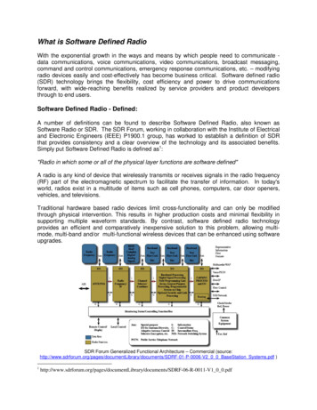
10 of 65Report No.: STS1704135F015 TEST ITEMS5.1 CONDUCTED OUTPUT POWERTest overviewA system simulator was used to establish communication with the EUT. Its parameters were set toenforce EUT transmitting at the maximum power. The measured power in the radio frequency on thetransmitter output terminals shall be reported.Test procedures1. The transmitter output port was connected to the system simulator.2. Set eut at maximum power through the system simulator.3. Select lowest, middle, and highest channels for each band and different modulation.4. Measure and record the power level from the system simulator.Test setup
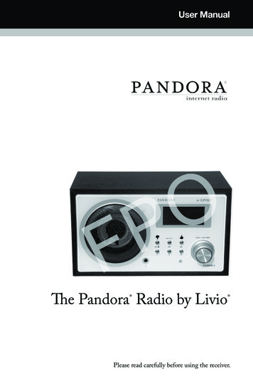
11 of 65Report No.: STS1704135F015.2 PEAK TO AVERAGE RATIOTEST OVERVIEWAccording to §24.232(d), power measurements for transmissions by stations authorized under thissection may be made either in accordance with a commission-approved average power techniqueor in compliance with paragraph (e) of this section. In both instances, equipment employed must beauthorized in accordance with the provisions of §24.51. In measuring transmissions in this bandusing an average power technique, the peak-to-average ratio (PAR) of the transmission may notexceed 13 db.TEST PROCEDURES1. The testing follows fcckdb 971168 v02r02 section2. The eut was connected to the and peak and av system simulator& spectrum analysis reads3. Select lowest, middle, and highest channels for each band and different modulation.4. Set the test probe and measure average power of the spectrum analysisTEST SETUP
12 of 65Report No.: STS1704135F015.3 TRANSMITTER RADIATED POWER (EIRP/ERP)TEST OVERVIEWEffective Radiated Power (ERP) and Equivalent Isotropic Radiated Power (EIRP) measurements areperformed using the substitution method described in ANSI/TIA-603-D-2010 with the EUT transmittinginto an integral antenna. Measurements on signals operating below 1GHz are performed using verticallypolarized tuned dipole antennas. Measurements on signals operating above 1GHz are performed usingvertically polarized broadband horn antennas. All measurements are performed as RMS average measurements while the EUT is operating at maximum power, and at the appropriate frequencies.TEST PROCEDURE1. The testing follows FCC KDB 971168 D01 Section 5.2.1. (for CDMA/WCDMA),Section 5.2.2 (for GSM/GPRS/EDGE) and ANSI / TIA-603-D-2010 Section 2.2.17.2. The transmitter was placed on a wooden turntable, and it was transmitting into a non-radiating loadwhich was also placed on the turntable.3. The measurement antenna was placed at a distance of 3 meters from the EUT. During the tests, theantenna height and polarization as well as EUT azimuth were varied in order to identifythe maximum level of emissions from the EUT. The test was performed by placing the EUT on3-orthogonal axis.4. The frequency range up to tenth harmonic of the fundamental frequency was investigated.5. Remove the EUT and replace it with substitution antenna. A signal generator was connected to thesubstitution antenna by a nonradiating cable. The absolute levels of the spurious emissionswere measured by the substitution.6. Effective Isotropic Radiated Power (EIRP) was measured by substitution method accordingto TIA/EIA-603-D. The EUT was replaced by the substitution antenna at same location, andthen a known power from S.G. was applied into the dipole antenna through a Tx cable, andthen recorded the maximum Analyzer reading through raised and lowered the test antenna.The correction factor (in dB) S.G. - Tx Cable loss Substitution antenna gain - Analyzerreading. Then the EUT's EIRP/ERP was calculated with the correction factor,ERP/EIRP P.SG GT – LCERP/EIRP effective or equivalent radiated power, respectively (expressed in the same units as PMeas, typically dBW or dBm);PMeas(PK) measured transmitter output power or PSD, in dBm or dBW;GT gain of the transmitting antenna, in dBd (ERP) or dBi (EIRP);LC signal attenuation in the connecting cable between the transmitter and antenna, in dB.
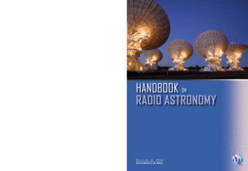
13 of 65Report No.: STS1704135F015.4 OCCUPIED BANDWIDTHTEST OVERVIEWThe occupied bandwidth, that is the frequency bandwidth such that, below its lower and above its upperfrequency limits, the mean powers radiated are each equal to 0.5 percent of the total mean power radiated by a given emission shall be measured.The 26 dB emission bandwidth is defined as the frequency range between two points, one above andone below the carrier frequency, at which the spectral density of the emission is attenuated 26 dBbelow the maximum in-band spectral density of the modulated signal. Spectral density (power per unitbandwidth) is to be measured with a detector of resolution bandwidth equal to approximately 1.0% ofthe emission bandwidth.All modes of operation were investigated and the worst case configuration results are reported in thissection.TEST PROCEDURE1. The signal analyzer’s automatic bandwidth measurement capability was used to perform the 99%occupied bandwidth and the 26dB bandwidth. The bandwidth measurement was not influenced byany intermediate power nulls in the fundamental emission.2. RBW 1 – 5% of the expected OBW3. VBW 3 x RBW4. Detector Peak5. Trace mode max hold6. Sweep auto couple7.The trace was allowed to stabilize8. If necessary, steps 2 – 7 were repeated after changing the RBW such that it would be within1 – 5% of the 99% occupied bandwidth observed in Step 7TEST SETUP
14 of 65Report No.: STS1704135F015.5 FREQUENCY STABILITYTest OverviewFrequency stability testing is performed in accordance with the guidelines of ANSI/TIA-603-D-2010. Thefrequency stability of the transmitter is measured by:a.) Temperature: The temperature is varied from -30 C to 50 C in 10 C increments using anenvironmental chamber.b.) Primary Supply Voltage: The primary supply voltage is varied from 85% to 115% of the nominalvalue for non hand-carried battery and AC powered equipment. For hand-carried, battery-poweredequipment, primary supply voltage is reduced to the battery operating end point which shall bespecified by the manufacturer.For Part 22, the frequency stability of the transmitter shall be maintained within 0.00025% ( 2.5ppm) of the center frequency. For Part 24 the frequency stability shall be sufficient to ensure thatthe fundamental emission stays within the authorized frequency block.Test ProcedureTemperature Variation1. The testing follows fcckdb 971168 D01 section 9.02. The EUT was set up in the thermal chamber and connected with the system simulator.3. With power OFF, the temperature was decreased to -30 C and the EUT was stabilized before testing.Power was applied and the maximum change in frequency was recorded within one minute.4. With power OFF, the temperature was raised in 10 C steps up to 50 C. The EUT was stabilized ateach step for at least half an hour. Power was applied and the maximum frequency change was recorded within one minute.Voltage Variation1. The testing follows FCC KDB 971168 D01 Section 9.0.2. The EUT was placed in a temperature chamber at 25 5 C and connected with the system simulator.3. The power supply voltage to the EUT was varied from 85% to 115% of the nominal value measured atthe input to the EUT.4. The variation in frequency was measured for the worst case.TEST SETUP
15 of 65Report No.: STS1704135F015.6 SPURIOUS EMISSIONS AT ANTENNA TERMINALSTest OverviewThe power of any emission outside of the authorized operating frequency ranges must be lower thanthe transmitter power (P) by a factor of at least 43 10 log (P) dB.It is measured by means of a calibrated spectrum analyzer and scanned from 30 MHz up to afrequency including its 10th harmonic.Test procedure1. The testing FCC KDB 971168 D01 v02r02 Section 6.0. and ANSI/TIA-603-D-2010-Section 2.2.13.2(d)2. The EUT was connected to the spectrum analyzer and system simulator via a power divider.3. The RF output of EUT was connected to the spectrum analyzer by an RF cable andattenuator. The path loss was compensated to the results for each measurement.4. The middle channel for the highest RF power within the transmitting frequency wasmeasured.5. The conducted spurious emission for the whole frequency range was taken.6. The RF fundamental frequency should be excluded against the limit line in the operatingfrequency band.7. The limit line is derived from 43 10log(P) dB below the transmitter power P(Watts) P(W) - [43 10log(P)] (dB) [30 10log(P)] (dBm) - [43 10log(P)] (dB) -13dBm.Test Setup
16 of 65Report No.: STS1704135F015.7 BAND EDGEOVERVIEWAll out of band emissions are measured with a spectrum analyzer connected to the antenna terminal ofthe EUT while the EUT is operating at maximum power, and at the appropriate frequencies. All datarates were investigated to determine the worst case configuration. All modes of operation were investigated and the worst case configuration results are reported in this section.The minimum permissible attenuation level of any spurious emission is 43 log10(P[Watts]), where Pis the transmitter power in Watts.TEST PROCEDURE1.The testing FCC KDB 971168 D01 v02r02 Section 6.0. and ANSI/TIA-603-D-2010-Section 2.2.13.2(d)2. Start and stop frequency were set such that the band edge would be placed in the center of the Plot.3. The EUT was connected to the spectrum analyzer and system simulator via a power divider.4. The RF output of EUT was connected to the spectrum analyzer by an RF cable and attenuator.The path loss was compensated to the results for each measurement.5. The band edges of low and high channels for the highest RF powers were measured.6.The RF fundamental frequency should be excluded against the limit line in the operatingfrequency band.7.The limit line is derived from 43 10log(P) dB below the transmitter power P(Watts) P(W) - [43 10log(P) ] (dB) [30 10log(P)] (dBm) - [43 10log(P) ] (dB) -13dBm.TEST SETUP
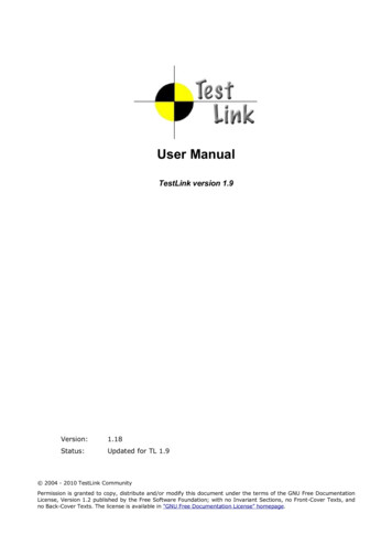
17 of 65Report No.: STS1704135F015.8 FIELD STRENGTH OF SPURIOUS RADIATION MEASUREMENTTest overviewRadiated spurious emissions measurements are performed using the substitution method describedinANSI/TIA-603-D-2010 with the EUT transmitting into an integral antenna. Measurements on signalsoperating below 1GHz are performed using horizontally and vertically polarized tuned dipoleantennas.Measurements on signals operating above 1GHz are performed using vertically and horizontally polarizedhorn antennas. All measurements are performed as peak measurements whilethe EUT isoperating at maximum power and at the appropriate frequencies.It is measured by means of a calibrated spectrum analyzer and scanned from 30 MHz up to afrequency including its 10th harmonic.Test procedure1. The testing FCC KDB 971168 D01 Section 5.8 and ANSI/TIA-603-D-2010-Section 2.2.12.2(b)2. RBW 100kHz for emissions below 1GHz and 1MHz for emissions above 1GHz3. VBW 3 x RBW4. Span 1.5 times the OBW5.No. of sweep points 2 x span/RBW6. Detector Peak7. Trace mode max hold8. The trace was allowed to stabilize9. Effective Isotropic Spurious Radiation was measured by substitution method accordingto TIA/EIA-603-D. The EUT was replaced by the substitution antenna at same location, andthen a known power from S.G. was applied into the dipole antenna through a Tx cable, andthen recorded the maximum Analyzer reading through raised and lowered the test antenna.The correction factor (in dB) S.G. - Tx Cable loss Substitution antenna gain - Analyzerreading. Then the EUT's EIRP/ERP was calculated with the correction factor,ERP/EIRP P.SG GT – LCERP/EIRP effective or equivalent radiated power, respectively (expressed in the same units as PMeas, typically dBW or dBm);P.SG measured transmitter output power or PSD, in dBm or dBW;GT gain of the transmitting antenna, in dBd (ERP) or dBi (EIRP);LC signal attenuation in the connecting cable between the transmitter and antenna, in dB.
18 of 65TEST SETUPFor radiated test from 30MHz to 1GHzFor radiated test from above 1GHzReport No.: STS1704135F01
19 of 65Report No.: STS1704135F01APPENDIX ATESTRESULTA1CONDUCTED OUTPUT POWERGSM 850:ModeGSM850GPRS850EDGE850(1 Slot)Frequency (MHz)AVG ency (MHz)AVG 8.14PCS 1900:ModeGSM1900GPRS1900EDGE1900(1 Slot)
20 of 65Report No.: STS1704135F01UMTS BAND VModeWCDMA 850RMCHSDPASubtest 1HSDPASubtest 2HSDPASubtest 3HSDPASubtest 4HSUPASubtest 1HSUPASubtest 2HSUPASubtest 3HSUPASubtest 4HSUPASubtest 5Frequency(MHz)AVG 19.25
21 of 65Report No.: STS1704135F01UMTS BAND IIModeWCDMA 1900RMCHSDPASubtest 1HSDPASubtest 2HSDPASubtest 3HSDPASubtest 4HSUPASubtest 1HSUPASubtest 2HSUPASubtest 3HSUPASubtest 4HSUPASubtest 5Frequency(MHz)AVG 9.611907.618.47
22 of 65A2 PEAK-TO-AVERAGE RADIOPCS 1900:ModeFrequency (MHz)PCS1900GPRS1900EDGE1900(1 Slot)Report No.: STS1704135F01PEAK PowerAVG .4528.350.101909.828.2628.140.12Frequency (MHz)PEAK PowerAVG .4722.952.521907.624.5121.662.85UMTS BAND II:ModeWCDMA 1900RMCHSDPA 1900HSUPA 1900
23 of 65Report No.: STS1704135F01A3 TRANSMITTER RADIATED POWER (EIRP/ERP)Radiated Power (ERP) for GSM 850 onE.R.P(dBm)PolarizationOf Max. PassS 5.19836.6PMeas
24 of 65Report No.: STS1704135F01Radiated Power (EIRP) for PCS 1900 MHZResultModePCS1900GPRS1900EDGE1900FrequencyS blelossE.I.R.P.(dBm)Of 762.4310.3527.68VerticalPass
25 of 65Report No.: STS1704135F01Radiated Power (ERP) for WCDMA Band VResultModeBand VFrequencyConclusion(dBm)PolarizationOf Pass846.615.780.466.521.82VerticalPassS G.LevelGain(dBi)PMeas diated Power (EIRP) for WCDMA Band IIResultModeBand IIFrequencyS blelossE.I.R.P.(dBm)Of 07.613.72.4310.3521.62VerticalPass
26 of 65Report No.: STS1704135F01A4 OCCUPIED BANDWIDTH(99% OCCUPIED BANDWIDTH/26DB BANDWIDTH)Occupied Bandwidth for GSM 850 bandOccupied BandwidthEmission Bandwidth(99%)( kHz)(-26dBc)( kHz)824.2246.34314.9Middle Channel836.6246.09315.0High Channel848.8250.16322.8ModeFrequency(MHz)Low ChannelOccupied Bandwidth for GPRS 850 bandOccupied BandwidthEmission Bandwidth(99%)( kHz)(-26dBc)( kHz)824.2242.96317.5Middle Channel836.6242.88311.0High Channel848.8248.09317.2ModeFrequency(MHz)Low ChannelOccupied Bandwidth for EGPRS 850 bandOccupied BandwidthEmission Bandwidth(99%)( kHz)(-26dBc)( kHz)824.2246.61323.2Middle Channel836.6246.39319.3High Channel848.8243.41317.0ModeFrequency(MHz)Low Channel
27 of 65Report No.: STS1704135F01Occupied Bandwidth for GSM1900 bandOccupied BandwidthEmission Bandwidth(99%)( kHz)(-26dBc)( kHz)1850.2246.46318.9Middle Channel1880.0245.72317.0High Channel1909.8244.85314.8ModeFrequency(MHz)Low ChannelOccupied Bandwidth for GPRS 1900 bandOccupied BandwidthEmission Bandwidth(99%)( kHz)(-26dBc)( kHz)1850.2245.85316.8Middle Channel1880.0245.30311.6High Channel1909.8244.36318.2ModeFrequency(MHz)Low ChannelOccupied Bandwidth for EDGE 1900 bandOccupied BandwidthEmission Bandwidth(99%)( kHz)(-26dBc)( kHz)1850.2243.25306.6Middle Channel1880.0245.49312.4High Channel1909.8245.38318.1ModeFrequency(MHz)Low ChannelOccupied Bandwidth for UMTS band VOccupied BandwidthEmission Bandwidth(99%)( MHz)(-26dBc)( MHz)826.44.17374.803Middle Channel836.64.29575.511High Channel846.64.23934.855ModeFrequency(MHz)Low ChannelOccupied Bandwidth for UMTS band IIOccupied BandwidthEmission Bandwidth(99%)( MHz)(-26dBc)( MHz)1852.44.28875.172Middle Channel18804.20074.840High Channel1907.64.23644.949ModeFrequency(MHz)Low Channel
28 of 65GSM 850 CH 128GSM 850 CH 190GSM 850 CH 251Report No.: STS1704135F01
29 of 65GPRS 850 CH 128GPRS 850 CH 190GPRS 850 CH 251Report No.: STS1704135F01
30 of 65EDGE 850 CH 128EDGE 850 CH 190EDGE 850 CH 251Report No.: STS1704135F01
31 of 65PCS 1900 CH 512PCS 1900 CH 661PCS 1900 CH 810Report No.: STS1704135F01
32 of 65GPRS 1900 CH 512GPRS 1900 CH 661GPRS 1900 CH 810Report No.: STS1704135F01
33 of 65EDGE 1900 CH 512EDGE 1900 CH 661EDGE 1900 CH 810Report No.: STS1704135F01
34 of 65UMTS BAND V CH 4132UMTS BAND V CH 4183UMTS BAND V CH 4233Report No.: STS1704135F01
35 of 65UMTS BAND II CH 9262UMTS BAND II CH 9400UMTS BAND II CH 9538Report No.: STS1704135F01
36 of 65Report No.: STS1704135F01A5 FREQUENCY STABILITYNormal Voltage 3.7V. ;Battery End Point (BEP) 3.4 V.;Maximum Voltage 4.2 VGSM 850 Middle Channel/836.6MHzTemperature( C)50Freq. Dev.(Hz)Freq. 42-3030.880.03710Voltage(Volt)Normal Voltage25Maximum ASSLimitResult2.5ppmPASSGPRS 850 Middle Channel/836.6MHzTemperature( C)50Freq. Dev.(Hz)Freq. 32-3015.870.01910Voltage(Volt)Normal Voltage25Maximum Voltage27.320.03325BEP22.310.027
37 of 65Report No.: STS1704135F01EDGE 850 Middle Channel/836.6MHzTemperature( C)50403020100-10-20-302525Voltage(Volt)Normal VoltageMaximum VoltageBEPFreq. .5330.1015.67Freq. .0210.0360.019LimitResult2.5ppmPASS
38 of 65Report No.: STS1704135F01GSM 1900 Middle Channel/1880MHzTemperature( C)50Voltage(Volt)Freq. Dev.(Hz)Freq. 1510Normal Voltage-3022.790.01225Maximum SSGPRS 1900 Middle Channel/1880MHzTemperature( C)50Freq. Dev.(Hz)Freq. 14-3014.700.00810Voltage(Volt)Normal Voltage25Maximum Voltage22.040.01225BEP24.430.013
39 of 65Report No.: STS1704135F01EDGE 1900 Middle Channel/1880MHzTemperature( C)50Voltage(Volt)Freq. Dev.(Hz)Freq. 1710Normal Voltage-3020.520.01125Maximum uthorizedBandPASS
40 of 65Report No.: STS1704135F01WCDMA V Middle Channel/836.6MHzTemperature( C)50Voltage(Volt)Freq. Dev.(Hz)Freq. 3910Normal Voltage-3034.210.04125Maximum Voltage35.760.04325BEP34.180.041LimitResult2.5pp
Product Designation: GPS Tracker Hardware version number: 0.2 Software version number: V7 FCC ID: 2AAI6-TRKM010 Tx Frequency: GSM/GPRS/EDGE: 850: 824.2 MHz 848.8 MHz 1900: 1850.2 MHz 1909.8MHz WCDMA: Band V: 826.4 MHz 846.6 MHz Band II: 1852.4 MHz 1907.6 MHz