Transcription
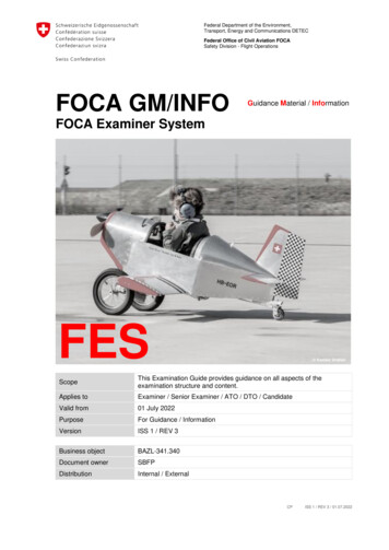
Journal of KONES Powertrain and Transport, Vol. 23, No. 3 2016ISSN: 1231-4005e-ISSN: 2354-0133DOI: 10.5604/12314005.1216400AVIATION PISTON ENGINES – FLIGHT PARAMETER ANALYSISPawel Boguszewicz, Pawel GlowackiInstitute of AviationDepartment of Space TechnologiesKrakowska Avenue 110/114, 02-256 Warsaw, Polandtel.: 48 228460011, ext. 618e-mail: pawel.boguszewicz@ilot.edu.pl, pawel.glowacki@ilot.edu.plAbstractA program and tools enabling general aviation operators in our country the exploitation of the piston engines oncondition has been developed in the Institute of Aviation. Apart from the existing and strictly supervised enginemanuals tasks, the program introduces, among other things, new maintenance mandatory activities like engineparameter monitoring during cruise and climb and a way of assignation diagnostic tolerance limits for them. That hasnever been performed in the aviation piston engines maintenance practice.In order to improve such analysis a flight data recorder (FDR) EDM 900 has been installed on the DA20- C1„Katana” aircraft equipped with IO-240-B engine, which will allow elimination of the pilot's read errors andexamination of the changes in the parameters during the entire flight. This will enable estimating if at a certain time ofthe flight a specified engine parameter is not exceeding the permissible values. Parameters from cruise have to berecorded in the similar range of the engine rpm’s. The parameters are oil pressure, oil temperature, cylinder headtemperature, EGT, fuel flow, outside air temperature, rpm and altitude. Lower and upper acceptable limit valuesshould be set, in which they can be contained throughout engine life. Engineers should also observe the trend of theirchanges.This article shows results of the aviation piston engine parameters analysis taken from FDR for ground runs,take-offs and cruise flight phases.Keywords: aviation piston engine, on-condition maintenance, engine flight parameter1. IntroductionA reliable aircraft engine guarantees safe realization of a flight. It concerns particularlyairplanes powered by a single engine where each failure can cause a serious event. At present,there are more than 1,000 piston engines in exploitation in Poland, most of them (90%) powersingle engine aircraft [8].Almost 50% of aviation occurrences contained in [7] and caused by power plants installed onthose aircraft can be assigned to the piston engine itself. Most of the events are connected withpowertrain and cylinder systems. There were events caused by cracked exhaust valves. In addition,carbon deposit on valves has been observed. Some occurrences were caused by different failuresof the cylinders. It can be presumed that those damages were due to engines overheating, resultingfrom improper exploitation. Fig. 1 shows the number of the aviation events caused by pistonengines in the years 2012-2015.Improperly installed/connected oil pipes causing leaks are the main but not the only reason forthe reported events connected with the engine oil system. They occurred due to maintenanceimperfections. Oil system faults have a significant impact on flight safety. It needs to bementioned that in 23 cases of the oil system malfunctions in the years 2008-2015, 16 of themresulted in aborted flights or emergency landings [7]. Fig. 2 shows the number of the aviationevents caused by the piston engines oil system in the years 2012-2015.The above descriptions presented lead to the formulation of the thesis that aircraft pistonengines require changes in the current exploitation system in order to improve flight safety.
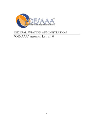
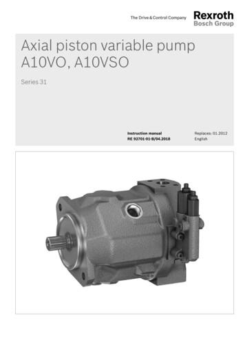
P. Boguszewicz, P. GlowackiIn addition to the existing maintenance and operational requirements, such a system should includenew tasks like engine flight parameter monitoring which is an important part of the engine oncondition ig.1. Number of the piston engines failures caused aviation events655432322102012201320142015Fig. 2. Number of the piston engines oil system failures caused aviation events2. Research methodThe concept of the aviation piston engines on-condition exploitation established in the Instituteof Aviation was presented in the article [1]. At that time, engine parameters were registered by theaircrew. Installation of the EDM 900 Flight Data Recorder (FDR) on the DA20-C1 aircraftpowered by Continental IO-240-B engine, allowed elimination of the pilot’s read errors andexamination of the parameter changes during the entire flight if at a certain time the parametersdo not exceed the permissible values. Fig. 3 shows instrument panel view of the DA21-C1 aircraftbefore a) and after b) flight data recorder EDM 900 installation.a)b)Fig. 3. Aircraft instrument panel view before a) and after b) flight data recorder EDM 900 installation42
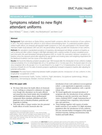
Aviation Piston Engines – Flight Parameter AnalysisThe most important part is the way the engine parameters from the flight are analysed. Theyhave to be recorded during take-off/climb and cruise but in the same range of engine rpm’s. It isimportant to track trends of their changes. The parameters are:1. Oil pressure.2. Oil temperature.3. Cylinder head temperature.4. EGT (Exhaust Gas Temperature).5. Fuel flow.They are registered on the FDR every second.Cruise data from flights, which are taken into consideration for diagnostic purposes areaccepted only when registered after one minute of the flight stabilization, at the same altitude withengine rotation speed in a range between 2100-2200 rpm.Assignation of the engine’s parameters values from take-off/climb are calculated as follows:When the aircraft during take-off reaches a speed of 50 km/h, an average value of each engineparameter registered for 50 seconds from that point is calculated. It means that in our case it is anaverage of 50 measurements.Determination of the range, in which the above parameter values should be contained. It needsto be carried out based on the data from each flight (the first 50 hours after the engine installation)and take-off/climb (the first 20 flights after engine installation), assuming their Gaussiandistribution.For each parameter, the mean value should be counted.and the standard deviation:PŚR 𝑛𝑛𝑖𝑖 1 𝑃𝑃𝑃𝑃 /N,Ϭ 𝟐𝟐 𝒏𝒏𝒊𝒊 𝟏𝟏(𝑷𝑷𝑷𝑷 𝑷𝑷ś𝒓𝒓)𝑵𝑵 𝟏𝟏(1),(2)where:N – number of flights,Pi – parameter value,PŚR – mean value.For the next overhaul, a replacement of the engine or the propeller replacement, each parametervalue should be within established range, from m 3ϭ to m-3ϭ.If any of the parameter values exceeds the limit, the cause of it has to be determinedimmediately.Figure 3 shows as an example a graphical summary of the above-mentioned descriptionsand calculations.Fig. 3. Example of graphical representation of the value changes for one of the operational parameters of the enginein flight. The operational upper limit is greater than the upper diagnostic (m 3ϭ) limit43
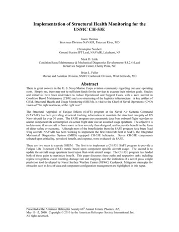
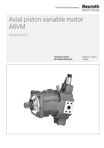
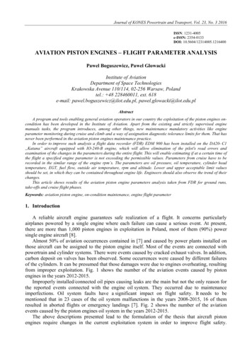
P. Boguszewicz, P. Glowacki3. The calculations resultsFigure 4 shows picture of the engine IO-240-B parameter changes during two flights, recordedon the EDM 900 FDR installed on DA20-C1 aircraft. Upper part of the picture presents eachcylinder head temperature and EGT. Lower part shows engine rpm, fuel flow, oil temperature.Remaining necessary for engine condition assessment parameters: oil pressure, fuel pressure,outside air temperature (OAT), altitude, aircraft speed are not shown on graphs.Fig. 4. Example of two flights registered on EDM 900 flight data recorderFigure 5 shows view from the top of the IO-240-B engine installed on DA20-C1 aircraft.Fig. 5. IO-240-B engine seen from the top, 1 – cylinder no 4, 2 – baffles, 3 – manifold of the air supplied to thecylinders, 4 – air supply hose, 5 – throttleThe installation of the FDR besides the engine’s oil and fuel parameter registration madeit possible for every cylinder’s head temperature as well as for EGT, measured after each exhaustvalve. It is very important because the condition of the aircraft’s baffles could be evaluated moreprecisely. They guide the cooling air around cylinder heads and barrels. In addition, other baffleschannel provides cooling air into oil radiators. If the cylinder head temperature or oil temperatureapproaching the limit than the baffles technical condition has to be checked. When they areproperly installed, troubleshooting in order to find reason high temperatures could be established.44
Aviation Piston Engines – Flight Parameter Analysis3.1. CruiseFigure 6 shows each cylinder head temperature during cruise phase of the flight, recorded onthe EDM 900 FDR. Also, operating as well as calculated new, so-called diagnostic limits arepresented.Fig. 6. Each cylinder head temperature limit during cruise of the IO-240-B engine installed on DA21-C1 aircraftFDR has enabled precise readings of the cylinder’s temperature. It has to be pointed out thatdiagnostic limits calculated for the cylinders 3 and 4 are significantly lower than for the cylinders1 and 2. Such situation results from better cooling of the cylinders 3 and 4, which are closer to theengine’s air inlet.Figure 7 presents established diagnostic limit for engine oil temperature, while Fig. 8 showsengine’s rpm values when its parameters were recorded.Fig. 7. Engine oil temperatures during cruise and calculated diagnostic limit45
P. Boguszewicz, P. GlowackiFig. 8. Engine rpm’s values during cruise when its parameters were recordedAll of the engine’s new calculated diagnostic limits for its parameters are below operationalrestrictions included in the IO-240-B Engine Manual [5] for the cruise phase of the aircraft flight.3.2. Take-off/ClimbThe phase of the flight during which aircraft engine is subject to high temperature stressesis take-off/climb. Recorded from this part of the aircraft flight engine parameters are providingimportant diagnostic information, describing an engine condition. Knowledge of their values in thediscussed here flight phase allows an engineer (computer program) to perform calculations andas a result for take-off/climb parameters, diagnostic limits establishment. Such procedure is onlypossible if engine’s parameters are registered automatically. Fig. 9 shows each cylinder headtemperature during take-off/climb, recorded on the EDM 900 FDR. Also operating as well ascalculated new, diagnostic limits are presented.Fig. 9. Each cylinder head temperature limit during take-off/climb of the IO-240-B engine installed on DA20-C1aircraft46
Aviation Piston Engines – Flight Parameter AnalysisFigure 10 presents engine oil temperature parameters during take-off/climb phase of the flightand calculated diagnostic as well as engine manual operational limit.Fig. 10. Engine oil temperatures during take-off/climb and calculated diagnostic limitLower diagnostic limit especially for cylinder head and for engine oil temperatures are muchhigher than engine manual minimum limit. For engine TBO (Time Between Overhaul) extension,it is advisable to perform engine heating before flight to higher temperature values than thosegiven in the manual.4. ConclusionsPresented in the article measurement results are taken from only first FDR installed on theaircraft with engine “on-watch”. This enabled assessment of diagnostic limits for that engine.Further continuing measurements will enable engine’s parameter changes within its life.Positive outcomes of the results for the engine analysis based on the Flight Data Recorder willenable the extension of FDR capabilities for the aircraft flight parameters, which will lead tothe introduction of an objective flight control and thus will improve flight safety. A registeredengine as well as flight management parameters analysis will make possible accurate detectionof the failure causes. Also, immediate information about any parameter exceedance overdiagnostic or aircraft/engine manual limits will be provided.For every single engine, individual diagnostic limits have to be established.5. Plan for the futureEngines vibration is an important parameter indicating possible imbalance of the variouspowertrain elements as well as irregular combustion processes. Up to now, vibration monitoringsystem has not been adopted on aviation piston engines. There are scheduled engine tests on thenewly opened in the Institute of Aviation test-cell in order to find the best place on the engine forvibration sensor/s installation. Promising results of such research will allow installationof the vibration monitoring system on the exploited engine.AcknowledgementThe work is financed from the Institute of Aviation statutory fund (Project no 21751).References[1] Głowacki, P., Łukasik, B., Aviation piston engines on – condition maintenance – proposal,Combustion Engines, PTNSS, No. 3 (162), pp. 52-63, 2015.[2] Lewitowicz, J., Żyluk, A., Podstawy eksploatacji statków powietrznych, Tom V, Technicznaeksploatacja statków powietrznych, ITWL, Warszawa 2009.47
P. Boguszewicz, P. Glowacki[3] Szczeciński, S., Lotnicze silniki tłokowe, Wydawnictwo MON, Warszawa 1969.[4] Wiśniewski, S., Obciążenia cieplne silników tłokowych, Wydawnictwo Komunikacjii Łączności, Warszawa 1972.[5] IO-240-AB maintenance and overhaul manual, Publication M-6, Continental Motors, 2011.[6] Tips on Engine Care, Continental Motors, Inc., TEC, 2011.[7] Database ECCAIRS (European Coordination Centre for Aviation Incident ReportingSystems).[8] nalizy.48
This article shows results of the aviation piston engine parameters analysis taken from FDR for ground runs, take-offs and cruise flight phases. Keywords: aviation piston engine, on-condition maintenance, engine flight parameter. 1. Introduction. A reliable aircraft engineguarantees safe realization of flight. It concerns particularlya