Transcription
instruction manualNetLinx IntegratedControllers(NI-2000, NI-3000, and NI-4000)N e t L i n x C e n t ra l C o n t r o l l e r s a n d C a r d sMore user manuals on ManualsBase.com
AMX Limited Warranty and DisclaimerAMX Corporation warrants its products to be free of defects in material and workmanship under normal use for three(3) years from the date of purchase from AMX Corporation, with the following exceptions: Electroluminescent and LCD Control Panels are warranted for three (3) years, except for the display and touchoverlay components that are warranted for a period of one (1) year. Disk drive mechanisms, pan/tilt heads, power supplies, and MX Series products are warranted for a period of one(1) year. AMX Lighting products are guaranteed to switch on and off any load that is properly connected to our lightingproducts, as long as the AMX Lighting products are under warranty. AMX Corporation does guarantee thecontrol of dimmable loads that are properly connected to our lighting products. The dimming performance orquality cannot be guaranteed due to the random combinations of dimmers, lamps and ballasts or transformers. Unless otherwise specified, OEM and custom products are warranted for a period of one (1) year. AMX Software is warranted for a period of ninety (90) days. Batteries and incandescent lamps are not covered under the warranty.This warranty extends only to products purchased directly from AMX Corporation or an Authorized AMX Dealer.All products returned to AMX require a Return Material Authorization (RMA) number. The RMA number isobtained from the AMX RMA Department. The RMA number must be clearly marked on the outside of each box.The RMA is valid for a 30-day period. After the 30-day period the RMA will be cancelled. Any shipments receivednot consistent with the RMA, or after the RMA is cancelled, will be refused. AMX is not responsible for productsreturned without a valid RMA number.AMX Corporation is not liable for any damages caused by its products or for the failure of its products to perform.This includes any lost profits, lost savings, incidental damages, or consequential damages. AMX Corporation is notliable for any claim made by a third party or by an AMX Dealer for a third party.This limitation of liability applies whether damages are sought, or a claim is made, under this warranty or as a tortclaim (including negligence and strict product liability), a contract claim, or any other claim. This limitation ofliability cannot be waived or amended by any person. This limitation of liability will be effective even if AMX Corporation or an authorized representative of AMX Corporation has been advised of the possibility of any such damages.This limitation of liability, however, will not apply to claims for personal injury.Some states do not allow a limitation of how long an implied warranty last. Some states do not allow the limitation orexclusion of incidental or consequential damages for consumer products. In such states, the limitation or exclusion ofthe Limited Warranty may not apply. This Limited Warranty gives the owner specific legal rights. The owner mayalso have other rights that vary from state to state. The owner is advised to consult applicable state laws for fulldetermination of rights.EXCEPT AS EXPRESSLY SET FORTH IN THIS WARRANTY, AMX CORPORATION MAKES NOOTHER WARRANTIES, EXPRESSED OR IMPLIED, INCLUDING ANY IMPLIED WARRANTIES OFMERCHANTABILITY OR FITNESS FOR A PARTICULAR PURPOSE. AMX CORPORATIONEXPRESSLY DISCLAIMS ALL WARRANTIES NOT STATED IN THIS LIMITED WARRANTY. ANYIMPLIED WARRANTIES THAT MAY BE IMPOSED BY LAW ARE LIMITED TO THE TERMS OF THISLIMITED WARRANTY.This product includes the GoAhead Web Server.Copyright (c) 2003 GoAhead Software, Inc. All Rights Reserved.This product includes software developed by the OpenSSL Project for use in the OpenSSL Toolkit.(http://www.openssl.org/)This product includes cryptographic software written by Eric Young (eay@cryptsoft.com)More user manuals on ManualsBase.com
Table of ContentsTable of ContentsIntroduction .1NI-2000 Specifications . 1NI-3000 Specifications . 5NI-4000 Specifications . 10Quick Setup and Configuration Overview .15Installation Procedures. 15Configuration and Communication . 15Update the Controller and Control Card Firmware. 16Program NetLinx Security into the On-Board Master . 16Connections and Wiring .17Setting the Configuration DIP Switch (for the Program Port) . 17Baud rate settings . 17Program Run Disable (PRD) mode. 17Using the Configuration DIP switch. 18Modes and Front Panel LED Blink Patterns. 18Wiring Guidelines . 18Preparing captive wires. 19Wiring length guidelines . 19Wiring a power connection. 19Using the 4-pin mini-Phoenix connector for data and power . 20Using the 4-pin mini-Phoenix connector for data with external power . 20Program Port Connections and Wiring. 21RS-232/422/485 Device Port Wiring Specifications . 21ICSNet RJ-45 Connections/Wiring . 22ICSHub OUT port. 23Ethernet 10/100 Base-T RJ-45 Connections/Wiring . 23Ethernet ports used by the Integrated Controllers . 24Relay Connections and Wiring . 24Relay connections. 25Input/Output (I/O) Connections and Wiring . 25IR/Serial Connections and Wiring . 26NetLinx Control Card Slot Connector (NI-4000 unit only) . 27NetLinx Integrated ControllersMore user manuals on ManualsBase.comi
Table of ContentsInstallation and Upgrading . 29Installing NetLinx Control Cards (NI-4000 Only) . 29Setting the NetLinx Control Card Addresses (NI-4000 Only). 30Device:Port:System (D:P:S). 30Removing NetLinx Control Cards (NI-4000 Only) . 31Compact Flash Upgrades . 31Accessing the internal components on an Integrated Controller. 31Installation of Compact Flash upgrades. 32Closing and Securing the Integrated Controller . 33Installing the Integrated Controller into an Equipment Rack . 34Configuration and Firmware Update . 37Communicating with the Master via the Program Port. 37Setting the System Value. 38Using multiple NetLinx Masters. 39Changing the Device Address on a NetLinx Device . 40Recommended NetLinx Device numbers. 41Resetting the Factory Default System and Device Values. 41Obtaining the Master’s IP Address (using DHCP) . 42Assigning a Static IP to the NetLinx Master . 43Communicating with the On-board Master via an IP. 44Verifying the current version of NetLinx Master Firmware . 46Upgrading the On-board Master Firmware via an IP . 46Upgrading the NI Controller Firmware via an IP . 48Upgrading the new NI Controller firmware via an IP . 49Upgrading the Control Card Firmware via an IP . 51NetLinx Security and Web Server . 53NetLinx Security web browser and feature support . 53New Master Firmware Security Features. 54NetLinx Security Terms. 54Accessing the NetLinx Master via its IP Address. 55WebControl Tab . 55Default Security Configuration . 56Security Tab . 57Security tab - Enable Security page. 58Security tab - Add Group page. 59Security tab - Modify Group page . 60Security tab - Group Directory Associations page . 61Security tab - Add User page . 63iiMore user manuals on ManualsBase.comNetLinx Integrated Controllers
Table of ContentsSecurity tab - Modify User page. 64Security tab - User Directory Associations page. 65Security tab - SSL Server Certificate page . 67Security tab - Export Certificate Request page . 69Security tab - Import Certificate page. 69System Tab . 70Show Devices Tab . 70Network Tab . 70Master Security Setup Procedures. 71Setting the system security options for a NetLinx Master (Security Options Menu) . 71Adding a Group and assigning their access rights. 72Modifying an existing Group’s access rights . 73Showing a list of authorized Groups . 74Deleting an existing Group. 74Adding a Group directory association . 75Confirming the new directory association . 76Deleting a directory association . 76Adding a User and configuring their access rights. 77Modifying an existing User’s access rights . 78Showing a list of authorized Users. 79Deleting a User . 79Adding a User directory association. 80Confirming the new directory association . 81Deleting a directory association . 81SSL Certificate Procedures . 81Self-Generating a SSL Server Certificate Request . 82Creating a Request for a SSL Server Certificate . 83Importing a CA certificate to the Master over a secure SSL connection. 84Display SSL Server Certificate Information. 85Regenerating an SSL Server Certificate Request. 85Common Steps for Requesting a Certificate from a CA. 86Accessing an SSL-Enabled Master via an IP Address. 88Using your NetLinx Master to control the G4 panel . 90Using your NetLinx Master to control the G3 panel . 91What to do when a Certificate Expires . 92NetLinx Security with a Terminal Connection .93NetLinx Security Features . 93Initial Setup via a Terminal Connection. 93Establishing a Terminal connection . 93NetLinx Integrated ControllersMore user manuals on ManualsBase.comiii
Table of ContentsAccessing the Security configuration options. 94Option 1 - Set system security options for NetLinx Master (Security Options Menu) . 95Option 2 - Display system security options for NetLinx Master. 96Option 3 - Add user . 96Option 4 - Edit User. 97Option 5 - Delete user . 99Option 6 - Show the list of authorized users . 99Option 7 - Add Group . 99Option 8 - Edit Group . 102Option 9 - Delete Group . 102Option 10 - Show List of Authorized Groups. 103Option 11 - Set Telnet Timeout in seconds. 103Option 12 - Display Telnet Timeout in seconds . 103Option 13 - Make changes permanent by saving to flash . 103Main Security Menu . 104Default Security Configuration . 105Help menu. 106Logging Into a Session. 107Logout . 108Help Security. 108Setup Security. 108Programming . 109Converting Axcess Code to NetLinx Code. 109Using the ID Button . 109Device:Port:System (D:P:S). 109Program Port Commands . 110ESC Pass Codes . 113Notes on Specific Telnet/Terminal Clients . 113WindowsTM client programs. 113Linux Telnet client . 114LED Disable/Enable Send Commands . 114RS-232/422/485 Send Commands . 114RS-232/422/485 Send String Escape Sequences . 117IR / Serial Ports Channels. 118IR RX Port Channels. 118IR/Serial Send Commands. 118Input/Output Send Commands. 123Troubleshooting . 125ivMore user manuals on ManualsBase.comNetLinx Integrated Controllers
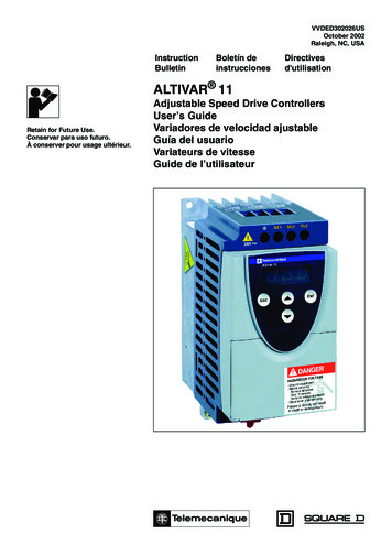
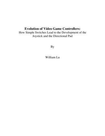
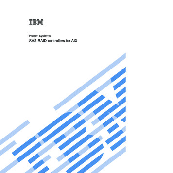
IntroductionIntroductionNetLinx Integrated Master Controllers can be programmed to control RS-232/422/485, Relay, IR/Serial, and Input/Output devices through the use of both the NetLinx programming language andthe NetLinx Studio application (version 2.2 or higher). Another key feature of this products is theability to easily access the configuration switches without having to remove acover plate.NetLinx Integrated Master Controller FeaturesNI-2000(FG2105-01) 1 RS-232 Program port 3 RS-232/RS-422/RS-485 ports 4 IR/Serial Output ports 4 Digital Input/Output ports 4 RelaysNI-3000(FG2105-02) 1 RS-232 Program port 7 RS-232/RS-422/RS-485 ports 8 IR/Serial Output ports 8 Digital Input/Output ports 8 RelaysNI-4000(FG2105) Support for up to 4 NetLinx control cards (such as NXC-COM2, NXC-IRS4, etc.) 1 RS-232 Program port 7 RS-232/RS-422/RS-485 ports 8 IR/Serial Output ports 8 Digital Input/Output ports 8 RelaysThe NI series of controllers use a combination lithium battery and clock crystal package called aTimekeeper. Only one Timekeeper unit is installed within a given NI controller. The battery can beexpected to have up to 3 years of usable life under very adverse conditions. Actual life isappreciably longer under normal operating conditions. This calculation is based on storing the unitwithout power in 50 C (120 F) temperature until battery levels are no longer acceptable. The partnumber for a replacement battery is 57-0032.NI-2000 SpecificationsThe front panel LEDs (FIG. 1) are grouped by control type and are numbered according to theircorresponding port (connector) numbers on the rear of the unit. The back of the unit containsthree RS-232/422/485, one Relay, one IR/Serial and one I/O connectors. In addition, this unitprovides an ID pushbutton, AXlink LED, and other related connectors. FIG. 2 shows the front andrear of the NI-2000.NetLinx Integrated ControllersMore user manuals on ManualsBase.com1
IntroductionFIG. 1 NI-2000 NetLinx Integrated Controller (front view)RS-232/422/485 TX/RX LEDs (red/yellow)Link/Active-Status-Output-InputRelay LEDs (red)IR/Serial LEDs (red)I/O LEDs(yellow)FrontICSNet (2)RearRS-232/422/485 (Ports 1-3)Relays(Port 4)ICSHub OutEthernetIR/Serial (Ports 5-8)I/O (Port 9)DIPswitchProgramportAXLink LED(green)AXLinkportPWRID PushbuttonFIG. 2 NI-2000 front and rear panel componentsNI-2000 SpecificationsDimensions (HWD): 3.47" x 17.00" x 3.47" (8.81 cm x 43.18 cm x 8.82 cm) 2 RU (rack unit) highPower requirements: 700 mA @ 12 VDCMemory: 32 MB SDRAM 1 MB of Non-volatile FlashCompact Flash: 32 MB Card (upgradeable). Refer to the Optional Accessories section onpage 5 for more information.Weight: 4.50 lbs (2.04 kg)Enclosure: Metal with black matte finish2More user manuals on ManualsBase.comNetLinx Integrated Controllers
IntroductionNI-2000 Specifications (Cont.)Front Panel Components:LINK/ACT Green LED lights when the Ethernet cable is connected and an active linkis established. This LED also blinks when receiving Ethernet data packets.Status Green LED lights to indicate that the system is programmed andcommunicating properly.Output Red LED lights when the Controller transmits data, sets channels On/Off,sends data strings, etc.Input Yellow LED blinks when the Controller receives data from button pushes,strings, commands, channel levels, etc.RS-232/422/485 LEDs Three sets of red and yellow LEDs light to indicate the rear DB9 Ports 1-3are transmitting or receiving RS-232, 422, or 485 data:- TX LEDs (red) light when transmitting data- RX LEDs (yellow) light when receiving data- LED activity reflects transmission and reception activityRelay LEDs Four red LEDs light to indicate the rear relay channels 1-4 are active(closed). These LEDs reflect the state of the relay on Port 4 If the relay is engaged LED On and if the relay is Off LED OffIR/Serial LEDs Four red LEDs light to indicate the rear IR/Serial channels 1-4 aretransmitting control data on Ports 5-8 LED indictor for each IR port remains lit for the length of time that IR/Serialdata is being generatedI/O LEDs Four yellow LEDs light when the rear I/O channels 1-4 are active LED indicator for each I/O port reflects the state of that particular portRack-mount brackets Provide an installation option for the Integrated Controller to be mountedinto an equipment rack.Rear Panel Components:RS-232/422/485 (Ports 1 -3) Three RS-232/422/485 control ports using DB9 (male) connectors withXON/XOFF (transmit On/transmit Off), CTS/RTS (clear to send/ready tosend), and 300-115,200 baud. Channel range 1-255 Channels 1-254 provide feedback Channel 255 (CTS Push channel): Reflects the state of the CTS Input if a'CTSPSH' command was sent to the port Output data format for each port is selected via software Three DB9 connectors provide RS-232/422/485 terminationICSNet Two RJ-45 connectors for ICSNet interfaceICSHub Out Single RJ-45 connector provides data to another Hub connected to theControllerRelay (Port 4) Four-channel single-pole single-throw relay ports Each relay is independently controlled. Supports up to 4 independent external relay devices Channel range 1-4 Each relay can switch up to 24 VDC or 28 VAC @ 1 A One 8-pin 3.5 mm mini-Phoenix (female) connector provides relayterminationNetLinx Integrated ControllersMore user manuals on ManualsBase.com3
IntroductionNI-2000 Specifications (Cont.)Digital I/O (Port 9) Four-channel binary I/O port for contact closure Each input is capable of voltage sensing. Input format is softwareselectable. Interactive power sensing for IR ports Channel range 1-4 All inputs are assigned to respective IR/Serial ports for "automatic" powercontrol through the use of software commands. Power control is providedvia commands such as: ’PON’, ’POF’, ’POD’, ’DELAY’, I/O Link etc.). Contact closure between GND and an I/O port is detected as a PUSH When used as voltage input - I/O port detects a low signal (0- 1.5 VDC) asa PUSH and a high signal (3.5 - 5 VDC) as a RELEASE When used as an output - each I/O port acts as a switch to GND and israted at 200 mA @ 12 VDC One 6-pin 3.5 mm mini-Phoenix (female) connector provides I/O portterminationIR/Serial (Ports 5-8) Four IR/Serial control ports support high-frequency carriers up to1.142 MHz Each output is capable of two electrical formats: IR or Serial Four IR/Serial data signals can be generated simultaneously. Channel range 1-32,767 Channels 1-128 (output): IR commands Channels 129-253: used as reference channels Channel 254 (feedback): Power Fail (used with 'PON' and 'POF'commands) Channel 255 (feedback): Power status (when IO Link is set) One 8-pin 3.5 mm mini-Phoenix (female) connector provides IR/Serial portterminationIR/Serial (Ports 5-8) Four IR/Serial control ports support high-frequency carriers up to 1.142MHz Each output is capable of two electrical formats: IR or Serial Four IR/Serial data signals can be generated simultaneously Channel range 1-32,767 Channels 1-128 (output): IR commands Channels 129-253: used as reference channels Channel 254 (feedback): Power Fail (used with 'PON' and 'POF'commands) Channel 255 (feedback): Power status (when IO Link is set) One 8-pin 3.5 mm mini-Phoenix (female) connector provides IR/Serial portterminationProgram port Single RS-232 DB9 connector (male) can be connected to a DB9 port on acomputer; used with serial commands, NetLinx programming commands,other DB9 capable devices, and to upload/download information from theNetLinx Studio 2.2 program.Configuration DIP switch Use this DIP switch to set the communication parameters for the rearRS232 Program port.ID pushbutton Sets the NetLinx ID (D) assignment for the device. The D notation is used to explicitly represent a device number.Ethernet port4More user manuals on ManualsBase.com Single RJ-45 port for 10/100 Mbps communication. The Ethernet Portautomatically negotiates the connection speed (10 Mbps or 100 Mbps) andwhether to use half duplex or full duplex mode.NetLinx Integrated Controllers
IntroductionNI-2000 Specifications
AMX Corporation warrants its products to be free of defects in material and workmanship under normal use for three (3) years from the date of purchase from AMX Corporation, with the following exceptions: Electroluminescent and LCD Control Panels are warranted for three (3) years, except for the display and touch