Transcription
G & M CodeREFERENCE MANUALSpecializing in CNC Automation and Motion Control
G and M-code Reference10. Mach 2 G- and M-code language referenceThis section defines the language (G-codes etc.) that are understood andinterpreted by Mach3.Certain functionality which was defined for machines in the NIST NMC(Next Generation Controller) architecture but is not presently implementedmy Mach3 is given in grey type in this chapter. If this functionality isimportant for your application then please let ArtSoft Corporation know yourneeds and they will be included in our development planning cycle.10.1Some definitions10.1.1Linear AxesThe X, Y, and Z axes form a standard right-handed coordinate system of orthogonal linearaxes. Positions of the three linear motion mechanisms are expressed using coordinates onthese axes.10.1.2Rotational AxesThe rotational axes are measured in degrees as wrapped linear axes in which the directionof positive rotation is counterclockwise when viewed from the positive end of thecorresponding X, Y, or Z-axis. By "wrapped linear axis," we mean one on which theangular position increases without limit (goes towards plus infinity) as the axis turnscounterclockwise and decreases without limit (goes towards minus infinity) as the axis turnsclockwise. Wrapped linear axes are used regardless of whether or not there is a mechanicallimit on rotation.Clockwise or counterclockwise is from the point of view of the workpiece. If the workpieceis fastened to a turntable which turns on a rotational axis, a counterclockwise turn from thepoint of view of the workpiece is accomplished by turning the turntable in a direction that(for most common machine configurations) looks clockwise from the point of view ofsomeone standing next to the machine.10.1.3Scaling inputIt is possible to set up scaling factors for each axis. These will be applied to the values of X,Y, Z, A, B, C, I, J and R words whenever these are entered. This allows the size of featuresmachined to be altered and mirror images to be created - by use of negative scale factors.The scaling is the first thing done with the values and things like feed rate are always basedon the scaled values.The offsets stored in tool and fixture tables are not scaled before use. Scaling may, ofcourse, have been applied at the time the values were entered (say using G10).10.1.4Controlled PointThe controlled point is the point whose position and rate of motion are controlled. When thetool length offset is zero (the default value), this is a point on the spindle axis (often calledthe gauge point) that is some fixed distance beyond the end of the spindle, usually near theend of a tool holder that fits into the spindle. The location of the controlled point can bemoved out along the spindle axis by specifying some positive amount for the tool lengthoffset. This amount is normally the length of the cutting tool in use, so that the controlledpoint is at the end of the cutting tool.Using Mach3Mill10-4Rev 1.84-A2
G and M-code reference10.1.5Co-ordinated Linear MotionTo drive a tool along a specified path, a machining system must often co-ordinate themotion of several axes. We use the term "co-ordinated linear motion" to describe thesituation in which, nominally, each axis moves at constant speed and all axes move fromtheir starting positions to their end positions at the same time. If only the X, Y, and Z axes(or any one or two of them) move, this produces motion in a straight line, hence the word"linear" in the term. In actual motions, it is often not possible to maintain constant speedbecause acceleration or deceleration is required at the beginning and/or end of the motion. Itis feasible, however, to control the axes so that, at all times, each axis has completed thesame fraction of its required motion as the other axes. This moves the tool along the samepath, and we also call this kind of motion co-ordinated linear motion.Co-ordinated linear motion can be performed either at the prevailing feed rate, or at rapidtraverse rate. If physical limits on axis speed make the desired rate unobtainable, all axesare slowed to maintain the desired path.10.1.6Feed RateThe rate at which the controlled point or the axes move is nominally a steady rate whichmay be set by the user. In the Interpreter, the interpretation of the feed rate is as followsunless inverse time feed rate (G93) mode is being used: For motion involving one or more of the linear axes (X, Y, Z and optionally A, B,C), without simultaneous rotational axis motion, the feed rate means length units perminute along the programmed linear XYZ(ABC) path For motion involving one or more of the linear axes (X, Y, Z and optionally A, B,C), with simultaneous rotational axis motion, the feed rate means length units perminute along the programmed linear XYZ(ABC) path combined with the angularvelocity of the rotary axes multiplied by the appropriate axis Correction Diametermultiplied by pi (π 3.14152.); i.e. the declared "circumference" of the part For motion of one rotational axis with X, Y, and Z axes not moving, the feed ratemeans degrees per minute rotation of the rotational axis. For motion of two or three rotational axes with X, Y, and Z axes not moving, therate is applied as follows. Let dA, dB, and dC be the angles in degrees through whichthe A, B, and C axes, respectively, must move. Let D sqrt (dA2 dB2 dC2).Conceptually, D is a measure of total angular motion, using the usual Euclidean metric.Let T be the amount of time required to move through D degrees at the current feed ratein degrees per minute. The rotational axes should be moved in co-ordinated linearmotion so that the elapsed time from the start to the end of the motion is T plus anytime required for acceleration or deceleration.10.1.7Arc MotionAny pair of the linear axes (XY, YZ, XZ) can be controlled to move in a circular arc in theplane of that pair of axes. While this is occurring, the third linear axis and the rotationalaxes can be controlled to move simultaneously at effectively a constant rate. As in coordinated linear motion, the motions can be co-ordinated so that acceleration anddeceleration do not affect the path.If the rotational axes do not move, but the third linear axis does move, the trajectory of thecontrolled point is a helix.The feed rate during arc motion is as described in Feed Rate above. In the case of helicalmotion, the rate is applied along the helix. Beware as other interpretations are used on othersystems.10.1.8CoolantFlood coolant and mist coolant may each be turned on independently. They are turned offtogether.Rev 1.84-A210-5Using Mach3Mill
G and M-code Reference10.1.9DwellA machining system may be commanded to dwell (i.e., keep all axes unmoving) for aspecific amount of time. The most common use of dwell is to break and clear chips or for aspindle to get up to speed. The units in which you specify Dwell are either seconds orMilliseconds depending on the setting on Configure Logic10.1.10 UnitsUnits used for distances along the X, Y, and Z axes may be measured in millimetres orinches. Units for all other quantities involved in machine control cannot be changed.Different quantities use different specific units. Spindle speed is measured in revolutionsper minute. The positions of rotational axes are measured in degrees. Feed rates areexpressed in current length units per minute or in degrees per minute, as described above.Warning: We advise you to check very carefully the system's response to changing unitswhile tool and fixture offsets are loaded into the tables, while these offsets are active and/orwhile a part program is excecuting10.1.11 Current PositionThe controlled point is always at some location called the "current position" and Mach3always knows where that is. The numbers representing the current position are adjusted inthe absence of any axis motion if any of several events take place: Length units are changed (but see Warning above) Tool length offset is changed Coordinate system offsets are changed.10.1.12 Selected PlaneThere is always a "selected plane", which must be the XY-plane, the YZ-plane, or the XZplane of the machining system. The Z-axis is, of course, perpendicular to the XY-plane, theX-axis to the YZ-plane, and the Y-axis to the XZ-plane.10.1.13 Tool TableZero or one tool is assigned to each slot in the tool table.10.1.14 Tool ChangeMach3 allows you to implement a procedure for implementing automatic tool changesusing macros or to change the tools by hand when required.10.1.15 Pallet ShuttleMach3 allows you to implement a procedure for implementing pallet shuttle using macros.10.1.16 Path Control ModesThe machining system may be put into any one of two path control modes: (1) exact stopmode, (2) constant velocity mode. In exact stop mode, the machine stops briefly at the endof each programmed move. In constant velocity mode, sharp corners of the path may berounded slightly so that the feed rate may be kept up. These modes are to allow the user tocontrol the compromise involved in turning corners because a real machine has a finiteacceleration due to the inertia of its mechanism.Exact stop does what it says. The machine will come to rest at each change of direction andthe tool will therefore precisely follow the commanded path.Constant velocity will overlap acceleration in the new direction with deceleration in thecurrent one in order to keep the commanded feedrate. This implies a rounding of any cornerbut faster and smoother cutting. This is particularly important in routing and plasma cutting.Using Mach3Mill10-6Rev 1.84-A2
G and M-code referenceThe lower the acceleration of the machine axes, the greater will be the radius of the roundedcorner.In Plasma mode (set on Configure Logic dialog) the system attempts to optimise cornermotion for plasma cutting by a proprietary algorithm.It is also possible to define an limiting angle so that changes in direction of more than thisangle will always be treated as Exact Stop even though Constant Velocity is selected. Thisallows gentle corners to be smoother but avoids excessive rounding of sharp corners evenon machines with low acceleration on one or more axes. This feature is enabled in theConfigure Logic dialog and the limiting angle is set by a DRO. This setting will probablyneed to be chosen experimentally depending on the characteristics of the machine tool and,perhaps, the toolpath of an individual job.10.2Interpreter Interaction with controls10.2.1Feed and Speed Override controlsMach3 commands which enable (M48) or disable (M49) the feed and speed overrideswitches. It is useful to be able to override these switches for some machining operations.The idea is that optimal settings have been included in the program, and the operator shouldnot change them.10.2.2Block Delete controlIf the block delete control is ON, lines of code which start with a slash (the block deletecharacter) are not executed. If the switch is off, such lines are executed.10.2.3Optional Program Stop controlThe optional program stop control (see Configure Logic) works as follows. If this controlis ON and an input line contains an M1 code, program execution is stopped at the end onthe commands on that line until the Cycle Start button is pushed.10.3Tool FileMach3 maintains a tool file for each of the 254 tools which can be used.Each data line of the file contains the data for one tool. This allows the definition of the toollength (Z axis), tool diameter (for milling) and tool tip radius (for turning)10.4The language of part programs10.4.1OverviewThe language is based on lines of code. Each line (also called a "block") may includecommands to the machining system to do several different things. Lines of code may becollected in a file to make a program.A typical line of code consists of an optional line number at the beginning followed by oneor more "words." A word consists of a letter followed by a number (or something thatevaluates to a number). A word may either give a command or provide an argument to acommand. For example, G1 X3 is a valid line of code with two words. "G1" is a commandmeaning "move in a straight line at the programmed feed rate," and "X3" provides anargument value (the value of X should be 3 at the end of the move). Most commands startwith either G or M (for General and Miscellaneous). The words for these commands arecalled "G codes" and "M codes."The language has two commands (M2 or M30), either of which ends a program. A programmay end before the end of a file. Lines of a file that occur after the end of a program are notto be executed in the normal flow so will generally be parts of subroutines.Rev 1.84-A210-7Using Mach3Mill
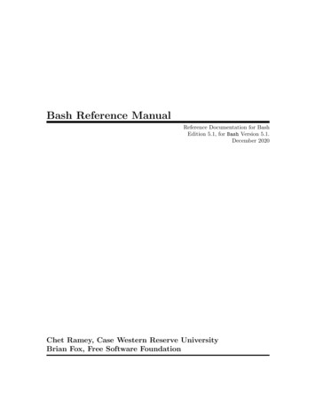
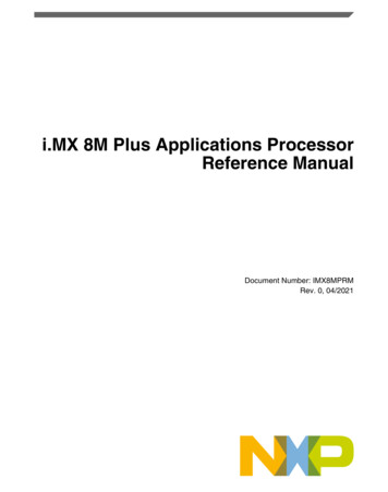
G and M-code 4152425243524452455246MeaningG28 home XG28 home YG28 home ZG28 home AG28 home BG28 home CG30 home XG30 home YG30 home ZG30 home AG30 home BG30 home CScale XScale YScale ZScale AScale BScale CG92 offset XG92 offset YG92 offset ZG92 offset AG92 offset BG92 offset CCurrent Work offsetnumberWork offset 1 XWork offset 1 YWork offset 1 ZWork offset 1 AWork offset 1 BWork offset 1 CWork offset 2 XWork offset 2 YWork offset 2 ZWork offset 2 AWork offset 2 BWork offset 2 532453255326MeaningWork offset 3 XWork offset 3 YWork offset 3 ZWork offset 3 AWork offset 3 BWork offset 3 CWork offset 4 XWork offset 4 YWork offset 4 ZWork offset 4 AWork offset 4 BWork offset 4 CWork offset 5 XWork offset 5 YWork offset 5 ZWork offset 5 AWork offset 5 BWork offset 5 CWork offset 6 XWork offset 6 YWork offset 6 ZWork offset 6 AWork offset 6 BWork offset 6 CAnd so on every 20values 103041030510306Work offset 254 XWork offset 254 YWork offset 254 ZWork offset 254 AWork offset 254 BWork offset 254 CWork offset 255 XWork offset 255 YWork offset 255 ZWork offset 255 AWork offset 255 BWork offset 255 CFigure 10.1 - System defined parameters10.4.2ParametersA Mach3 machining system maintains an array of 10,320 numerical parameters. Many ofthem have specific uses. The parameter which are associated with fixtures are persistentover time. Other parameters will be undefined when Mach3 is loaded. The parameters arepreserved when the interpreter is reset. The parameters with meanings defined by Mach3are given in figure 10.1Using Mach3Mill10-8Rev 1.84-A2
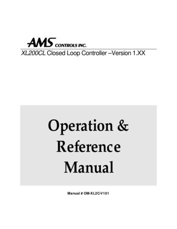
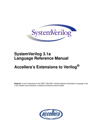
G and M-code reference10.4.3Coordinate SystemsThe machining system has an absolute coordinate system and 254 work offset (fixture)systems.You can set the offsets of tools by G10 L1 P X Z . The P word defines the tooloffset number to be set.You can set the offsets of the fixture systems using G10 L2 P X Y Z A B C The P word defines the fixture to be set. The X, Y, Z etc words are the coordinates for theorigin of for the axes in terms of the absolute coordinate system.You can select one of the first seven work offsets by using G54, G55, G56, G57, G58, G59.Any of the 255 work offsets can be selected by G59 P (e.g. G59 P23 would selectfixture 23). The absolute coordinate system can be selected by G59 P0.You can offset the current coordinate system using G92 or G92.3. This offset will thenapplied on top of work offset coordinate systems. This offset may be cancelled with G92.1LetterABCDFGHIJKLMNOPQRSTUVWXYZMeaningA-axis of machineB-axis of machineC-axis of machinetool radius compensation numberfeedrategeneral function (see Table 5)tool length offset indexX-axis offset for arcsX offset in G87 canned cycleY-axis offset for arcsY offset in G87 canned cycleZ-axis offset for arcsZ offset in G87 canned cyclenumber of repetitions in cannedcycles/subroutineskey used with G10miscellaneous function (see Table 7)line numberSubroutine label numberdwell time in canned cyclesdwell time with G4key used with G10feed increment in G83 canned cyclerepetitions of subroutine callarc radiuscanned cycle retract levelspindle speedtool selectionSynonymous with ASynonymous with BSynonymous with CX-axis of machineY-axis of machineZ-axis of machineFigure 10.2 - Word initial lettersRev 1.84-A210-9Using Mach3Mill
G and M-code Referenceor G92.2.You can make straight moves in the absolute machine coordinate system by using G53 witheither G0 or G1.10.5Format of a LineA permissible line of input code consists of the following, in order, with the restriction thatthere is a maximum (currently 256) to the number of characters allowed on a line. an optional block delete character, which is a slash "/" . an optional line number. any number of words, parameter settings, and comments. an end of line marker (carriage return or line feed or both).Any input not explicitly allowed is illegal and will cause the Interpreter to signal an error orto ignore the line.Spaces and tabs are allowed anywhere on a line of code and do not change the meaning ofthe line, except inside comments. This makes some strange-looking input legal. Forexample, the line g0x 0. 12 34y 7 is equivalent to g0 x 0.1234 y7Blank lines are allowed in the input. They will be ignored.Input is case insensitive, except in comments, i.e., any letter outside a comment may be inupper or lower case without changing the meaning of a line.10.5.1Line NumberA line number is the letter N followed by an integer (with no sign) between 0 and 99999written with no more than five digits (000009 is not OK, for example). Line numbers maybe repeated or used out of order, although normal practice is to avoid such usage. A linenumber is not required to be used (and this omission is common) but it must be in theproper place if it is used.10.5.2Subroutine labelsA subroutine label is the letter O followed by an integer (with no sign) between 0 and99999 written with no more than five digits (000009 is not permitted, for example).Subroutine labels may be used in any order but must be unique in a program althoughviolation of this rule may not be flagged as an error. Nothing else except a comment shouldappear on the same line after a subroutine label.10.5.3WordA word is a letter other than N or O followed by a real value.Words may begin with any of the letters shown in figure 11.2. The table includes N and Ofor completeness, even though, as defined above, line numbers are not words. Severalletters (I, J, K, L, P, R) may have different meanings in different contexts.A real value is some collection of characters that can be processed to come up with anumber. A real value may be an explicit number (such as 341 or -0.8807), a parametervalue, an expression, or a unary operation value. Definitions of these follow immediately.Processing characters to come up with a number is called "evaluating". An explicit numberevaluates to itself.10.5.3.1 NumberThe following rules are used for (explicit) numbers. In these rules a digit is a singlecharacter between 0 and 9. A number consists of (1) an optional plus or minus sign, followed by (2) zero tomany digits, followed, possibly, by (3) one decimal point, followed by (4) zero tomany digits - provided that there is at least one digit somewhere in the number.Using Mach3Mill10-10Rev 1.84-A2
G and M-code reference There are two kinds of numbers: integers and decimals. An integer does not have adecimal point in it; a decimal does. Numbers may have any number of digits, subject to the limitation on line length.Only about seventeen significant figures will be retained, however (enough for allknown applications). A non-zero number with no sign as the first character is assumed to be positive.Notice that initial (before the decimal point and the first non-zero digit) and trailing (afterthe decimal point and the last non-zero digit) zeros are allowed but not required. A numberwritten with initial or trailing zeros will have the same value when it is read as if the extrazeros were n
G and M-code Reference Using Mach3Mill 10 -4 Rev 1.84-A 2 10. Mach 2 G- and M-code language reference This section defines the language (G-codes etc.) that are understood and . control the compromise involved in turning corners because a real machine has a