Transcription
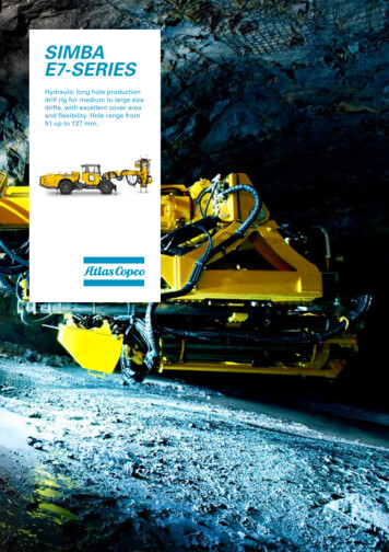
Oil Pool Fire ExperimentTAKAAKI YAMAGUCHI and KENJI WAKASAPetroleum Association of Japan1-9-4, Ohtemachi, Chiyoda-kuTokyo, 100 JapanABSTRACTIt is important to know the behavior of a large-scale oil pool fire, so alarge-scale oil pool fire experiment was carried on in JAPAN on May 30, 1981.It was carried out by filling excavated storage tanks measuring 30 m, 50 m and80 m in diameter each with water of about 200 mm in depth, floating kerosene toa depth of about 20 mm above the water and burning the kerosene.Measurements were made on the flame temperature, radiant heat, partialradiant heat, burning rate of a hydrocarbon pool fire, composition of gaseouscombustion products, naturally-induced airflow velocity and flame shape, sevenitems in all.The experiment results clearly indicate that the results of a small-scaleexperiment on a storage tank whose diameter is less than 10 m cannot be extrapolated to a large-scale oil pool fire.INTRODUCTIONThe oil pool fire experiment conducted this time was mainly aimed atclarifying the behavior of a large-scale oil pool fire with emphasis on theanalogy due to the sizes of storage tanks, and at examining the validity of theconventional danger evaluation based on the extrapolation of the results of asmall-scale experiment.The experiment was conducted at the Higashi-Fuji Exercise Field of theGround Self-Defense Force in Gotenba City, Shizuoka Prefecture on May 30, 1981with the participation of the Petroleum Association of Japan and PetrochemicalIndustry Association and the cooperation of shizuoka Prefecture.Formulation of the plan, guidance to execution and analysis of results ofthe experiment were commissioned to the Safety Engineering Association. TheAssociation established an Oil Pool Fire Experiment Committee consisting of 13experts to accomplish the task.PreparationThe experiment was carried out using excavated storage tanks of 30 m, 50 mand 80 m in diameter and by burning kerosene. The specifications and arrangement of the fuel tanks are shown in Fig. 1. Since the fuel was floated on theFIRE SAFETY SCIENCE-PROCEEDINGS OF THE FIRST INTERNATIONAL SYMPOSIUMCopyright International Association for Fire Safety Science911
water in the tank, the bottom of each fuel tank was covered with polyethylenesheeting to prevent water leakage.Kerosene was used as fuel for the following reasons: If crude oil with awide boiling-point range had been used, it would have caused changes in fluidcomposition due to evaporation during combustion, and no regular combustionwould be obtainable, resulting in difficulty of comparison of combustion characteristics. It was desirable to have a thicker layer of fuel in order to prolong the steady state of combustion, but it was determined to use a fuel layerof about 20 mm due to various restrictions, and this layer of fuel was floatedon the surface of water of about 200 mm in depth.1.Fuel tank specificationsTank descriptionAverage diameterTank height30 m tank30.04 m0.45 m0.25 m50 m tank50.02 m0.45 m0.25 m80 m tank80.07 m0.45 m0.25 mFree boardDIf1.I.htn\\Sectional view of fuel tank2.Fuel tank layout80 m fuel tank50 m fuel tank150 t waterstorage tankMeasurementcenterill-- ---FIGURE 1.30 m fuel tankSpecifications and layout of fuel tanks912-Road - - - -
IgnitionDue to the reasons that kerosene with a higher ignition point was used asfuel and it was necessary to cause the ignited fire to grow into a completeconflagration within as short a time as possible, small amounts of naphtha weremade to flow out of several points on the oil surface and ignited electricallyusing ignition balls.1.Ignition positionSince the thickness of kerosene was 20 rom and thin, it was necessary towholly burn kerosene for a short time after ignition so that the whole burning time would be made long.After pre-test results, it was found that liquid surface falling speed wasabout 2.1 rom/min and fire propagation speed was 3 to 4 m/min.The fire became a conflagration in 3 minutes after ignition.Kerosene consumption until then was thought to be about 2 rom on the averagefor all tanks. Kerosene of 18 rom or above was consumed when a conflagrationoccurs.Since fire propagation speed was 3 to 4 m/m, it was assumed that fire wouldexpand to 9 to 12 m in 3 minutes.The position and number of ignition points were determined, so that anyparts of the tank can be within about 10 m from the ignition position. Asa result, it was determined that 50 m tank should ignite at 4 points and80 m tank would ignite at 11 points. It was determined that the 30 m tankshould ignite at central 1 point in order to measure the fire propagationspeed.2.Ignition facilitiesSince it was difficult to ignite directly to kerosene, it was determinedthat ignition should be made by a small quantity of naphtha and ignitionballs to the extent of which influence would not given to the burning properties of kerosene.The head tank of ignition naphtha was installed at the place 5 to 10 m awayfrom the edge of each tank. The pre-test was made so that the naphthaquantity, which flowed out of respective outlets, would be about 500 ml/min.The height of the head tank was set so that its bottom would be 1 m higherfrom the outlet. Outlets, to which naphtha would flow from the head tank,were installed to the ignition equipment. They were connected with the PVCtube. Outlets were set facing upward direction at about 5 em above theliquid.The circumference of outlets was covered with cotton cloth hung from above.When the stop valve opened, which had been installed to the head tank containing naphtha, naphtha flowed out of outlets. Part of naphtha was impregna.ted into cotton cloth and remaining naphtha was mixed with kerosene in thetank. Ignition balls were set into cotton cloth so that naphtha would notbe directly placed. The switch of ignition balls was installed at D/4 outside the tank and ignition balls of respective tanks were designed to beoperated by setting one switch. Naphtha of 2500 ml per outlet was placed913
into the head tank so that naphtha of 500 ml for each minute per outletwould flow for 5 minutes.The number of head tanks was 30. One head tank each was installed for 50 mtank and 2 head tanks were installed for 80 m tank.3.Ignition proceduresPVC tubes were made full of naphtha beforehand so that naphtha would flowout from outlets at the same time when the valve was opened. The valve ofthe head tank was opened 1 minute before ignition. One minute after naphthawas discharged, the switch of ignition balls was turned ON and ignitionballs were caused to generate.According to this operation, ignition balls would be ignited, naphtha, whichwas impregnated into cotton cloth, would burn, kerosene mixed with naphthawould be lit and, further, fire would propagate to kerosene of the wholetank.MeasurementMeasurements were made on many items including the flame temperature, radiant heat, partial radiant heat, burning rate of the hydrocarbon pool fire, composition of gaseous combustion products, naturally-induced airflow velocity andflame shape.1.Flame temperature measurementTemperaturesbustion weretions in theD/4, and D/22.in the liquid and on and above the liquid surface during commeasured by installing sheath-type thermocouples at six locacenter of each tank and four locations at positions of DIS,CD: tank diameter) from the center, 18 locations in all.Radiant heat measurementRadiant heat from the flames was measured outside the fuel tank and on theliquid surface in the fuel tank. Measurements were made by installing radiant heat meters at positions of lD, 2D, 3D, and 4D from the center in eachtank for measuring outside the fuel tank, and by installing liquid-levelradiant heat meters at three points in the 80 m tank and at one point eachin 50 m and 30 m tanks for measuring on the liquid surface.3.Partial radiant heat measurementTo find out the magnitudes of radiant heat from various portions of flames,partial radiant heat was measured by installing radiant heat meters, whoseheat receiving surface was partially shielded, at a position of 2D from thecenter of each tank.4.Measurement of burning rate of hydrocarbon pool fireThe burning rate of fuel was measured by the liquid level descending rate.The average descending rate of the entire liquid level was measured at onepoint in each tank, while regional liquid level descending rates were measured at four points in the 80 m tank, two points in the 50 m tank and onepoint in the 30 m tank.914
Further, a video camera was installed at the center of the 50 m tank tomonitor the liquid level condition and liquid level descending rate duringcombustion.5.Measurement of composition of gaseous combustion productsTo find out the detailed burning condition during an oil conflagration,gases on the liquid surface and in the flames were sucked in and collectedfrom seven points in each tank, and concentrations of carbon monoxide,carbon dioxide, hydrocarbon and oxygen contained therein were analyzed bygas chromatograph. In addition, oxygen concentration was continuously measured using an oxygen concentration meter separately from the gas chromatograph.6.Measurement of naturally-induced airflow velocityThe velocity of the naturally induced airflow generated by the oil fire wasmonitored by propeller and bilam type anemometers installed at eight pointseach in each tank to measure the wind direction and velocity near the edgeof each tank.7.Flame shape measurementTo clarify the behavior of an oil conflagration including the height andshape of flames, the burning state in each tank was recorded by a 16 mmmovie camera and a video camera.ResultsExperiments with the 30 m tank (Experiment No.1) and 50 m tank (ExperimentNo.2) were carried out as planned under conditions of near calm, but the experiment with the 80 m tank (Experiment No.3) was conducted under windy conditions, and some points which were slightly different from the original plan suchas deviation of the oil layer on the water surface occurred.The present combustion experiments used unprecedently large-scale storagetanks, and measurements also employed new techniques such as observation ofliquid level variation by a submerged video camera, and measurements of the regional liquid level descending rate and partial radiant heat of flames, therebyobtaining many valuable experiment results. Major findings from the experimentsare enumerated below.1.In the 1st experiment, naphtha burned up at the same time when ignitionballs switch was turned ON, and just after that, the liquid surface beganburning. In the 2nd experiment, cotton naphtha at all 4 points burned upand the liquid surface began burning simultaneous when ignition balls switchwas turned ON. In the 3rd experiment, cotton cloth naphtha was ignited atonly 6 points due to strong wind.Three points out of them were set on the water surface where there was nooil, because the oil surface inclined to part of the burning tank due to thewind; hense fire propagation did not occur to the liquid surface and thefire was put out immediately after the flow of naphtha. Where the pointswere set on the liquid surface, the liquid surface was ignited immediately.In the 1st and 2nd experiments, a conflagration was made in about 3 minutesas scheduled. In the 3rd experiment, propagation down the wind side was in2 to 3 minutes. The whole surface on the wind side where there was keroseneburned in about 5 minutes after ignition.915
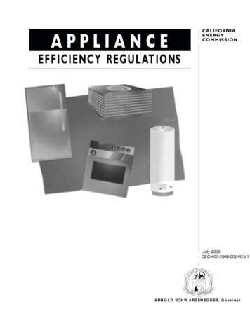
2.As analysis results of burning gas constituents, only 1 time of the resultconcerning the 80 m tank was shown. This was due to the fact that since1) kerosene in the 80 m tank was blown away towards the wind side by thewind, 2) about 1/2 of the kerosene surface only burned, 3) the kerosenesurface severely inclines, 4) the sample introduction section completely wasexposed in the air, measurement became meaningless; hence this part wasomitted.In the continuously recorded results of oxygen concentration in respectivetanks, it was observed that turbulence was caused by cock operation forsampling. From the positional relationship between the fire condition atnearly the time when sampling was made and the sample introduction section,it can be thought that in the 30 and 50 m tanks, gas constituents in theflames can be sampled, but in the 80 m tank, the sample introduction sectionis exposed very much in the air. When we consider the positional relationbetween the condition of the fire nearly at the time, when sampling is made,and the sample introduction section, we find that we have probably been ableto sample gas constituents in the fire for at 30-m and SO-m tanks, but thesample introduction section is quite extensively exposed to air at the 80 mtank.3.Light emission of the flames was not dependent upon the sizes of storagetanks, but became the maximum at a height 0.8 to 1.0 times the tank diameterlength. Such flames developed a pattern of respiration with a period ofseveral seconds, and the period became longer as the storage tank size increased.4.The maximum temperature of the flames was obtained near the center of thetank and reached 1,400 to 1,800 C. This value did not vary with the sizesof tanks, but was slightly higher than that of a crude oil fire.10,000 .;::NS7,0005,0005,000 om,"nkl[50m tank'i ,OOO- ,.2,000C\Io 0'M3,0002,000.wC\I 'Ms;:i.1,000.w700'M C\I'M"dC\I5001\01,0001\700500300P':200rtI\ '1\300FIGURE 2. Relation between radiant heat and dimensionless distance under calmconditions (L is the distance from tank center to radiation meter)916
5.The rece v ng quantity of radiant heat along the ground surface--when compared with dimensionless distance LID which was obtained by dividing thedistance from the tank center L by storage tank diameter D--suddenlydropped as LID increased, and the heat receiving quantity, the dimensionlessdistance being equal, did not collate with the value obtained by conventional predictive calculation, and sharply decreased as the size of the tankincreases.6.Oil level descending rate due to combustion was about 4.7 mm/min on theaverage of the entire oil surface, and did not appear to be dependent ontank sizes. On the other hand, the regional liquid level descents variedwith locations and time within the range of 2 to 7 mm/min, and were relatedto the movements of flames near the oil surface.7.Naturally-induced airflow velocity necessary for burning was greater at theposition higher than the ground surface and indicated the value of severalm/s. This rate dropped as the tank size increased and showed cyclic variation as the respiration of the flames. Further, the oil surface developedripples even during calm owing to this naturally-induced airflow by combustion.8.Near the liquid level at the tank center during a conflagration, oxygensupply was minimal, and oxygen concentration became higher at a positionhigh above the liquid level. As a result, oxygen deficiency occurred atthe center portion, and steam which had evaporated from the liquid surfacedeveloped pyrolysis and generated low-molecular-weight combustible gasessuch as methane.9.During combustion, heat transfer from flames to the liquid surface wasmainly performed by radiant heat transfer, and convective heat transfer wasonly about 10% of the radiant heat transfer.10.Slanting of flames due to winds was at about 30 from horizontal at thelower part of the flames in Experiment No.3 in which wind velocity variedbetween 5 to 10 m/s. This slanting angle increased to about 70 at theupper part of the flames.11.The wind did not greatly affect the maximum temperature of flames. Radiant heat from flames when it was windy showed a great difference dependingupon the wind receiving direction. It became the maximum in the rightangle direction with the wind direction and the minimum on the windwardside.General ConclusionsThese results will be analyzed in detail in the future. Some items of theexperiment results are important, because they suggest that the results of thesmall-scale experiment with a tank having a diameter of less than 10 m, as theyare, cannot be extrapolated to an oil conflagration. In particular, the finding c?ncerning radiant heat in Item 3. indicates that since the heat receivingquantity decreases as the storage tank size increases, the dimensionless distance being equal, it is not appropriate to compare radiation heat danger uniformly by the dimensionless distance and that the calculation of radiant heatby the conventionally used danger prediction calculation method requires reassessment, because such calculation gives over-estimation of several times asmuch as the measured value, thereby suggesting that the said finding has animportant meaning in practice.917
The measured values of radiant heat obtained by the present experiment arecompared with calculated values obtained by the conventional calculation methodas follows:Measured and calculated values of radiant heat intensityBurnt tankdiameterDistance from burnttank centerRadiant heat intensityMeasured value Calculated valueEc Kcal/m 2hEm* Kcal/m2hRatioEm/Ec%30 53504850 24* Average during calmThe present experiment is expected to increase in value as research progress in this field, and actual application of the experiment results will playimportant roles in the practical and research aspects in the future.REFERENCES1.Japan Society for Safety Engineering: The Report of the Oil Pool FireExperiment, J.S.S.E., Yokohama, Japan, 1981.2.Yumoto, T.: Journal of Japan Society for Safety Engineering, J.S.S.E.,Yokohama, Japan, lQ: 3, 143, 1971.3.Yumoto, T.: Journal of Japan Society for Safety Engineering, J.S.S.E.,Yokohama, Japan, : 1, 58, 1977.4.Yumoto, T., Nakagawa, N., and Sato, K.: Journal of Japan Society forSafety Engineering, J.S.S.E., Yokohama, Japan, 21: 1, 30, 1982.5.Yamaguchi, T., Konishi, S., and Yamamoto, Y.: Journal of Japan Societyfor Safety Engineering, J.S.S.E., Yokohama, Japan, : 4, 215, 1982.6.Kashio, T., and Akita, K.: Proceedings of the 13th Symposium of SafetyEngineering, Japan Society for Safety Engineering, Japan, 81, 1983.918
the experiment were commissioned to the Safety Engineering Association. The Association established an Oil Pool Fire Experiment Committee consisting of 13 experts to accomplish the task. Preparation The experiment was carried out using excavated storage tanks of 30 m, 50 m and 80 m in diameter and by burning kerosene. The specifications and .