Transcription
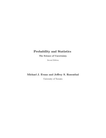
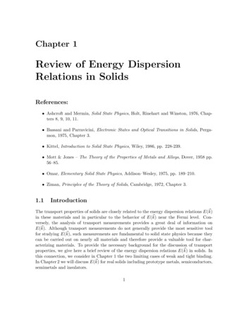
1ENGG2400 Mechanics of Solids 1Lab 2 - TorsionLocation: Undergraduate Teaching Laboratory, Room 214A, J18 Willis AnnexReport Submission: Due on Friday, November 8th, 2019 (Week 08)Report writing: Use the template provided for writing your reportMethod: Online submission (submission box will be provided)1.INTRODUCTIONThis lab activity involves two testings, namely tension and torsion tests. The tension test aims to identify the principlesof tension testing, practice testing skills and interpret the experimental results of the provided materials when failedunder tension. The test will require students to investigate the relationships between the Load, Displacement, Young’smodulus, Yield strength and Strain.Figure 1. Dimensions of the tensile specimenThe torsion test aims to identify the mechanical properties of a cylindrical specimen under angular motion. The testwill require students to quantitatively investigate the relationships between torque and the angle of twist, modulus ofrigidity (shear modulus), yield shear strength and shear strain.Torsion Laboratory T3 2019 ENGG2400
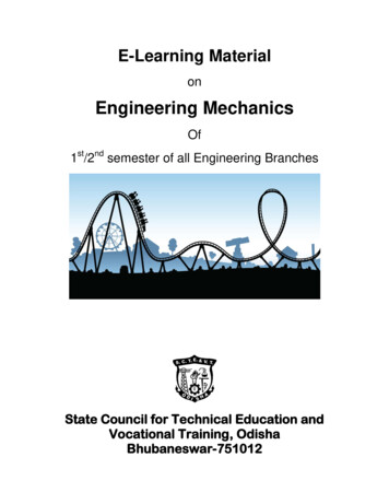
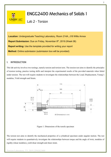
2140 mm76 mm parallel11.3 mm across flatsor12 mm across flatsNominal 6 mm diameterFigure 2. Dimensions of the torsion specimen2. FUNDAMENTAL THEORYThis section shows the fundamental theory and equations used for calculations in the forthcoming experiments.2.1. Normal stress and strain, and Young’s ModulusNormal stress is the ratio of normal force to the cross-sectional area. It is found byFAσ (1)Normal strain is the change in length of a material over its original length. It is found byε LL(2)Young’s Modulus is the ratio of the normal stress divided by the normal strain on a material. It is a measure of thestiffness of a material. It is found byE σε(3)2.2. Modulus of Rigidity or Shear Modulus (G)The shear modulus of modulus of rigidity is a measure of the rigidity of the material when in ‘shear’ – when it istwisting. It is a ratio of the shear stress and the shear strain of the material:G τγBoth formulae (3) and (4) only describe the material behaviour when it is stressed within its elastic region.Torsion Laboratory T3 2019 ENGG2400(4)
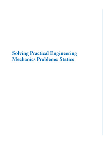
32.3. Polar Moment of Inertia (J)This is an equation that shows the ability of a circular cross-section beam or specimen to resist torsion (twisting). Ahigher polar moment of inertia (J) shows that the beam or specimen can resist a higher torsion or twisting force. Thediameter of the beam determines polar moment of inertia (J):J π D432(5)The general equation for the torque in a circular cross-section beam or specimen is:T Gθ Jl(6)2.4. Torque (𝑇𝑇)Figure 3. Torque (twisting force)The twisting force (torque) at the end of a specimen is the moment of a force on the torque arm – calculated by Digitalload meter (DL1):T F Torque Arm Length(7)2.5. Shear Stress (𝜏𝜏) and Shear Strain (𝛾𝛾)The theoretical shear stress for a solid circular bar isτ TD2J(8)The theoretical shear strain for the solid circular bar isγ τ Grθl(9)A rearrangement of the Shear Modulus therefore gives:G Torsion Laboratory T3 2019 ENGG2400(TD ) / ( 2 J )( rθ ) / l(10)
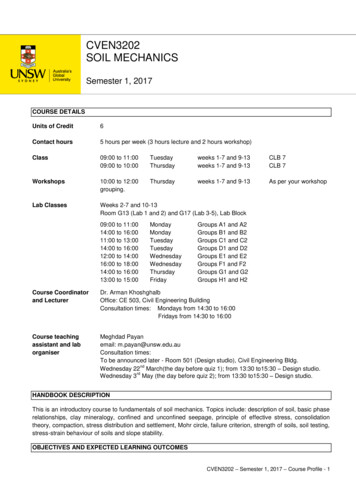
42.6. NotationSymbolDescriptionUnitsAAream2MApplied momentNmFForceNLTotal length of a specimenmlTest lengthmTTorqueNmJPolar moment of inertiam4GShear modulusNm-2DDiameter of specimenmrRadius of specimenmτShear stressNm-2γShear strainθAngle of twistRadiansσNormal stressNm-2EYoung’s modulusNm-2εNormal strain3. Failure theory for ductile materialsWhen an engineer is faced with the problem of design using a specific material, it becomes important to place anupper limit on the state of stress that defines the material’s failure. If the material is ductile, failure is usually specifiedby the initiation of yielding. A yield criterion is a hypothesis defining the limit of elasticity in a material and the onsetof plastic deformation under any possible combination of stresses. Students are strongly recommended to refer to p.524-527 of Mechanics of Materials 9th ed. by R. C. Hibbeler.Torsion failures are different from failures under tension and cause negligible elongation or deformation. Thecharacteristic of the fracture surface under torsion is related to the state of stress at the element on the specimensurface, which is shown in Figure 4. It can be seen that the maximum shear stresses exist along two planes, which areperpendicular to each other. One is perpendicular to the longitudinal (x) axis and another is aligned parallel to thelongitudinal (x) axis. The principal stresses σ1 and σ3 are inclined at 45o to the longitudinal axis and have theirmagnitudes equal to those of the shear stresses. The principal stress σ1 is tensile while the principal stress σ3 iscompressive. The intermediate stress σ2 is zero under torsion.Torsion Laboratory T3 2019 ENGG2400
5Figure 4. State of stresses in torsion (Dieter, G. E. Mechanical metallurgy, 1988, McGraw-Hill)The maximum-shear-stress theory (Tresca yield criterion) can be used to predict the failure stress of a ductile materialsubjected to any type of loading. The theory states that yielding of the material begins when the absolute maximumshear stress in the material reaches the shear stress that causes the same material to yield when it is subjected only toabsaxial tension. Therefore, to avoid failure, it is required that τ maxin the material must be less than or equal toσY2,where σ Y is determined from a simple tension test.The maximum-distortion-energy theory (von Mises failure criterion) explains that yielding in a ductile material occurswhen the distortion energy per unit volume of the material equals or exceeds the distortion energy per unit volume ofthe same material when it is subjected to yielding in a simple tension test. The value of von Mises stress needed tocause yield can be determined from the tensile yield stress σ Y . The shear yield stress can similarly be found byinserting the principal stresses corresponding to a state of pure shear. Therefore, to avoid failure, it is required thatabsin the material must be less than or equal toτ maxTorsion Laboratory T3 2019 ENGG2400σY3.
64. Experiment 1: Tensile testingThe aim of this experiment is to find the yield and ultimate tensile strengths and the corresponding normal strains ofthe test material. Experiment 1 enables the prediction of the maximum shear stress that will be measured fromExperiment 3 using the failure theories.Specimen Material:Specimen Gauge Length:Young’s Modulus (E):Yield strength (σY):Predicted maximum shear stress (τmax) using Maximum-Shear-Stress Theory:Predicted maximum shear stress (τmax) using Maximum-Distortion-Energy Theory:DigitalChange inDisplacementExtensometerStressLengthForce (kN)indicator readingreading (mm)(mm)(mm)000Table 1. Experiment 1 result tableTorsion Laboratory T3 2019 ENGG2400Strain
74.1. Analysis of resultsi.Plot a graph of stress σ (vertical axis) against strain ε (horizontal axis) from the first test (with theextensometer).ii.On your plot, mark the yield point using the 0.2% offset yield strength. The 0.2% offset yield strength isdefined as the stress that will cause a permanent plastic strain deformation of 0.2%. You will need to calculateYoung’s modulus by taking the gradient of the graph in the elastic (linear) region.iii.Plot a graph of stress against strain from the second test (without the extensometer, data from Moodle). Findand mark the ultimate tensile strength.Torsion Laboratory T3 2019 ENGG2400
85. Experiment 2: Shear Modulus (with Torsiometer)The aim of this experiment is to find the shear modulus for the specimen material and compare it with given values.This experiment is also to familiarise students with the equipment and its sensitivity in the specimen’s elastic region.5.1. Analysis of resultsi.Find the polar moment of inertia for your specimen using the following equation:J π D432ii. Find the shear stress τ and strain γ using the following equations for each set of results and complete Table 1.τ γ τTD2J Grθliii. Plot a graph of shear stress (vertical axis) against shear strain (horizontal axis).iv. Find the gradient of your chart. The value will be the shear modulus (G) for your specimen.Specimen Material:Specimen Gauge Length:Polar Moment of Inertia (J):Modulus of Rigidity (G) from this experiment:Angular Displacement(0.001” 0.001 rad)Torque Table 2. Experiment 2 results tableTorsion Laboratory T3 2019 ENGG2400
96. Experiment 3: Ultimate shear strength (without Torsiometer)The aim of this experiment is to find the yield and ultimate shear strength and the corresponding shear strain of the testmaterial.Specimen Material:Specimen Gauge Length:Ultimate Shear Strength:Modulus of Rigidity (G) from this experiment:Angle (degrees)Torque (Nm)Angle 702018025303540455060Table 3. Experiment 3 results tableTorsion Laboratory T3 2019 ENGG2400Torque (Nm)
106.1. Analysis of resultsi.Plot a graph of shear stress (vertical axis) against shear strain (horizontal axis).ii.On your chart, mark the yield point (upper and lower yield point for some steel specimens).iii.Find the polar moment of inertia for your specimen.iv.Find the shear stress at the yield point.v.On your chart, mark the ultimate point.vi.Find the ultimate shear stress and strain.vii.Find the modulus of rigidity using this graph.viii.Estimate the yield strength of the material in tension using the failure criteria.7.Report requirements and marking criteria (6 marks)i.Complete Table 1, 2 and 3 with appropriate units. (0.5 marks)ii.Present detailed calculations in the report. Make appropriate comments including the whole procedure of yourcalculations. Make all calculations clear, legible and professional looking. (1 mark)iii.Stick the graphs where necessary (showing the required marked points). (1.5 marks)iv.Write discussion and conclusion (section below) based on the results. (2 marks)E.g. Explain the possible error, including the prediction of the maximum shear stress, in both theexperimentations and analysis thereafter. Discuss the reason why you have a significant difference in G fromtwo different tests if there is any. Discuss the differences of the fracture manners between tension and torsiontests and theory behind them.v.Overall formatting and quality of report (1 mark)Torsion Laboratory T3 2019 ENGG2400
118. Appendix8.1. Introduction to the rigs8.1.1. Introduction to the Tensile testing machineThe Universal Testing Machine is a rigid four-column frame that holds a hydraulic ram on a ram support plate. Theram pushes a cross member upwards. The cross member pulls two steel tie-bars upwards. The tie-bars pull a loadingplatform upwards. The joints at the top and bottom of the tie-bars can move, to allow self-alignment. This gives purelyaxial loading. Halfway up each tie-bar is a strain-gauged force sensor. The outputs of each force sensor connect to atwo-in, one-out connection box. The output of the connection box connects to the DL1 Digital Load Meter.Figure 5. The 100kN Universal Testing MachineThe DL1 Digital Load Meter shows the force (stress) applied to a specimen and has a socket for connection toTecQuipment’s VDAS. VDAS will allow data acquisition with the use of a suitable computer (not supplied). It alsohas a ‘peak hold’ – to store and display the maximum force that it measures during a test.The Displacement Indicator fixes to one of the columns and measures the movement (displacement) of the loadingplatform (or other moving parts) during test. The indicator shows the displacement in millimetres and has a socket forconnection to TecQuipment’s VDAS.To find the Young’s Modulus of a tensile test specimen (in the elastic region) you need accurate measurement ofstrain over a small range. Students clamp the Extensometer around the specimen, then apply a gradually increasingload. They record the small values of extension while the specimen stretches in its elastic region. Students mustremove the Extensometer if they are to continue the test outside the specimen’s elastic region (e.g. destructive tests).8.1.2. Introduction to the Torsion testing machineThe Torsion Testing Machine you are going to use is a laboratory-scale machine. It shows the torque (stress) and twist(strain) in a specimen under twisting moment. In Experiment 1 (Test 1), which is conducted within the elastic limit ofTorsion Laboratory T3 2019 ENGG2400
12the material, you will determine the Shear Modulus, G. Three different material specimens will be used. InExperiment 2 (Test 2), the test will continue until the specimen ruptures in shear and you will be able to determine theShear Yield strength and also the ultimate Shear Stress and Strain. Earlier you used the Universal Testing Machine forTensile strength of materials. The torsion testing machine gives similar pattern of results for the Shear characteristicsof materials.Figure 6. The 30 Nm torsion testing machineThe gearbox is manually turned, with a 60:1 reduction ratio and a sliding output shaft. A transducer measures thenumber of turns of the Gearbox. The gearbox turns clockwise and anticlockwise to apply clockwise and anticlockwisetorsion. However, the normal direction for your test is clockwise.(a)(b)(c)Figure 7. (a) Digital angle meter, (b) Digital load meter and (c) TorsiometerThe Digital Angle Meter (DA1) calculates and shows the angle of twist at the Gearbox end of the specimen. Thismeter automatically converts the amount of turns of the Gearbox output shaft into an angle in degrees.The Digital Load Meter (DL1) calculates and shows the torque at the Torque Measurement Head. This meterautomatically multiplies the known torque arm length by the force from a load cell force sensor. This meter has a‘Peak Hold’ button, so that the meter will store the maximum reading of torque that it measures.For increased accuracy of torsion measurement at small angles (less than 2degree) of twist in the elastic region (Test1) you may use the Torsiometer as shown above. This is a precision instrument that fits to 6 mm diameter specimensto measure the angular displacement (twist) over a known ‘gauge length’ of 50 mm.Torsion Laboratory T3 2019 ENGG2400
13Note that the Torsiometer only works for small twist angles. This is good for measurements over the small angles oftwist for the elastic region of specimen materials.8.2. Experimental procedureExperiment 1 (Tension)8.2.1. Accurately measure and record the dimensions of your specimen.8.2.2. Connect up and switch on the DL1 Digital Load Meter, and allow it to warm up the strain gauges in theforce sensors and use your pump to fully raise the ram.8.2.3. Find the two sets of ‘chucks’ that hold the tensile test specimens. They each have three parts – an inner partin two matching halves (collets) and one outer part. Fit the outer of the chucks to both the top and bottomball joints in the tensile test area. Use the small bar to stop the ball joint turning while you tighten the chunkas shown Figure 8.Figure 8. Fit the Outer part of the Chucks and use the Small bar to stop the Ball Joint Turning8.2.4. Fit the collets to one end of the specimens and fit the specimen in its collets to the bottom outer chuck and fiton of the large pins to secure the whole assembly as shown in Figure 9.Figure 9. Fit the Collets to One End of the Specimen, then Fit it to the Bottom Chuck8.2.5. Fit the collets to the top of the specimen, and slowly lower the ram. As the ram lowers, align the top colletsinto the top outer chuck and fit the other pin. Make sure the specimen is not under any tension. It should befree to move by a small amount.Torsion Laboratory T3 2019 ENGG2400
148.2.6. Remove the transit bar from the Extensometer. The Extensometer has two parts that slide against each other.Push them firmly together to give the correct gauge length of 50 mm. Put the extensometer around thethinnest part of the specimen and carefully tighten the pinch screws onto the specimen. Hold the two halvestogether while you do this. Do not over-tighten the pinch screws, as they may cause localised stresses whichcould cause the specimen to fail at a lower stress than expected.8.2.7. Fit the Digital Displacement Indicator to the front left column as shown in Figure 10. Slide the wholeassembly up the column until the magnet clamps underneath the loading platform. Hold the display carefullyand adjust the assembly to give at least 60 mm of upward movement.Figure 10. Fit the Digital Displacement Indicator and adjust for 60 mm of upward movement8.2.8. On the Digital Load Meter, press the button to zero the display. If you need to record the maximum force,press the ‘Peak hold’ button.8.2.9. Use your pump to raise the ram slowly to remove the looseness in the specimen. While you do this, watchthe Load Meter display and stop when the meter just begins to register a force. Re-zero the load meter, zerothe Digital Displacement Indicator and the indicator on the Extensometer.8.2.10. Fit the guard around the test area. In steps of 0.5 kN, increase the ram force slowly –never decrease theforce, as your results will become wrong. At each step, record the load, and the readings from both theDisplacement Indicator and the Extensometer. Continue increasing the ram force until you note that thespecimen has started to ‘yield’.8.2.11. Remove the Extensometer and re-fit the guard around the machine. Refit the transit bar in the Extensometerto keep it together while it is not used. Continue until the specimen fails.Experiment 2 (Torsion)8.2.12. Accurately measure and record the dimensions of your specimen.8.2.13. Check the distance across the flats at the ends of your specimen, then choose the correct sockets to fit yourspecimen (12 mm or 3/16” Whitworth)8.2.14. Fit the sockets to the torque head and the gearbox output, shown in Figure 11.Torsion Laboratory T3 2019 ENGG2400
15Figure 11. Fit the sockets to the torque head and the gearbox output8.2.15. Fit the Torsiometer to the specimen, shown in Figure 12: Use a hexagon tool to loosen the hexagon fixings and remove the Transit Bar from the Mechanismof the Torsiometer. Slide the Specimen into the gauge. Push the gauge together so that it grips the specimen at exactly 50 mm gauge length Tighten the fixings. They must hold the specimen securely, but not so tight that they damage thespecimen. Push the Digital Indicator into its holder and gently tighten the thumbscrew. Set the distance from the holder to the measurement arm as approximately 3 mm and tighten thelarge locking ring.8.2.16. Switch on the Digital Indicator and set its display to zero.8.2.17. Fit the specimen with Torsiometer to the sockets. Slide the gearbox output shaft along so that the specimensends fit fully into each socket.8.2.18. Switch on both digital meters, and press their ‘Press to zero’ buttons. You cannot fit the guard when theTorsiometer is used.8.2.19. To remove any mechanical error (or ‘backlash’), slowly turn the gearbox hand wheel until the load displaystarts to show a small value of torque, then use the ‘Press to zero’ buttons to set all displays to zero.8.2.20. Carefully press the Torsiometer button that sets its display to zero.8.2.21. In this test, you will only stress the specimen in its elastic region, so you must increase the angle of twist in0.005 radian steps up to a maximum of 0.030 radians. Record the torque at each step on Table 2. Do notexceed 0.030 radians for the TecQuipment specimens. You will stress them past their elastic limit.(aTorsion Laboratory T3 2019 ENGG2400
16(b)(c)(d)(e)Figure 12. Procedures of fitting the specimen with TorsiometerExperiment 3 (Torsion)8.2.22. Accurately measure and record the dimensions of your specimen.8.2.23. Check the distance across the flats at the ends of your specimen, then choose the correct sockets to fit yourspecimen (12 mm)8.2.24. Fit the sockets to the torque head and the gearbox output, shown in Figure 11.8.2.25. Fit the specimen to the sockets. Slide the gearbox output shaft along so that the specimens ends fit fully intoeach socket, shown in Figure 13.Figure 13. Fit the specimen8.2.26. Switch on both digital meters, and press their ‘Press to zero’ buttons.Torsion Laboratory T3 2019 ENGG2400
178.2.27. Fit the clear guard around the specimen as this test takes the specimens to destruction.8.2.28. To remove any mechanical error (or ‘backlash’), slowly turn the gearbox hand wheel until the load displaystarts to show a small value of torque, then use the ‘Press to zero’ buttons to set all displays to zero.8.2.29. Press the ‘Peak Hold’ button of the Load Meter so that it records the maximum torque in the test.8.2.30. For the first part of the test the specimen will be stressed in its elastic region, so you must increase the angleof twist in small steps of 1 degree. Turn the hand wheel at a constant rate in one direction only. Do not turnit backwards.8.2.31. At each angle, record the angle and the torque value on Table 2 (next page).8.2.32. After approximately 10 degrees, the specimen has passed its upper yield point. You can now increase theangle size between measurements to larger increments. (5 degrees increment up to 50 degrees and 10 degreeincrement up to 180 degrees).8.2.33. You may now continue to increase the angle until the specimen breaks. You still need to record the angleand the torque value at each angle on Table 3.Torsion Laboratory T3 2019 ENGG2400
4. Experiment 1: Tensile testing The aim of this experiment is to find the yield and ultimate strengthtensiles and the corresponding normal strains of the test material. Experiment 1 enables the prediction of the maximum shear stress that will be measured from Experiment 3 using the failure theories.