Transcription
VSD Series IIInstallation ManualNew Information added May 2017
VSD Series IIImportant Notice–Please ReadThe product discussed in this literature is subject to terms and conditions outlinedin Johnson Controls Inc. selling policies. The sole source governing the rights andremedies of any purchaser of this equipment is the relevant Johnson Controls Inc.selling policy.NO WARRANTIES, EXPRESS OR IMPLIED, INCLUDING WARRANTIES OFFITNESS FOR A PARTICULAR PURPOSE OR MERCHANTABILITY, ORWARRANTIES ARISING FROM COURSE OF DEALING OR USAGE OF TRADE,ARE MADE REGARDING THE INFORMATION, RECOMMENDATIONS ANDDESCRIPTIONS CONTAINED HEREIN. In no event will Johnson Controls Inc. orEaton Electrical Inc. be responsible to the purchaser or user in contract, in tort(including negligence), strict liability or otherwise for any special, indirect, incidentalor consequential damage or loss whatsoever, including but not limited to damage orloss of use of equipment, plant or power system, cost of capital, loss of power,additional expenses in the use of existing power facilities, or claims against thepurchaser or user by its customers resulting from the use of the information,recommendations and descriptions contained herein.The information contained in this manual is subject to change without notice.Cover Photo: Johnson Controls VSD Series II DriveWarranty and Liability InformationIn accordance with details on next page, Johnson Controls Inc. warrants the productdelivered in the Johnson Controls shipping package to be free from defects inmaterial and workmanship, under normal use and service. Products that fail duringthis period will be repaired or replaced at Johnson Controls discretion, with thesame or a functionally equivalent product, provided the original purchaser (A) returnsthe failed product, and (B) provides proof of original date of purchase. The originalpurchaser of the product must obtain a Johnson Controls Return MaterialAuthorization (RMA) number prior to returning any defective product. (Whenpurchased through an Authorized Distributor, the Distributor should supply anRMA number to their customer.)The maximum liability of this warranty is limited to the purchase price of theproduct. In no event, regardless of cause, shall Johnson Controls Inc. or EatonElectrical Inc. be liable (a) for penalties or penalty clauses of any description, or (b)for certification not otherwise specifically provided herein and/or indemnification ofpurchaser or others for costs, damages or expenses, each arising out of or related tothe product or services of any order or (c) for any damages resulting from loss ofprofits, use of products or for any incidental indirect or consequential damages,even if advised of the possibility of such damages.VSD Series II LIT-12011772—May 2017 www.johnsoncontrols.comi
VSD Series IIStandard WarrantySubject to the limitations and conditions stated herein, that all new Series II VSDproducts shall be free from defects in material and workmanship and shall delivertheir rated output as indicated on the nameplates for a period of thirty (30) monthsfrom date of shipment.This warranty shall provide coverage for replacement parts only and does not coverfailure or damage due to storage, installation, operation or maintenance not inconformance with Johnson Controls recommendations and industry standardpractice or due to accident, misuse, abuse or negligence. In addition, this warrantydoes not cover reimbursement for labor, including any removal/installation expenseswhich may be incurred in connection with repair or replacement, unless otherwiseagreed upon by Johnson Controls.Warranty with Certified Start-UpProvided the equipment is commissioned by an authorized EATON serviceprovider (including individuals certified through Johnson Controls VSD Start-up/Commissioning Certification Training), JOHNSON CONTROLS warrants that allnew Series II VSD products shall be free from defects in material and workmanshipand shall deliver their rated output as indicated on the nameplates for a period ofthirty-nine (39) months from date of shipment.This warranty shall provide coverage for replacement parts and on-site labor,including any removal/installation expenses associated with the warranty claim.Return Authorization/General ReturnsProduct DescriptionCreditOpen, Type 1, Type 12 Drives100%Intellipass and Intellidisconnect Type 1, Type 12 and Type 3R Enclosed Branded Drives85%Custom Engineered Drives and Obsolete Products0%1. JOHNSON CONTROLS agrees to accept VSD Open products for return andwithout penalty or restocking charge. JOHNSON CONTROLS will issue a 100%credit—provided the product is in its original unopened package and is returnedwithin 120 days of receipt of product by JOHNSON CONTROLS.2. JOHNSON CONTROLS agrees to accept VSD Intellipass and IntellidisconnectDrives with a 15% restocking fee provided the product is in its originalunopened package and is returned within 120 days of receipt of product byJOHNSON CONTROLS.3. JOHNSON CONTROLS shall promptly refund or credit said customer for anyand all payments made by the buyer for such product(s). The buyer will beresponsible for all freight charges associated with products authorized for returnto JOHNSON CONTROLS.iiVSD Series II LIT-12011772—May 2017 www.johnsoncontrols.com
VSD Series IISupport ServicesThe goal of Johnson Controls is to ensure your greatest possible satisfaction with theoperation of our products. We are dedicated to providing fast, friendly, and accurateassistance. Whether it’s by phone, fax, or e-mail, you can access support informationlisted below.You should contact your local Johnson Controls Sales Representative for product pricing,availability, ordering, expediting, and repairs.Web SiteUse the Johnson Controls Web site to find product information.Web Site Addresswww.johnsoncontrols.com – HVAC Controls – Variable Speed DrivesJohnson Controls Product Sales OperationCall the Johnson Controls PSO Team if you need assistance with placing an order, stockavailability or proof of shipment, expediting an existing order, emergency shipments, productprice information and returns (including warranty returns).Voice: 1-800-ASK-JNSN [275-5676] (US); 1-800-321-4023 (CA)FAX: 1-800-356-1191 (US); 1-800-321-4024 (CA)Support Hours of Operation: Monday–Friday, 6:30 a.m.–5:30 p.m. CST(No evening or weekend Customer Service hours).If you are in the U.S. or Canada, you can take advantage of our toll-free line for technicalassistance. Technical support engineers are available for calls during regular business hours.Johnson Controls Field Support Center1-888-281-3792 Monday–Friday, 7:30 a.m.–5:30 p.m. CSTemail: CGFieldSupportCenter@jci.comFor emergency assistance, contact: Eaton Technical Resource CenterVoice: 877-ETN-CARE (386-2273) (8:00 a.m.–5:00 p.m. EST)FAX: 828-651-0549e-mail: TRC@Eaton.comVSD Series II LIT-12011772—May 2017 www.johnsoncontrols.comiii
VSD Series IITable of ContentsSAFETYBefore Commencing the Installation . . . . . . . . . . . . . . . . . . . . . . . . . . . . . . . . .Definitions and Symbols . . . . . . . . . . . . . . . . . . . . . . . . . . . . . . . . . . . . . . . . . .Hazardous High Voltage . . . . . . . . . . . . . . . . . . . . . . . . . . . . . . . . . . . . . . . . . .Warnings and Cautions . . . . . . . . . . . . . . . . . . . . . . . . . . . . . . . . . . . . . . . . . . .viiviiiviiiviiiENGINEERINGIntroduction . . . . . . . . . . . . . . . . . . . . . . . . . . . . . . . . . . . . . . . . . . . . . . . . . . . .Electrical Power Network . . . . . . . . . . . . . . . . . . . . . . . . . . . . . . . . . . . . . . . . .Safety and Switching . . . . . . . . . . . . . . . . . . . . . . . . . . . . . . . . . . . . . . . . . . . . .EMC Measures . . . . . . . . . . . . . . . . . . . . . . . . . . . . . . . . . . . . . . . . . . . . . . . . .Motor and Application . . . . . . . . . . . . . . . . . . . . . . . . . . . . . . . . . . . . . . . . . . . .12456SYSTEM OVERVIEWComponent Identification . . . . . . . . . . . . . . . . . . . . . . . . . . . . . . . . . . . . . . . . .Selection Criteria . . . . . . . . . . . . . . . . . . . . . . . . . . . . . . . . . . . . . . . . . . . . . . . .Proper Use . . . . . . . . . . . . . . . . . . . . . . . . . . . . . . . . . . . . . . . . . . . . . . . . . . . . .Maintenance and Inspection . . . . . . . . . . . . . . . . . . . . . . . . . . . . . . . . . . . . . . .Storage . . . . . . . . . . . . . . . . . . . . . . . . . . . . . . . . . . . . . . . . . . . . . . . . . . . . . . .Service and Warranty . . . . . . . . . . . . . . . . . . . . . . . . . . . . . . . . . . . . . . . . . . . .91112121313VSD SERIES II OVERVIEWHow to Use this Manual . . . . . . . . . . . . . . . . . . . . . . . . . . . . . . . . . . . . . . . . . .Receiving and Inspection . . . . . . . . . . . . . . . . . . . . . . . . . . . . . . . . . . . . . . . . . .Catalog Number Selection . . . . . . . . . . . . . . . . . . . . . . . . . . . . . . . . . . . . . . . . .Power Ratings and Product Selection . . . . . . . . . . . . . . . . . . . . . . . . . . . . . . . .Electrical Installation . . . . . . . . . . . . . . . . . . . . . . . . . . . . . . . . . . . . . . . . . . . . .1414161719INSTALLATION REQUIREMENTSStandard Mounting Instructions . . . . . . . . . . . . . . . . . . . . . . . . . . . . . . . . . . . .NEMA Type 1/12 Open Drives (1–250 hp) . . . . . . . . . . . . . . . . . . . . . . . . . . . .Power Wiring Selection . . . . . . . . . . . . . . . . . . . . . . . . . . . . . . . . . . . . . . . . . . .Cable Routing . . . . . . . . . . . . . . . . . . . . . . . . . . . . . . . . . . . . . . . . . . . . . . . . . .Control Board . . . . . . . . . . . . . . . . . . . . . . . . . . . . . . . . . . . . . . . . . . . . . . . . . . .EMC Installation . . . . . . . . . . . . . . . . . . . . . . . . . . . . . . . . . . . . . . . . . . . . . . . .Checking the Cable and Motor Insulation . . . . . . . . . . . . . . . . . . . . . . . . . . . . .20212225293038APPENDIX ATechnical Data . . . . . . . . . . . . . . . . . . . . . . . . . . . . . . . . . . . . . . . . . . . . . . . . . .39APPENDIX BCable Power and Motor Wiring Guidelines . . . . . . . . . . . . . . . . . . . . . . . . . . . .43APPENDIX CDimension Drawings . . . . . . . . . . . . . . . . . . . . . . . . . . . . . . . . . . . . . . . . . . . . .46ADDENDUM A - added February 2017New Control Board Update . . . . . . . . . . . . . . . . . . . . . . . . . . . . . . . . . . . . . . . .525-600V Offering . . . . . . . . . . . . . . . . . . . . . . . . . . . . . . . . . . . . . . . . . . . . . . . .ivVSD Series II LIT-12011772—May 2017 www.johnsoncontrols.com6570
VSD Series IIList of FiguresDrive System (PDS) . . . . . . . . . . . . . . . . . . . . . . . . . . . . . . . . . . . . . . . . . . . . . . . . . . . .AC Power Networks with Grounded Center Point(TN-/TT Networks) . . . . . . . . . . . . . . . . . . . . . . . . . . . . . . . . . . . . . . . . . . . . . . . . . .EMC Environment and Category . . . . . . . . . . . . . . . . . . . . . . . . . . . . . . . . . . . . . . . . . .Parallel Connection of Several Motors to One Frequency Inverter . . . . . . . . . . . . . . . .Example of a Motor Ratings Plate . . . . . . . . . . . . . . . . . . . . . . . . . . . . . . . . . . . . . . . . .Star and Delta Circuit Types . . . . . . . . . . . . . . . . . . . . . . . . . . . . . . . . . . . . . . . . . . . . . .V/Hz-Characteristic Curve . . . . . . . . . . . . . . . . . . . . . . . . . . . . . . . . . . . . . . . . . . . . . . .Bypass Motor Control (Example) . . . . . . . . . . . . . . . . . . . . . . . . . . . . . . . . . . . . . . . . . .VSD Series II . . . . . . . . . . . . . . . . . . . . . . . . . . . . . . . . . . . . . . . . . . . . . . . . . . . . . . . . .Description of the VSD Series II . . . . . . . . . . . . . . . . . . . . . . . . . . . . . . . . . . . . . . . . . .Block Diagram, Elements of VSD Series II Frequency Inverters . . . . . . . . . . . . . . . . . .Selection Criteria . . . . . . . . . . . . . . . . . . . . . . . . . . . . . . . . . . . . . . . . . . . . . . . . . . . . . .Rating Plate . . . . . . . . . . . . . . . . . . . . . . . . . . . . . . . . . . . . . . . . . . . . . . . . . . . . . . . . . .Approval Sticker . . . . . . . . . . . . . . . . . . . . . . . . . . . . . . . . . . . . . . . . . . . . . . . . . . . . . . .Carton Labels (U.S. and Europe) . . . . . . . . . . . . . . . . . . . . . . . . . . . . . . . . . . . . . . . . . .Mounting Space . . . . . . . . . . . . . . . . . . . . . . . . . . . . . . . . . . . . . . . . . . . . . . . . . . . . . . .Input Power and Motor Cable Stripping Lengths . . . . . . . . . . . . . . . . . . . . . . . . . . . . . .Wiring the VSD . . . . . . . . . . . . . . . . . . . . . . . . . . . . . . . . . . . . . . . . . . . . . . . . . . . . . . .VSD Series II Variable Speed Drive . . . . . . . . . . . . . . . . . . . . . . . . . . . . . . . . . . . . . . . .EMC-Compliant Setup (Example: VSD Series II) . . . . . . . . . . . . . . . . . . . . . . . . . . . . . .Cable Description . . . . . . . . . . . . . . . . . . . . . . . . . . . . . . . . . . . . . . . . . . . . . . . . . . . . . .Locations of the EMC-Jumpers in Frames FS4 to FS6 . . . . . . . . . . . . . . . . . . . . . . . . .Three-Phase Input Connection . . . . . . . . . . . . . . . . . . . . . . . . . . . . . . . . . . . . . . . . . . . .Connection to Power Section . . . . . . . . . . . . . . . . . . . . . . . . . . . . . . . . . . . . . . . . . . . .Ground Connection . . . . . . . . . . . . . . . . . . . . . . . . . . . . . . . . . . . . . . . . . . . . . . . . . . . .Removing the Jumper, FS5 as Example . . . . . . . . . . . . . . . . . . . . . . . . . . . . . . . . . . . .Grounding Bar Location, FS8 . . . . . . . . . . . . . . . . . . . . . . . . . . . . . . . . . . . . . . . . . . . . .Removing the EMC Jumper, FS7 and FS8 . . . . . . . . . . . . . . . . . . . . . . . . . . . . . . . . . . .Detaching the DC Grounding Bus Bar from Frame, FS7 . . . . . . . . . . . . . . . . . . . . . . . .Molex Connector Placement, FS9 . . . . . . . . . . . . . . . . . . . . . . . . . . . . . . . . . . . . . . . . .Removing the EMC Jumper, FS9 . . . . . . . . . . . . . . . . . . . . . . . . . . . . . . . . . . . . . . . . . .Product Modified Sticker . . . . . . . . . . . . . . . . . . . . . . . . . . . . . . . . . . . . . . . . . . . . . . . .FS4 Dimension Drawing . . . . . . . . . . . . . . . . . . . . . . . . . . . . . . . . . . . . . . . . . . . . . . . .FS4 Dimension Drawing Flange Mount . . . . . . . . . . . . . . . . . . . . . . . . . . . . . . . . . . . . .FS5 Dimension Drawing . . . . . . . . . . . . . . . . . . . . . . . . . . . . . . . . . . . . . . . . . . . . . . . .FS5 Dimension Drawing Flange Mount . . . . . . . . . . . . . . . . . . . . . . . . . . . . . . . . . . . . .FS6 Dimension Drawing . . . . . . . . . . . . . . . . . . . . . . . . . . . . . . . . . . . . . . . . . . . . . . . .FS6 Dimension Drawing Flange Mount . . . . . . . . . . . . . . . . . . . . . . . . . . . . . . . . . . . . .FS7 Dimension Drawing . . . . . . . . . . . . . . . . . . . . . . . . . . . . . . . . . . . . . . . . . . . . . . . .FS7 Dimension Drawing Flange Mount . . . . . . . . . . . . . . . . . . . . . . . . . . . . . . . . . . . . .FS8 Dimension Drawing IP00 . . . . . . . . . . . . . . . . . . . . . . . . . . . . . . . . . . . . . . . . . . . .FS8 Dimension Drawing IP2154 Flange Mount . . . . . . . . . . . . . . . . . . . . . . . . . . . . . . .FS8 Dimension Drawing Flange Mount . . . . . . . . . . . . . . . . . . . . . . . . . . . . . . . . . . . . .FS9 Dimension Drawing . . . . . . . . . . . . . . . . . . . . . . . . . . . . . . . . . . . . . . . . . . . . . . . .FS9 Dimension Drawing IP2154 . . . . . . . . . . . . . . . . . . . . . . . . . . . . . . . . . . . . . . . . . .FS9 Dimension Drawing Flange Mount . . . . . . . . . . . . . . . . . . . . . . . . . . . . . . . . . . . . 737374647484950515253545556575859VSD Series II LIT-12011772—May 2017 www.johnsoncontrols.comv
VSD Series IIList of TablesIdentification on the Residual-Current Circuit-Breakers . . . . . . . . . . . . . . . . . . . . . . . . .Assignment of Frequency Inverters to Example Motor Circuit . . . . . . . . . . . . . . . . . . .Maintenance Measures and Intervals . . . . . . . . . . . . . . . . . . . . . . . . . . . . . . . . . . . . . .VSD Series II Open Drives . . . . . . . . . . . . . . . . . . . . . . . . . . . . . . . . . . . . . . . . . . . . . . .NEMA Type 1/IP21 or NEMA Type 12/IP54 . . . . . . . . . . . . . . . . . . . . . . . . . . . . . . . . .NEMA Type 1/IP21 or NEMA Type 12/IP54 . . . . . . . . . . . . . . . . . . . . . . . . . . . . . . . . .VSD Series II Variable Speed Drive Option Boards . . . . . . . . . . . . . . . . . . . . . . . . . . . .Space Requirements for Mounting the VSD Series II VSD and Airflow . . . . . . . . . . . .Mounting Drive Dimensions . . . . . . . . . . . . . . . . . . . . . . . . . . . . . . . . . . . . . . . . . . . . . .Power Connection Tightening Torque . . . . . . . . . . . . . . . . . . . . . . . . . . . . . . . . . . . . . .Spacing Between Parallel Motor Cables . . . . . . . . . . . . . . . . . . . . . . . . . . . . . . . . . . . .Maximum Cable Length by Frame Size without DV/DT Protected C2 Ratings . . . . . . .Input Power and Motor Cable Stripping and Wire Lengths . . . . . . . . . . . . . . . . . . . . . .International EMC Protection Cable Requirements . . . . . . . . . . . . . . . . . . . . . . . . . . . .VSD Series II Technical Data . . . . . . . . . . . . . . . . . . . . . . . . . . . . . . . . . . . . . . . . . . . . .Standard I/O Board . . . . . . . . . . . . . . . . . . . . . . . . . . . . . . . . . . . . . . . . . . . . . . . . . . . .Relay Board 1 . . . . . . . . . . . . . . . . . . . . . . . . . . . . . . . . . . . . . . . . . . . . . . . . . . . . . . . .Relay Board 2 . . . . . . . . . . . . . . . . . . . . . . . . . . . . . . . . . . . . . . . . . . . . . . . . . . . . . . . .North America Cable and Fuse Sizes—208–240 Vac Ratings . . . . . . . . . . . . . . . . . . . .North America Cable and Fuse Sizes—380–480 Vac Ratings . . . . . . . . . . . . . . . . . . . .International Cable and Fuse Sizes 380–480 Vac Ratings . . . . . . . . . . . . . . . . . . . . . . .viVSD Series II LIT-12011772—May 2017 9414242434445
VSD Series IISafetyWarning!Dangerous Electrical Voltage!Before Commencing the Installation Disconnect the power supply of the device Ensure that devices cannot be accidentally restarted Verify isolation from the supply Earth and short circuit the device Cover or enclose any adjacent live components Follow the engineering instructions (IL04020001E) for thedevice concerned Only suitably qualified personnel in accordance withEN 50110-1/-2 (VDE 0105 Part 100) may work on thisdevice/system Before installation and before touching the device ensurethat you are free of electrostatic charge The functional earth (FE, PES) must be connected to theprotective earth (PE) or the potential equalization. Thesystem installer is responsible for implementing thisconnection Connecting cables and signal lines should be installed sothat inductive or capacitive interference does not impairthe automation functions Install automation devices and related operating elementsin such a way that they are well protected againstunintentional operation Suitable safety hardware and software measures shouldbe implemented for the I/O interface so that an opencircuit on the signal side does not result in undefinedstates in the automation devices Ensure a reliable electrical isolation of the extra-lowvoltage of the 24V supply. Only use power supply unitscomplying with IEC 60364-4-41 (VDE 0100 Part 410) orHD384.4.41 S2 Deviations of the input voltage from the rated value mustnot exceed the tolerance limits given in the specifications,otherwise this may cause malfunction and dangerousoperation Emergency stop devices complying with IEC/EN 60204-1must be effective in all operating modes of the automationdevices. Unlatching the emergency-stop devices must notcause a restartDevices that are designed for mounting in housings orcontrol cabinets must only be operated and controlledafter they have been installed and with the housing closed.Desktop or portable units must only be operated andcontrolled in enclosed housings Measures should be taken to ensure the proper restart ofprograms interrupted after a voltage dip or failure. Thisshould not cause dangerous operating states even for ashort time. If necessary, emergency-stop devices shouldbe implemented Wherever faults in the automation system may causeinjury or material damage, external measures must beimplemented to ensure a safe operating state in the eventof a fault or malfunction (for example, by means ofseparate limit switches, mechanical interlocks, and so on) Depending on their degree of protection, variable speeddrives may contain live bright metal parts, moving orrotating components, or hot surfaces during andimmediately after operation Removal of the required covers, improper installation, orincorrect operation of motor or variable speed drive maycause the failure of the device and may lead to seriousinjury or damage The applicable national accident prevention and safetyregulations apply to all work carried out on live variablespeed drives The electrical installation must be carried out inaccordance with the relevant regulations (for example,with regard to cable cross sections, fuses, PE) Transport, installation, commissioning, and maintenancework must be carried out only by qualified personnel(IEC 60364, HD 384 and national occupational safetyregulations) Installations containing variable speed drives must beprovided with additional monitoring and protective devicesin accordance with the applicable safety regulations.Modifications to the variable speed drives using theoperating software are permitted All covers and doors must be kept closed during operation To reduce hazards for people or equipment, the user mustinclude in the machine design measures that restrict theconsequences of a malfunction or failure of the drive(increased motor speed or sudden standstill of motor).These measures include: Other independent devices for monitoring safety-relatedvariables (speed, travel, end positions, and so on) Electrical or non-electrical system-wide measures(electrical or mechanical interlocks) Never touch live parts or cable connections of thevariable speed drive after it has been disconnected fromthe power supply. Due to the charge in the capacitors,these parts may still be live after disconnection. Fitappropriate warning signsVSD Series II LIT-12011772—May 2017 www.johnsoncontrols.comvii
VSD Series IISafetyDefinitions and SymbolsWarnings and CautionsWARNINGThis symbol indicates high voltage. It calls yourattention to items or operations that could be dangerousto you and other persons operating this equipment.Read the message and follow the instructions carefully.CAUTIONWhen selecting the cable cross-section, take the voltagedrop under load conditions into account.The consideration of other standards (for example, VDE 0113or VDE 0289) is the responsibility of the user.CAUTIONThis symbol is the “Safety Alert Symbol.” It occurs witheither of two signal words: CAUTION or WARNING, asdescribed below.WARNINGIndicates a potentially hazardous situation which, if notavoided, can result in serious injury or death.The specified minimum PE conductor(EN 50178, VDE 0160) must be maintained.WARNINGWith frequency inverters, only AC/DC sensitive residualcurrent circuit breakers (RCD type B) are to be used(EN 50178, IEC 755).CAUTIONIndicates a potentially hazardous situation which, if notavoided, can result in minor to moderate injury, or seriousdamage to the product. The situation described in theCAUTION may, if not avoided, lead to serious results.Important safety measures are described in CAUTION (aswell as WARNING).CAUTIONDebounced inputs may not be used in the safety circuitdiagram.Residual current circuit breakers (RCD) are only to beinstalled between the AC power supply network and thefrequency inverter.CAUTIONHazardous High VoltageWARNINGMotor control equipment and electronic controllers areconnected to hazardous line voltages. When servicingdrives and electronic controllers, there may be exposedcomponents with housings or protrusions at or aboveline potential. Extreme care should be taken to protectagainst shock.Stand on an insulating pad and make it a habit to use onlyone hand when checking components. Always work withanother person in case an emergency occurs. Disconnectpower before checking controllers or performingmaintenance. Be sure equipment is properly grounded. Wearsafety glasses whenever working on electronic controllers orrotating machinery.viiicross-sectionsDebounced inputs may not be used in the safety circuitdiagram.If you are connecting multiple motors on one frequencyinverter, you must design the contactors for the individualmotors according to utilization category AC-3.Selecting the motor contactor is done according to the ratedoperational current of the motor to be connected.CAUTIONDebounced inputs may not be used in the safety circuitdiagram.A changeover between the frequency inverter and the inputsupply must take place in a voltage-free state.VSD Series II LIT-12011772—May 2017 www.johnsoncontrols.com
VSD Series IIWARNINGCAUTIONThe frequency inverter outputs (U, V, W) must not beconnected to the input voltage (destruction of thedevice, risk of fire).CAUTIONDebounced inputs may not be used in the safety circuitdiagram.Debounced inputs may not be used in the safety circuitdiagram.Ground contact currents in frequency inverters are greaterthan 3.5 mA (AC). According to product standard IEC/EN61800-5-1, an additional equipment grounding conductormust be connected, or the cross-section of the equipmentgrounding conductor must be at least 0.39 in2 (10 mm2).Switch S1 must switch only when frequency inverter T1 is atzero current.WARNINGCarry out wiring work only after the frequency inverterhas been correctly mounted and secured.WARNINGThe components in the frequency inverter’s powersection remain energized up to five (5) minutes after thesupply voltage has been switched off (intermediatecircuit capacitor discharging time).Pay attention to hazard warnings!WARNINGElectric shock hazard—risk of injuries!Carry out wiring work only if the unit is de-energized.CAUTIONDANGER5 MINWARNINGDebounced inputs may not be used in the safety circuitdiagram.Do not perform any modifications on the AC drive whenit is connected to mains.Fire hazard!Only use cables, protective switches, and contactors thatfeature the indicated permissible nominal current value.CAUTIONBefore connecting the AC drive to mains make sure that theEMC protection class settings of the drive are appropriatelymade.VSD Series II LIT-12011772—May 2017 www.johnsoncontrols.comix
VSD Series IIxVSD Series II LIT-12011772—May 2017 www.johnsoncontrols.com
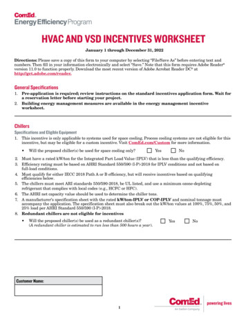
EngineeringEngineeringIntroductionThis chapter describes the most important features in the energy circuit of a drive system (PDS Power Drive System) that you should take into consideration in your project planning.Drive System (PDS)L1L2햲L3PEItemNumber1Network configuration, input voltage, input frequency,interaction with p.f. correction systems2Breakers, fuses, and cable cross-sectionsI I I 3Protection of persons and domestic animals withresidual-current protective devicesRCD4Input contactor5Frequency inverter: mounting, installation; power connection;EMC measures; circuit examples6Motor reactor, dv/dt filter, sine-wave filter7Motor protection; thermistor8Cable lengths, motor cables, shielding (EMC)9Motor and application, parallel operation of multiple motorson a frequency inverter, bypass circuit; DC braking햳햴Description햵L1 L2 L3 PE햶PE UVW#햷햸PES햹PESM3 햺VSD Series II LIT-12011772—May 2017 www.johnsoncontrols.com1
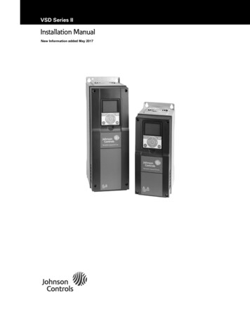
EngineeringElectrical Power NetworkInput Connection and ConfigurationInput Voltage and FrequencyThe VSD Series II frequency inverters can be connected andoperated with all control-point grounded AC power networks(see IEC 60364 for more information).The standardized input voltages (IEC 60038, VDE017-1) forenergy suppliers (EVU) guarantee the following conditions atthe transition points:AC Power Networks with Grounded Center Point(TN-/TT Networks)L1L2L3NPEL1L2L3PENWhile planning the project, consider a symmetricaldistribution to the three external conductors, if multiplefrequency inverters with single-phase supplies are to beconnected. The total current of all single-phase consumers isnot to cause an overload of the neutral conductor(N-conductor).The connection and operation of frequency inverters toasymmetrically grounded TN networks (phase-groundedDelta network “Grounded Delta”, USA) or non-grounded orhigh-resistance grounded (over 30 ohms) IT networks is onlyconditionally permissible.If the VSD Series II frequency inverters are connected to anasymmetrically grounded network or to an IT network(non-grounded, insulated), the internal interferencesuppression filter must be disconnected (unscrew the screwmarked EMC, see “Installation in IT System” on Page 33).The required filtering for electromagnetic compatibility (EMC)is then no longer present. Deviation from the rated value of voltage: maximum 10% Deviation in voltage phase balance: maximum 3% Deviation from rated value of the frequency:maximum 4%The broad tolerance band of the VSD Series II frequencyinverter considers the rated value for European as(EU: ULN 230V/400V, 50 Hz) and American as(USA: ULN 240V/480V, 60 Hz) standard voltages: 230V, 50 Hz (EU) and 240V, 60 Hz (USA) at HMX32 400V, 50 Hz (EU) and 480V, 60 Hz (USA) at HMX34For the bottom voltage value, the permitted voltage drop of4% in the consumer circui
VSD Series II VSD Series II LIT-12011772—May 2017 www.johnsoncontrols.com i Important Notice-Please Read The product discussed in this literature is subject to terms and conditions outlined in Johnson Controls Inc. selling policies.