Transcription
CHAPTER 1BOMBS, FUZES, AND ASSOCIATED COMPONENTSFunctioning time. The time required for a fuze todetonate after impact or a preset time.Bombs must be manufactured to withstandreasonable heat and be insensitive to the shock ofordinary handling. They must also be capable of beingdropped from an aircraft in a safe condition whenin-flight emergencies occur.Instantaneous. When the functioning time of afuze is 0.0003 second or less.Nondelay. When the functioning time of a fuze is0.0003 to 0.0005 second.Bomb detonation is controlled by the action of afuze. A fuze is a device that causes the detonation of anexplosive charge at the proper time after certainconditions are met. A bomb fuze is a mechanical or anelectrical device. It has the sensitive explosive elements(the primer and detonator) and the necessarymechanical/electrical action to detonate the mainburster charge. A mechanical action or an electricalimpulse, which causes the detonator to explode, firesthe primer. The primer-detonator explosion is relayedto the main charge by a booster charge. This completesthe explosive train.Proximity (VT). The action that causes a fuze todetonate before impact when any substantial object isdetected at a predetermined distance from the fuze.Safe air travel (SAT). The distance along thetrajectory that a bomb travels from the releasing aircraftin an unarmed condition.BASIC FUZE THEORYFuzes are normally divided into two generalclasses—mechanical and electrical. These classes onlyrefer to the primary operating principles. They may besubdivided by their method of functioning or by theaction that initiates the explosive train—impact,mechanical time, proximity, hydrostatic, or long delay.Another classification is their position in thebomb—nose, tail, side, or multi-positioned.FUZE TERMINOLOGY AND BASICFUZE THEORYLEARNING OBJECTIVE: Describe theoperation of mechanical and electrical fuzes.Identify special safety features that areinherent in bomb fuzes.Mechanical FuzesThis chapter will introduce you to some of thecommon terms and acronyms associated with fuzesused in the Navy. Basic fuze theory, general classes offuzes, and the various types of fuzes are also discussedin this chapter.In its simplest form, a mechanical fuze is like thehammer and primer used to fire a rifle or pistol. Amechanical force (in this case, the bomb impacting thetarget) drives a striker into a sensitive detonator. Thedetonator ignites a train of explosives, eventually firingthe main or filler charge. A mechanical bomb fuze ismore complicated than the simple hammer and primer.For safe, effective operation, any fuze (mechanical orelectrical) must have the following design features:FUZE TERMINOLOGYSome of the most common fuze terms that youshould know are defined as follows:Arming time. The amount of time or vanerevolutions needed for the firing train to be aligned afterthe bomb is released or from time of release until thebomb is fully armed. It is also known as safe separationtime (SST). It must remain safe in stowage, while it ishandled in normal movement, and duringloading and downloading evolutions. It must remain safe while being carried aboardthe aircraft.Delay. When the functioning time of a fuze islonger than 0.0005 second. It must remain safe until the bomb is releasedand is well clear of the delivery aircraft (armingdelay or safe separation period).External evidence of arming (EEA). A means bywhich a fuze is physically determined to be in a safe orarmed condition.1-1
Depending upon the type of target, the fuze maybe required to delay the detonation of the bombafter impact for a preset time (functioningdelay). Functioning delay may vary from a fewmilliseconds to many hours.A shear-safe fuze does not become armed if itsarming mechanism is damaged or completely severedfrom the fuze body. The arming mechanism of the fuzeprotrudes from the bomb, and it might be severed fromthe fuze body if the bomb is accidentally dropped.Shear-safe fuzes give additional security for carrieroperations and for externally mounted bombs. It should not detonate the bomb if the bomb isaccidentally released or if the bomb is jettisonedin a safe condition from the aircraft.Delay arming mechanically or electrically slowsthe arming of the fuze. It keeps a fuze in the safecondition until the bomb falls far enough away from orlong enough from the aircraft to minimize the effects ofa premature explosion. Delay arming helps to makecarrier operations safe because a bomb accidentallyreleased during landing or takeoff ordinarily will nothave sufficient air travel, velocity, or time to fully armthe fuze.To provide these qualities, a number of designfeatures are used. Most features are common to alltypes of fuzes.Electrical FuzesElectrical fuzes have many characteristics ofmechanical fuzes. They differ in fuze initiation. Anelectrical impulse is used to initiate the electrical fuzerather than the mechanical action of arming vanerotation.REVIEW NUMBER 1An electrical pulse from the delivery aircraftcharges capacitors in the fuze as the bomb is releasedfrom the aircraft. Arming and functioning delays areproduced by a series of resistor/capacitor networks inthe fuze. The functioning delay is electromechanicallyinitiated, with the necessary circuits closed by means ofshock-sensitive switches.The electric bomb fuze remains safe until it isenergized by the electrical charging system carried inthe aircraft. Because of the interlocks provided in therelease equipment, electrical charging can occur onlyafter the bomb is released from the rack or shackle andhas begun its separation from the aircraft; however, it isstill connected electrically to the aircraft's bomb armingunit. At this time, the fuze receives an energizingcharge required for selection of the desired arming andimpact times.Q1.Name the device that controls bombdetonation.Q2.The time or number of vane revolutionsneeded for the firing train to align after abomb is released is the .Q3.Describe the functioning time of a fuze.Q4.The distance along the trajectory that a bombtravels from the releasing aircraft in anunarmed condition is the .Q5.List the two basic classes of fuzes.Q6.Describe the basicmechanical fuze.Q7.What means is used to initiate an electricalfuze?Q8.List the three special safety features incorporated into fuzes.principleoftheSPECIAL SAFETY FEATURESMECHANICAL FUZESSome fuzes incorporate special safety features. Themost important safety features are detonator safe, shearsafe, and delay arming.LEARNING OBJECTIVE: Identify thevarious types of mechanical fuzes to includetheir physical description and functionaloperation.Detonator safe fuzes do not have the elements oftheir firing train in the proper position for firing untilthe fuze is fully armed. The elements remain firmlyfixed and out of alignment in the fuze body while thefuze is unarmed. This increases safety during shipping,stowing, and handling of the fuze. The arming action ofthe fuze aligns the firing train.There are many fuzes in use by the Navy today.Some of the commonly used fuzes are discussed in thisTRAMAN. To keep up with current fuzes, you shouldrefer to Aircraft Bombs, Fuzes, and AssociatedComponents, NAVAIR 11-5A-17, and Airborne Bomband Rocket Fuze Manual, NAVAIR 11-1F-2.1-2
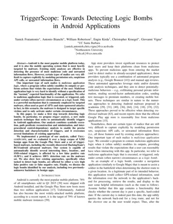
The fuze may be configured for a number ofpreselected arming and functioning delays needed by amission. There are nine arming delays from 2 to 18seconds in 2-second increments, and any combinationof six functioning delays from instantaneous to 250milliseconds (0.250 seconds) may be selected. Aninternal governor, driven by the permanently mountedarming vane, allows relatively constant arming times atrelease speeds ranging from 170 to over 525 knots.M904E2/E3/E4 MECHANICAL IMPACT NOSEFUZEThe M904 (series) fuze (fig. 1-1) is a mechanicalimpact nose fuze used in the Mk 80 (series) low-draggeneral-purpose (LDGP) bombs. The M904 (series)fuze is installed in the nose fuze well of the bomb andrequires the use of an adapter booster. The fuze isdetonator-safe, and it contains two observationwindows through which you can determine thesafe/arm condition of the fuze. There is no speciallocking feature designed into the fuze for shear safety ifthe bomb is accidentally dropped. However, detonationis unlikely if the collar (forward end of the fuze) issheared off by the accidental drop before arming iscomplete.Functioning times are determined by theinstallation of an M9 delay element. Any one of sixdelay elements may be installed. Each delay element isidentified by the functioning delay time stamped on theelement body—NONDELAY (instantaneous), 0.01,0.025, 0.05, 0.1, or 0.25 second.Figure 1-1.—Mechanical impact nose fuze M904 (series).1-3
significantly increases the cook-off time (table 1-1) ofthe bombs subjected to intense heat or flame.Physical DescriptionThe M904 (series) fuze contains approximately 11/2 ounces of tetryl in the booster, which is located atthe base of the fuze body. The entire fuze weighs about2 1/3 pounds and is 9 1/4 inches long.REVIEW NUMBER 1 ANSWERSThe M904E4 is a thermally protected fuze. It isespecially designed for use with the thermallyprotected Mk 80 (series) general-purpose bombs andthe thermally protected M148E1 adapter booster. ThisA1.A fuze controls bomb detonation.A2.The time or number of vane revolutionsneeded for the firing train to align after abomb is released is the arming time.Table 1-1.—MK 80/BLU Series Cook-Off TimesBombInitiatedReactionFuze BoosterInitiatedReaction*2 30Deflagrationto explosionDeflagrationto detonation(after 5minutes)10 008 00DeflagrationDeflagrationto detonation(after 12minutes)M904E2/E3with M148/T456 005 00M148T45(no fuze)3 04Mk 83 Mods/BLU-110thermallyprotectedM904E4 withM148E1Adapter,FMU-139/B,FMU-15210 008 49DeflagrationMk 84 Mods/BLU-117thermallyprotectedM904E4 withM148E1Adapter,FMU-139/B,FMU-15210 008 45Deflagrationto detonation(after actionTime(Min & Sec)ShortestReactionTimeBombH6 andPBXN109filledMk 82, 83, 84unprotectedAll3 30Mk 82 Mods/BLU-111M904E4 withM148E1Adapter,FMU-152,FMU-139Deflagrationto detonationDeflagrationto detonation(denotationmay occurafter 5minutes)Deflagrationto detonation(after 12minutes)* Fuze or booster initiated reaction. Frequency of detonation reaction is small.** Chips in exterior coating and/or groove for retarding fin cut to bare steel do not change cook-off time.1-4
A3.The time required for a fuze to detonate afterimpact or a preset time is known as thefunctioning time.A4.The distance along the trajectory that a bombtravels from the releasing aircraft in anunarmed condition is known as the safe airtravel (SAF).A5.The two basic classes of fuzes are electricaland mechanical.A6.The force used to initiate the mechanical fuzeis like the hammer and primer used to fire arifle. A mechanical force drives a striker intoa sensitive detonator.A7.An electrical impulse initiates an electricalfuze.A8.The three special safety features incorporatedinto fuzes are detonator safe, shear safe, anddelay arming features.the setting index locking pin and rotate the knurledarming delay setting knob until the white indexing lineis aligned with the desired arming delay time stampedon the nose retaining ring. The 2- and 4-second armingtimes are for use with retarded weapons, and are onlyset by removing the stop screw located next to thesetting index locking pin. Never try to reinstall thestop screw when either of these two settings areused. The stop screw may be reinstalled at any delaysetting of 6 seconds or more.IDENTIFICATION OF ARMED FUZES.—There are three conditions of the M904 fuze—safe,partially armed, and fully armed. You can verify thefuze conditions by looking through the two observationwindows in the fuze body (fig. 1-1). To check the fuzecondition, hold the fuze vertically and look through thewindows perpendicular to the fuze body. Look at table1-2. It shows you what you would see through theobservation windows of the M904E3/4 fuze at varioustime settings and fuze conditions.ARMING DELAY TIMES.—Arming delaytimes are inscribed into the face of the forward noseretaining ring. A white indexing line is scribed on theknurled delay setting knob below the arming vane. Thewhite indexing line must be matched to one of theindicated arming times to select the desired armingdelay. To select the required arming delay time, depressAlso, check the M904E4 to make sure the thermalsleeve is firmly bonded to the fuze collar and is notcracked.NOTE: If the safe condition of any fuze is indoubt, explosive ordnance disposal (EOD)personnel should be notified immediately.Table 1-2.—Indications for Determining Conditions of M904E3/4 Nose FuzesConditionUpper WindowLower Window18 SecondsWhite number "18" ongreen background.Vacant or dark incolor.6 SecondsWhite number "6" ongreen background.Partially Armed18 and 6 SecondsGreenbackgroundwith no numbersvisible. (If numbersappear at other than"18" or "6" secondsetting or if numbersdo not match settings,fuzeispartiallyarmed.)Vacant or dark incolor.ArmedAny setting. (Timesetting cannot bechanged.)*Red with black letter"A."(Some greenmay show at top ofwindow.)*Red with black Letter"A."SafeTime Setting1-5
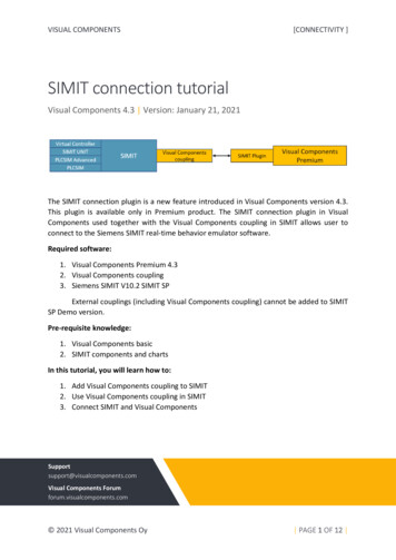
REVIEW NUMBER 2Functional DescriptionThe M904 fuze arms and functions by the rotationof the arming vane and alignment of its internalcomponents. When the fuze is released from theaircraft, the fuze arming wire is withdrawn from thefuze arming vane, and the arming vane is rotated by theairstream. Arming vane rotation is controlled by theconstant arming action of the governor in the fuze. Thearming vane continues to rotate until the preselectedarming delay period (2 to 18 seconds) elapses (ends).Once the arming delay period elapses, the firing train isin full alignment and ready to function.At impact, the forward part of the fuze body drivesthe striker body and firing pin down into the M9 delayelement. After the proper delay, the M9 delay ignitesthe relay, detonator, lead, and booster, which sets off themain charge.Q1.What kind of fuze is the M904?Q2.What bomb series is the M904 fuze used with?Q3.The M904 fuze has arming delays,which you can set for 2 to 18 seconds inincrements; there are any combination of functioning delays frominstantaneous to 250 milliseconds.Q4.The M904 is thermally protected. Why is thisimportant?Q5.Describe the means you use to check thecondition of the M904 fuze.Q6.If you can't tell if a fuze is "safe," you shouldnotify .Q7.The M904 arms and.functions131217A11511A16310NOTE2TOP OF BOMB CLUSTERROTATED 45 DEGREESCLOCKWISE FOR CLARITY14918568741.2.3.4.5.6.Fuze safe/arm indicatorTimer starting pinTimer starting pin bracketOption time setting adjustmentPrimary time setting adjustmentBand release stud and nut7.8.9.10.11.12.Fuze arming wireSafety pin assemblyImpellerImpeller band assemblyTime setting observation windowOption time pin13.14.15.16.17.18.Indicator observation windowNose fairing (reference)Option time wireRetainer slideClipSafety pin assembly guide tubeFigure 1-2.—Installed mechanical time fuze Mk 339 Mod 1 (with option time wire bomb clusters Mk 20 Mods 3, 4, and 6.1-6by
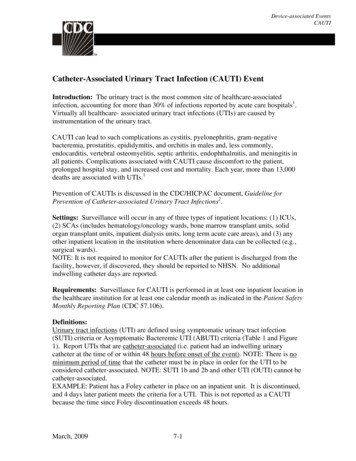
MK 339 MOD 1 MECHANICAL TIME FUZEA7.The Mk 339 Mod 1 mechanical time fuzes (fig.1-2) are used with dispenser weapons and have thefollowing characteristics:Physical Description Nose-mountedThe primary and option functioning delays arepreset during assembly at the factory. The fuze is presetat 1.2 seconds for primary delay, and the option delay ispreset at 4.0 seconds.You already know the primary and option delaysfor the fuze is preset at the factory. These time delayscan be reset during weapon preparation to meet varioustactical requirements. The functional delays for boththe primary and option modes of the Mod 1 fuze can beadjusted from 1.2 to 100 seconds.You can tell if the fuze has shifted from the primaryto the option mode by the functional mode indicator.You do this by checking the time setting observationwindow. If the arming wire has been accidentallypulled during handling, the fuzes shift to the optionmode. Once the option wire is pulled, the fuze can bereset to the primary mode by reinstalling the optiontime wire.The fuze safe/arm indicator (callout 1 of figs. 1-2)provides external evidence of arming (EEA) for the Mk339 Mod 1 fuze. The fuze safe/arm indicator is viewedthrough the indicator observation window in the uppernose fairing. There is a layer of green foil at the base ofthe indicator bubble. The fuze is in a safe conditionwhen the green foil is intact (fig. 1-3, view A), and it isarmed when the green foil is pierced by the indicatorpin (fig. 1-3, view B). Air-enabling Detonator-safeThe Mod 1 fuze is installed in the Mk 20 Mods 3, 4,and 6 bomb clusters. The Mk 339 Mod 1 fuze isinstalled in the bomb clusters during assembly by themanufacturer; therefore, the following information onthis fuze is limited.REVIEW NUMBER 2 ANSWERSA1.The M904 is a detonator-safe, mechanicalimpact nose fuze.A2.The M904 series fuze is used with Mk 80(series) bombs.A3.The M904 fuze has nine arming delays, whichyou can set for 2 to 18 seconds in 2-secondincrements; there are any combination of sixfunctioning delays from instantaneous to 250milliseconds.A4.It is important for the M904 to be thermallyprotected because it increases the "cook-off"time of bombs subjected to intense heat orflame.A5.A6.The M904 arms and functions by rotation ofarming vanes and alignment of internalcomponents.There are three conditions of the M904 fuze—safe, partially armed, and fully armed. Youcan check for these conditions by looking inthe two observation windows in the fuze body.Functional DescriptionThe following paragraph describes the sequence ofevents that must occur for Mk 339 fuze to function.If you can't tell if a fuze is "safe," you shouldnotify explosive ordnance disposal (EOD)personnel.MOD 1 (WITH OPTION TIME WIRE).—Thisfuze is physically and functionally the same as the fuzeGREEN FOILPENETRATEDGREEN FOILINTACTRED TIPINDICATORBUBBLEA. MK 339 MOD 1 FUZE SAFE/ARMB. MK 339 MOD 1 FUZE SAFE/ARMINDICATOR PIN IN SAFE POSITIONINDICATOR PIN IN ARMED POSITIONAOf0103Figure 1-3.—Mechanical time fuze Mk 339 safe/arm indicator pin in safe and armed positions.1-7
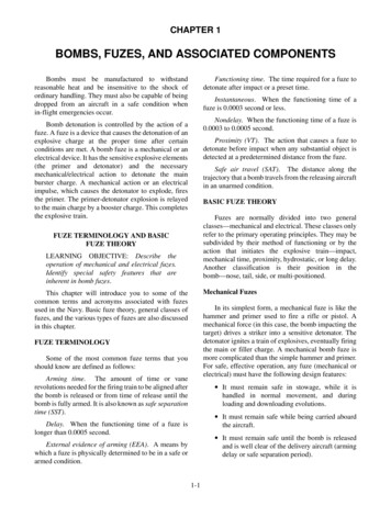
described in the preceding paragraph except that anoption wire is installed. If the pilot selects the primarymode of delivery when the weapon is released from theaircraft, only the arming wire is pulled out and theprimary mode of the fuze is initiated. If the pilot selectsthe option mode of delivery, both the arming wire andthe option wire are pulled out, initiating the option timemode of the fuze. If only the option time wire is pulledout on airborne release, the fuze will dud. Both the fuzearming wire and option wire must be pulled out for thefuze to function in the option mode.What bomb is used with the Mk 339mechanical time fuze?Q2.The primary and option delay of the Mk 339fuze is set at the factory. What means can beused to change the settings for tacticalrequirements?How can you tell if the Mk 339 fuze hasshifted from the primary to the option delay?Q4.Describe what you will see in the observationwindow of a Mk 339 fuze for the conditionslisted below:SafeArmedADAPTER BOOSTERSAn adapter booster is needed to install mechanicalfuzes in the Mk 80 (series) general-purpose bombs. Theadapter boosters currently in use are the M148/T45E,M148E1 (nose), and the M150/T46 (tail).REVIEW NUMBER 3Q1.Q3.M148/M148E1/T45 (Series) Adapter BoosterThe M148/M148E1/T45 (series) adapter booster(fig. 1-4) permits the use of mechanical nose fuzes inFigure 1-4.—Adapter-booster M148/E1 (series).1-8
REVIEW NUMBER 3 ANSWERSthe Mk 80 (series) bombs. The adapter booster isexternally threaded for installation in the bomb fuzewell and internally threaded for installation of the fuze.The casing contains the booster charge that is threadedonto the base of the adapter.The M148E1 adapter booster is similar in externalappearance to the earlier M148/T45 (series). Thedifferences are the nomenclature marking on the face ofthe adapter booster collar, the words THERMALLYPROTECTED in bold black letters, and a yellow bandaround the adapter booster casing, which indicates thatit is loaded with explosives. The M148E1 wasdeveloped for use with thermally protected bombs.A1.The Mk 20 is used with the Mk 339mechanical time fuze.A2.The primary and option delays can bechanged by adjusting the primary and optiontime-setting dials.A3.You can tell if the fuze has shifted from theprimary to the option delay by checking thetime setting observation window of the fuze.A4.Safe—Green foil is intact.Armed—Green foil is pierced by the indicatorpin.Adapter booster M150/T46 (Series)The M150/T46 (series) adapter boosters consist oftwo separate explosive components. The primaryadapter booster receives a 2.0-inch diameter fuze. TheT46 (series) contains a fuze adapter sleeve for use withthe 1.5-inch diameter fuze. A hole is drilled through thethreads of the primary adapter booster for insertion of aThe adapter booster M150/T46 (series) (fig. 1-5)permits the use of mechanical tail fuzes with Mk 80(series) bombs. The M150/T46 adapter boosters differonly in internal construction, and they may be usedinterchangeably.Figure 1-5.—Adapter-booster M150/T46 (series).1-9
DESCRIPTIONlocking pin for use with the long-delay fuze. This pinlocks the adapter booster to the base plug of the bomband prevents removal of the adapter booster while thefuze is installed. The M150 has a yellow band aroundthe adapter booster casing, which indicates that it isloaded with explosives.The Mk 376 Mod 0 electric tail fuze is detonatorsafe. The booster contain 4.3 ounces of tetryl explosive.This fuze is classified HERO SAFE, and no unusualRADHAZ precautions are required under normaloperating conditions.Four discreet dc voltages for in-flight selection offunctioning delay times are used in the Mk 376 fuze.The Mk 31 safety device automatically selects armingdelay times.ELECTRICAL FUZESLEARNING OBJECTIVE: Identify thevarious types of electrical fuzes to include theirphysical description and functional operation.MK 31 SAFETY DEVICEThe Mk 376 (fig. 1-6) electric bomb fuze providesan all-electric capability for the Mk 80 (series) bombswith either conical or retarding fins, thermallyprotected bombs, and laser-guided bombs (LGB).Electric fuzes require an electric pulse from the aircraftfuze function control (FFC) system. The FFC givesin-flight selection of function delay and arming delaytimes. The 376 fuze is used with the Mk 43target-detecting device for airburst capability.The Mk 31 safety device is used to adapt the fuze tothe fuze well of the bomb, provide mechanical safing ofthe fuze, and unlock the timer-decelerometer. Thesafety device contains a pop-out pin that locks the fuzein an unarmed condition. The spring-loaded pin is heldin the safe position by either a safety cotter pin or anarming wire. When the weapon is released from theaircraft, the arming wire is pulled from the pop-out pin,allowing the pin to pop out, unlock the decelerometer,thus initiating the arming time. When the free-fall modeof delivery is used the Mk 376 fuze, arming iscompleted 10.0 seconds after release from the aircraft.If the Mk 31 safety device senses weapon deceleration(Snakeye fins open), the internal circuits of the fuze areswitched, and the fuze becomes armed in 2.6 seconds.The quicker arming time is required to ensure the fuzeis fully armed for low-altitude delivery. If decelerationis not sensed by 2.6 seconds, the fuze arming delaycontinues to the 10.0-second arming time.FUNCTIONAL OPERATIONThe following description applies specifically tothe Mk 376 fuze.Two arming delays are used in the Mk 376fuze—2.6 seconds for retarded delivery and 10.0seconds for unretarded delivery. The appropriatearming delay is automatically selected by the fuzeaccording to the actual delivery mode of the weapon.That is, if the weapon does not retard, whetherintentionally or unintentionally, the fuze automaticallyprovides a 10.0-second arming delay.At release, the arming wire is withdrawn and acharging voltage ( 300, 195, -195, or -300 Vdc) isapplied to the fuze. The pilot selects the voltage in flightby the fuze function control set located in the cockpit.The fuze polarity and level of the fuze charging voltageis important only with respect to functioning delay.Figure 1-6.—Mk 376 Mod 0 electric fuze.1-10
5.5, and 10.0 seconds) and four functioning delaysettings (10, 25, and 60 milliseconds, andinstantaneous). Only 2.6/60, 2.6/25, 2.6/10, and2.6/inst high drag arm/delay switch positions areauthorized for Navy/Marine Corps use. The low dragarm time switch should always be in the X position. Thelow drag arm time rotary switch is positioned at X forshipping, storage, and all FFCS (fuze function controlset) use. The FMU-139 fuze differs from the Mk 376fuze in that the gag rod and arming wire housing arelocated in the center of the faceplate (fig. 1-9).Arming is the same in any case. A regulator in the fuzeconverts the applied voltage to the required level andpolarity. It is then applied to the energy storage unit andthe 2.6-second timer. If the weapon decelerates, the Mk31 safety device senses the deceleration and causes theretard switch to close. At 2.6 seconds, the timercompletes its cycle and transfers the voltage to therotor-actuating bellows. The bellows operate and turnthe rotor to the armed position.If the weapon does not decelerate, the retard switchdoes not close. The 2.6-second timer continues to run.At 3.8 seconds, the Mk 31 safety device causes thevoltage to transfer to the input of the rotor-actuatingbellows. At 10.0 seconds, the bellows operates andturns the rotor to the armed position.ARMING SAFETY SWITCH MK 122 MOD 0The Mk 122 Mod 0 arming safety switch (fig. 1-10)connects the fuze control circuits of the bomb in theaircraft to the electric fuze circuits in the bomb. Thisswitch provides an open circuit and a RADHAZ shieldto prevent electromagnetic radiation from entering thefuze circuits.FMU-152/B ELECTRONIC BOMB FUZEThe FMU-152/B is an advanced fuze system foruse in general purpose and penetrating unitarywarheads. The FMU-152/B provides safing, in-flightcockpit selection, and multifunction and multiple delayarming and fuzing functions. The FMU-152/B is amultifunction; multiple delay fuze system withhardened target capabilities that provide arming andfuzing functions for general purpose and penetrating,unitary warheads. The FMU-152/B system operates inthree fuze mission phases: the “pre-release,” “pre-arm,”and “post-arm” phases. The “pre-release” phaseincludes all fuze functions performed prior to the pointat which the weapon is released from the deliveryaircraft. The “pre-arm” phase includes all fuzefunctions occurring between weapon release andweapon arming. The “post-arm” phase includes all fuzefunctions after the weapon is armed.While the weapon is loaded, the coaxial cable ofthe switch is plugged into the receptacle of the aircraft'selectrical arming unit. When the bomb is suspendedfrom the rack, the lanyard is attached to a fixture on therack or pylon. Upon bomb release, the lanyard pulls thelanyard pin and closes the fuze circuit. The lanyard islong enough so the weapon separates from the bombrack suspension hooks before the lanyard pin is pulledfrom the switch. This ensures that the fuze does notreceive charging voltages in case of weapon releasefailure. The coaxial cable is longer than the lanyard,which permits sufficient time for the charging voltageto pass from the electrical arming unit on the aircraft tothe fuze electric circuits on the bomb before the cable ispulled free or breaks from the arming unit receptacle.NOTE: The Mk 122 Mod 0 switch must beinstalled and removed in a RADHAZ-freeenvironment.FMU-143E/B ELECTRIC TAIL FUZEThe FMU-143E/B fuze (fig. 1-7) is used with theGBU-24B/B. It is initiated by the FZU-32B/B initiator,which is used to generate and supply power to arm thefuze. The safe condition is verified by the presence of asafety pin or arming wire through the pop-out pin (gagrod).MK 43 MOD 0 TARGET DETECTING DEVICEThe Mk 43 Mod 0 target-detecting device (fig.1-11) is a proximity nose element that gives airburstcapability for electric-fuzed Mk 80 (series) bombs.FMU-139 (SERIES) ELECTRONIC BOMB FUZEThe Mk 43 Mod 0 element is compatible with allelectric tail fuzes and is identified by the dark greencolor of the nose cone. A thermal battery powers itsinternal circuitry. The thermal battery is initiated by 300 volts dc or by the striker rod.The FMU-139 (series) electronic bomb fuze (fig.1-8) is an electronic impact or impact-delay fuze. It isused in Mk 80 series general-purpose bombs, includinglaser-guided bombs. The arming times are in-flightselectable, and the functioning delay must be set duringweapon assembly. There are three arming times (2.6,The Mk 43 is initiated mechanically (striker rod)only when a delay airburst is desired. This is the1-11
Figure 1-7.—FMU-143E/B electric tail fuze.1-12
Figure 1-8.—FMU-139 (series) electronic bomb fuze.1-13
Figure 1-9.—FMU-139 (series) electronic bomb fuze gag rod in safe and unsafe positions.1-14
Figure 1-10.—Mk 122 Mod 0 arming safety switch.Figure 1-11.—Mk 43 Mod 0 target detecting device.1-15
When the Mk 43 is initiated by the conventionalmethod, fuze functioning occurs instantaneously whena firing pulse is received from the thermal battery. If thealternate method is used (striker rod), the fuze is set foreither of the two functioning delays. Detonation of thebomb is delayed by either 0.015 second or 0.100second, depending on the delay that is selected.alternate method used to provide operation when thefuze is not initiated with the 300 volts dc. Theconventional mode is selected by initiating the fuzewith 300 volts dc. When the fuze is initiated with 300 volts dc, the Mk 43
general-purpose (LDGP) bombs. The M904 (series) fuze is installed in the nose fuze well of the bomb and requires the use of an adapter booster. The fuze is detonator-safe, and it contains two .