Transcription
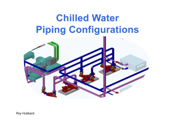
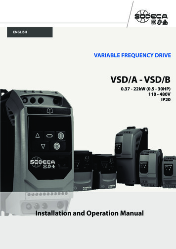
ENGLISHVARIABLE FREQUENCY DRIVETroubleshootingVSD/A - VSD/B0.37 - 22kW (0.5 - 30HP)110 - 480VIP201234567Installation and Operation Manual8910www.invertekdrives.comVersion 1.01 Optidrive ODE-3 User Guide 1
1. Quick Start Up. . . . . . . . . . . . . . . . . . . . . . . . . . . . . . . . . 41.1. Important Safety Information. . . . . . . . . . . . . . . . . . . . . . . . . . . . 41.2. Quick Start Process. . . . . . . . . . . . . . . . . . . . . . . . . . . . . . . . . . . . 51.3. Installation Following a Period of Storage. . . . . . . . . . . . . . . . . 62. General Information and Ratings. . . . . . . . . . . . . . . . . 72.1. Identifying the Drive by Model Number. . . . . . . . . . . . . . . . . . . 72.2. Drive Model Numbers. . . . . . . . . . . . . . . . . . . . . . . . . . . . . . . . . 73. Mechanical Installation . . . . . . . . . . . . . . . . . . . . . . . . . 83.1. General . . . . . . . . . . . . . . . . . . . . . . . . . . . . . . . . . . . . . . . . . . . . . 83.2. UL Compliant Installation. . . . . . . . . . . . . . . . . . . . . . . . . . . . . . . 83.3. Mechanical Dimensions and Mounting – IP20 Open Units. . . 83.4. Guidelines for Enclosure Mounting . . . . . . . . . . . . . . . . . . . . . . 94. Power & Control Wiring. . . . . . . . . . . . . . . . . . . . . . . . 104.1. Connection Diagram. . . . . . . . . . . . . . . . . . . . . . . . . . . . . . . . . . 104.2. Protective Earth (PE) Connection. . . . . . . . . . . . . . . . . . . . . . . . 104.3. Incoming Power Connection. . . . . . . . . . . . . . . . . . . . . . . . . . . 114.4. Motor Connection. . . . . . . . . . . . . . . . . . . . . . . . . . . . . . . . . . . 124.5. Motor Terminal Box Connections. . . . . . . . . . . . . . . . . . . . . . . 124.6. Control Terminal Wiring. . . . . . . . . . . . . . . . . . . . . . . . . . . . . . . 124.7. Control Terminal Connections . . . . . . . . . . . . . . . . . . . . . . . . . . 134.8. Motor Thermal Overload Protection. . . . . . . . . . . . . . . . . . . . . 134.9. EMC Compliant Installation. . . . . . . . . . . . . . . . . . . . . . . . . . . . 144.10. Optional Brake Resistor . . . . . . . . . . . . . . . . . . . . . . . . . . . . . . 155. Operation . . . . . . . . . . . . . . . . . . . . . . . . . . . . . . . . . . . 165.1. Managing the Keypad. . . . . . . . . . . . . . . . . . . . . . . . . . . . . . . . 165.2. Operating Displays. . . . . . . . . . . . . . . . . . . . . . . . . . . . . . . . . . . 165.3. Changing Parameters. . . . . . . . . . . . . . . . . . . . . . . . . . . . . . . . . 165.4. Read Only Parameter Access. . . . . . . . . . . . . . . . . . . . . . . . . . 175.5. Resetting Parameters. . . . . . . . . . . . . . . . . . . . . . . . . . . . . . . . . . 175.6. Resetting a Fault. . . . . . . . . . . . . . . . . . . . . . . . . . . . . . . . . . . . . . 175.7. LED Display . . . . . . . . . . . . . . . . . . . . . . . . . . . . . . . . . . . . . . . . . 1726. Parameters . . . . . . . . . . . . . . . . . . . . . . . . . . . . . . . . 186.1. Standard Parameters. . . . . . . . . . . . . . . . . . . . . . . . . . . . . . . . 186.2. Extended Parameters. . . . . . . . . . . . . . . . . . . . . . . . . . . . . . . 206.3. Advanced Parameters . . . . . . . . . . . . . . . . . . . . . . . . . . . . . . 256.4. P-00 Read Only Status Parameters. . . . . . . . . . . . . . . . . . . . 277. Analog and Digital Input Macro Configurations. . . 287.1. Overview . . . . . . . . . . . . . . . . . . . . . . . . . . . . . . . . . . . . . . . . . 287.2. Example Connection Diagrams. . . . . . . . . . . . . . . . . . . . . 287.3. Macro Functions Guide Key. . . . . . . . . . . . . . . . . . . . . . . . 297.4. Macro Functions – Terminal Mode (P-12 0) . . . . . . . . 30 7.5. Macro Functions - Keypad Mode (P-12 1 or 2). . . . . . 31 7.6. Macro Functions - Fieldbus Control Mode (P-12 3, 4, 7, 8or 9). . . . . . . . . . . . . . . . . . . . . . . . . . . . . . . . . . . . . . . . . . . . . . . . . 317.7. Macro Functions - User PI Control Mode (P-12 5 or 6). . . 337.8. Fire Mode . . . . . . . . . . . . . . . . . . . . . . . . . . . . . . . . . . . . . . . . 328. Modbus RTU Communications. . . . . . . . . . . . . . . . . 338.1. Introduction. . . . . . . . . . . . . . . . . . . . . . . . . . . . . . . . . . . . . . . . 338.2. Modbus RTU Specification. . . . . . . . . . . . . . . . . . . . . . . . . . 338.3. RJ45 Connector Configuration. . . . . . . . . . . . . . . . . . . . . . . 338.4. Modbus Register Map. . . . . . . . . . . . . . . . . . . . . . . . . . . . . . 339. Technical Data. . . . . . . . . . . . . . . . . . . . . . . . . . . . . . 369.1. Environmental. . . . . . . . . . . . . . . . . . . . . . . . . . . . . . . . . . . . . . 369.2. Rating Tables. . . . . . . . . . . . . . . . . . . . . . . . . . . . . . . . . . . . . . 369.3. Single Phase Operation of Three Phase Drives. . . . . . . . . . 379.4. Additional Information for UL Compliance. . . . . . . . . . . . . . 379.5. EMC Filter Disconnect. . . . . . . . . . . . . . . . . . . . . . . . . . . . . . 3810. Troubleshooting . . . . . . . . . . . . . . . . . . . . . . . . . . . 3910.1. Fault Code Messages. . . . . . . . . . . . . . . . . . . . . . . . . . . . . . 3911. VSD Watts Loss According to IEC61800-9-2. . . . . . . . . . 4011.1. IP20 Units. . . . . . . . . . . . . . . . . . . . . . . . . . . . . . . . . . . . . . . . 40
ENGLISHDeclaration of Conformity:SODECA hereby states that the VSD/A and VSD/B product range conforms to the relevant safety provisions of the followingcouncil directives:2014/30/EU (EMC) and 2014/35/EU (LVD)Design and manufacture in accordance with the following harmonised European standards:EN 61800-5-1: 2003 Adjustable speed electrical power drive systems. Safety requirements. Electrical, thermal and energy.EN 61800-3 2nd Ed: 2004 Adjustable speed electrical power drive systems. EMC requirements and specific test methodsEN61000-3-12 Limits for harmonic currents produced by equipment connected to public low-voltage systems with inputcurrent 16 A and 75 A per phase. Requirements are fulfilled without the need for Line Reactors according to the THCvalues specified in Table 3 for values of RSCE 185 for all units intended for operation on 400 Volt, 3 Phase Supply.EN 55011: 2007 Limits and Methods of measurement of radio disturbance characteristics of industrial, scientific and medical(ISM) radio-frequency equipment (EMC)EN60529 : 1992 Specifications for degrees of protection provided by enclosuresElectromagnetic CompatibilityAll VSD/A-RFT are designed with high standards of EMC in mind. All versions intended for use within the European Unionare fitted with an internal EMC filter. This EMC filter is designed to reduce the conducted emissions back into the supply viathe power cables for compliance with harmonised European standards.It is the responsibility of the installer to ensure that the equipment or system into which the product is incorporatedcomplies with the EMC legislation of the country of use. Within the European Union, equipment into which this productis incorporated must comply with the EMC Directive 2014/30/EU. This User Guide provides guidance to ensure that theapplicable standards may be achieved:Copyright SODECA All rights reserved. No part of this User Guide may be reproduced or transmitted in any form or by any means, electricalor mechanical including photocopying, recording or by any information storage or retrieval system without permission inwriting from the publisher.All Sodeca VSD units carry a 2 year warranty against manufacturing defects from the date of manufacture. The manufactureraccepts no liability for any damage caused during or resulting from transport, receipt of delivery, installation orcommissioning. The manufacturer also accepts no liability for damage or consequences resulting from inappropriate,negligent or incorrect installation, incorrect adjustment of the operating parameters of the drive, incorrect matching of thedrive to the motor, incorrect installation, unacceptable dust, moisture, corrosive substances, excessive vibration or ambienttemperatures outside of the design specification.The local distributor may offer different terms and conditions at their discretion, and in all cases concerning warranty, thelocal distributor should be contacted first.This user guide is the “original instructions” document. All non-English versions are translations of the “original instructions”.Contents of this User Guide are believed to be correct at the time of printing. In the interest of a commitment to a policy ofcontinuous improvement, the manufacturer reserves the right to change the specification of the product or its performanceor the contents of the User Guide without notice.The contents of this User Guide are believed to be correct at the time of printing. In the interest of a commitment to apolicy of continuous improvement, the manufacturer reserves the right to change the specification of the product or itsperformance or the contents of the User Guide without notice.This User Guide is for use with version 2.50 Firmware. The firmware version can be viewed in parameter P0-28.User Guide Revision 3.09SODECA adopts a policy of continuous improvement and whilst every effort has been made to provide accurate and up todate information, the information contained in this User Guide should be used for guidance purposes only and does notform the part of any contract.3
1. Quick Start Up1.1. Important Safety InformationPlease read the IMPORTANT SAFETY INFORMATION below, and all Warning and Caution information elsewhere.Danger: Indicates a risk of electric shock, which,Danger: Indicates a potentially hazardous situationif not avoided, could result in damage to theother than electrical, which if not avoided, couldequipment and possible injury or death.result in damage to property.This variable speed drive product (VSD) is intended forWithin the European Union, all machinery in which this product isprofessional incorporation into complete equipment or systems asused must comply with Directive 2006/42/EC, Safety of Machinery.part of a fixed installation. If installed incorrectly it may present aIn particular, the machine manufacturer is responsible for providingsafety hazard. The VSD uses high voltages and currents, carriesa main switch and ensuring the electrical equipment complies witha high level of stored electrical energy, and is used to controlEN60204-1.mechanical plant that may cause injury. Close attention is requiredThe level of integrity offered by the VSD control input functions – forto system design and electrical installation to avoid hazards inexample stop/start, forward/reverse and maximum speed is noteither normal operation or in the event of equipment malfunction.sufficient for use in safety-critical applications without independentOnly qualified electricians are allowed to install and maintain thischannels of protection. All applications where malfunction couldproduct.cause injury or loss of life must be subject to a risk assessment andSystem design, installation, commissioning and maintenance mustfurther protection provided where needed.be carried out only by personnel who have the necessary trainingThe driven motor can start at power up if the enable input signal isand experience. They must carefully read this safety informationpresent.and the instructions in this Guide and follow all informationThe STOP function does not remove potentially lethal highregarding transport, storage, installation and use of the VSD,voltages. ISOLATE the drive and wait 10 minutes before startingincluding the specified environmental limitations.any work on it. Never carry out any work on the Drive, Motor orDo not perform any flash test or voltage withstand test on the VSD.Motor cable whilst the input power is still applied.Any electrical measurements required should be carried out withThe VSD can be programmed to operate the driven motor atthe VSD disconnected.speeds above or below the speed achieved when connecting theElectric shock hazard! Disconnect and ISOLATE the VSDmotor directly to the mains supply. Obtain confirmation from thebefore attempting any work on it. High voltages are presentmanufacturers of the motor and the driven machine about suitabilityat the terminals and within the drive for up to 10 minutes afterfor operation over the intended speed range prior to machine startdisconnection of the electrical supply. Always ensure by using aup.suitable multimeter that no voltage is present on any drive powerDo not activate the automatic fault reset function on any systemsterminals prior to commencing any work.whereby this may cause a potentially dangerous situation.Where supply to the drive is through a plug and socket connector,VSDs are intended for indoor use only.do not disconnect until 10 minutes have elapsed after turning offWhen mounting the drive, ensure that sufficient cooling is provided.the supply.Do not carry out drilling operations with the drive in place, dust andEnsure correct earthing connections. The earth cable must beswarf from drilling may lead to damage.sufficient to carry the maximum supply fault current which normallyThe entry of conductive or flammable foreign bodies should bewill be limited by the fuses or MCB. Suitably rated fuses or MCBprevented. Flammable material should not be placed close to theshould be fitted in the mains supply to the drive, according to anydrivelocal legislation or codes.Relative humidity must be less than 95% (non-condensing).Ensure correct earthing connections and cable selection as perdefined by local legislation or codes. The drive may have aEnsure that the supply voltage, frequency and no. of phases (1 orleakage current of greater than 3.5mA; furthermore the earth3 phase) correspond to the rating of the VSD as delivered.cable must be sufficient to carry the maximum supply fault currentNever connect the mains power supply to the Output terminals U,which normally will be limited by the fuses or MCB. Suitably ratedV, W.fuses or MCB should be fitted in the mains supply to the drive,Do not install any type of automatic switchgear between the driveaccording to any local legislation or codes.and the motor.Do not carry out any work on the drive control cables whilst powerWherever control cabling is close to power cabling, maintainis applied to the drive or to the external control circuits.a minimum separation of 100 mm and arrange crossings at 90degrees. Ensure that all terminals are tightened to the appropriatetorque setting.Do not attempt to carry out any repair of the VSD. In the case ofsuspected fault or malfunction, contact your local SODECA SalesPartner for further assistance.4
ENGLISH1.2. Quick Start ProcessStepAction1 Identify the Enclosure Type, Model Type and ratings ofyour drive from the model code on the label. In particular- Check the voltage rating suits the incoming supply- Check the output current capacity meets or exceeds thefull load current for the intended motor2 Unpack and check the drive. Notify the supplier andshipper immediately of any damage.3 Ensure correct ambient and environmental conditions forthe drive are met by the proposed mounting location.4 Install the drive in a suitable cabinet (IP20 Units) ensuringsuitable cooling air is available.56789101112131415Select the correct power and motor cables accordingto local wiring regulations or code, noting the maximumpermissible sizesIf the supply type is IT or corner grounded, disconnect theEMC filter before connecting the supply.Check the supply cable and motor cable for faults or shortcircuits.Route the cables.Check that the intended motor is suitable for use, notingany precautions recommended by the supplier ormanufacturer.Check the motor terminal box for correct Star or Deltaconfiguration where applicable.Ensure wiring protection is providing, by installing asuitable circuit breaker or fuses in the incoming supply line.See section2.1. Identifying the Drive by Model NumberPage79.1. Environmental363.1. General3.3. Mechanical Dimensions and Mounting – IP20Open Units3.4. Guidelines for Enclosure Mounting889.2. Rating Tables9369.5. EMC Filter Disconnect384.9. EMC Compliant Installation144.5. Motor Terminal Box Connections124.3.2. Fuse / Circuit Breaker Selection9.2. Rating TablesConnect the power cables, especially ensuring the4.1. Connection Diagramprotective earth connection is made.4.2. Protective Earth (PE) Connection4.3. Incoming Power Connection4.4. Motor ConnectionConnect the control cables as required for the application. 4.6. Control Terminal Wiring4.9. EMC Compliant Installation7. Analog and Digital Input Macro Configurations7.2. Example Connection DiagramsThoroughly check the installation and wiring.Commission the drive parameters.5.1. Managing the Keypad6. Parameters1136101011121214282816185
1.3. Installation Following a Period of Storage100%Where the drive has been stored for some time prior to installation,or has remained without the main power supply present for anextended period of time, it is necessary to reform the DC capacitorswithin the drive according to the following table before operation.For drives which have not been connected to the main power supplyfor a period of more than 2 years, this requires a reduced mainsvoltage mains voltage to be applied for a time period, and graduallyincreased prior to operating the drive. The voltage levels relative tothe drive rated voltage, and the time periods for which they must beapplied are shown in the following table. Following completion of theprocedure, the drive may be operated as normal.75%50%25%T1Storage Period/Power-OFFPeriodInitialInputVoltageLevelUp to 1 Year100%1 – 2 Years100%1 Hour2 – 3 Years25%30 Minutes50%30 MinutesMore than 3 Years25%2 Hours50%2 HoursTimePeriod T3T4TimePeriod T3FinalInputVoltageLevelTimePeriod T475%30 Minutes100%30 Minutes75%2 Hours100%2 HoursN/AN/A1.4. Quick Start OverviewQuick Start – IP20- Connect a Start / Stop switch between control terminals 1 &2o Close the Switch to Starto Open to Stop- Connect a potentiometer (5k – 10kΩ) between terminals 5, 6and 7 as shown o Adjust the potentiometer to vary the speed from P-02(0Hz default) to P-01 (50 / 60 Hz default)6TimePeriod T2T2
ENGLISH2. General Information and Ratings2.1. Identifying the Drive by Model NumberEach drive can be identified by its model number, as shown in the table below. The model number is on the shipping label and the drivenameplate. The model number includes the drive and any options.VSD*/A-RFM-0.5-IP20NameMotor type and inverter incoming supply voltagePowerProtection1/A3/AThree-phase asynchronous motors. 230V single phase powerThree-phase asynchronous motors. 400 V three-phase powerHpIP20115RFMRFT230V Three-phase asynchronous motors. 115V Single-phase incoming supply.230V Three-phase asynchronous motors. 230V Single-phase incoming supply.400V Three-phase asynchronous motors. 400V Three-phase incoming supply.VSD*/B-0.75-IP20NameMotor type and inverter incoming supply voltagePowerProtection1/B3/BThree-phase synchronous motors. 230V single phase powerThree-phase synchronous motors. 400 V three-phase powerkWIP202.2. Drive Model NumbersPower (Hp)Output current (A)SizeIP20 111518.5222,34,3710,52,24,15,89,51418243039467
3. Mechanical Installation3.1. General- The VSD should be mounted in a vertical position only, on a flat, flame resistant, vibration free mounting using the integral mounting holesor DIN Rail clip (Frame Sizes 1 and 2 only).- IP20 VSDs are designed to be installed in suitable enclosures to protect them from the environment.- Do not mount flammable material close to the VSD.- Ensure that the ambient temperature range does not exceed the permissible limits for the VSD given in section 9.1. Environmental.- Provide suitable clean, moisture and contaminant free cooling air sufficient to fulfil the cooling requirements of the VSD.3.2. UL Compliant InstallationRefer to section 9.4. Additional Information for UL Compliance on page 37 for Additional Information for UL Compliance.3.3. Mechanical Dimensions and Mounting – IP20 Open 9.9Mounting BoltsFrame Size1-3458DL2/N L34 x M5 (#8)4 x M84 x M8Tightening TorquesFrame SizeControl TerminalsPower Terminals1-3450.5 Nm (4.4 lb-in)0.5 Nm (4.4 lb-in)0.5 Nm (4.4 lb-in)1 Nm (9 lb-in)2 Nm (18 lb-in)4 Nm (35.5 lb-in)
ENGLISH3.4. Guidelines for Enclosure Mounting- IP20 drives are are designed to be installed in suitable enclosures to protect them from the environment.- Enclosures should be made from a thermally conductive material.- Ensure the minimum air gap clearances around the drive as shown below are observed when mounting the drive.- Where ventilated enclosures are used, there should be venting above the drive and below the drive to ensure good air circulation. Airshould be drawn in below the drive and expelled above the drive.- In any environments where the conditions require it, the enclosure must be designed to protect the VSD against ingress of airborne dust,corrosive gases or liquids, conductive contaminants (such as condensation, carbon dust, and metallic particles) and sprays or splashingwater from all directions.- High moisture, salt or chemical content environments should use a suitably sealed (non-vented) enclosure.- The enclosure design and layout should ensure that the adequate ventilation paths and clearances are left to allow air to circulatethrough the drive heatsink. SODECA recommend the following minimum sizes for drives mounted in non-ventilated metallic enclosures:Drive Size12345NOTEXAbove & BelowYEither SideZBetweenRecommendedairflowmminmminmminCFM 76112260120104Dimension Z assumes that the drives are mounted side-by-side with no clearance.Typical drive heat losses are 3% of operating load conditions.Above are guidelines only and the operating ambient temperature of the drive MUST bemaintained at all times.9
4. Power & Control Wiring4.1. Connection DiagramMABCDEFGHIJLMKeyProtective Earth (PE) ConnectionIncoming Power ConnectionFuse / Circuit Breaker SelectionOptional Input ChokeOptional External EMC FilterInternal Disconnect / IsolatorOptional Brake ResistorMotor ConnectionAnalog OutputAuxiliary Relay OutputAnalog InputsDigital 511154.7.14.7.24.7.34.7.4131313134.2. Protective Earth (PE) ConnectionGrounding GuidelinesThe ground terminal of each VSD should be individually connected DIRECTLY to the site ground bus bar (through the filter if installed). VSDground connections should not loop from one drive to another, or to, or from any other equipment. Ground loop impedance must confirmto local industrial safety regulations. To meet UL regulations, UL approved ring crimp terminals should be used for all ground wiringconnections.The drive Safety Ground must be connected to system ground. Ground impedance must conform to the requirements of national and localindustrial safety regulations and/or electrical codes. The integrity of all ground connections should be checked periodically.Protective Earth ConductorThe Cross sectional area of the PE Conductor must be at least equal to that of the incoming supply conductor.Safety GroundThis is the safety ground for the drive that is required by code. One of these points must be connected to adjacent building steel (girder, joist), afloor ground rod, or bus bar. Grounding points must comply with national and local industrial safety regulations and/or electrical codes.Motor GroundThe motor ground must be connected to one of the ground terminals on the drive.10
ENGLISHGround Fault MonitoringAs with all inverters, a leakage current to earth can exist. The VSD is designed to produce the minimum possible leakage currentwhilst complying with worldwide standards. The level of current is affected by motor cable length and type, the effective switchingfrequency, the earth connections used and the type of RFI filter installed. If an ELCB (Earth Leakage Circuit Breaker) is to be used, thefollowing conditions apply:- A Type B Device must be used.- The device must be suitable for protecting equipment with a DC component in the leakage current.- Individual ELCBs should be used for each VSD.Shield Termination (Cable Screen)The safety ground terminal provides a grounding point for the motor cable shield. The motor cable shield connected to this terminal(drive end) should also be connected to the motor frame (motor end). Use a shield terminating or EMI clamp to connect the shield tothe safety ground terminal.4.3. Incoming Power Connection4.3.1. Cable Selection- For 1 phase supply, the mains power cables should be connected to L1/L, L2/N.- For 3 phase supplies, the mains power cables should be connected to L1, L2, and L3. Phase sequence is not important.- For compliance with CE and C Tick EMC requirements, refer to section 4.9. EMC Compliant Installation on page 14.- A fixed installation is required according to IEC61800-5-1 with a suitable disconnecting device installed between the VSD and theAC Power Source. The disconnecting device must conform to the local safety code / regulations (e.g. within Europe, EN60204-1,Safety of machinery).- The cables should be dimensioned according to any local codes or regulations. Maximum dimensions are given in section 9.2.Rating Tables.4.3.2. Fuse / Circuit Breaker Selection- Suitable fuses to provide wiring protection of the input power cable should be installed in the incoming supply line, according tothe data in section 9.2. Rating Tables. The fuses must comply with any local codes or regulations in place. In general, type gG (IEC60269) or UL type J fuses are suitable; however in some cases type aR fuses may be required. The operating time of the fuses must bebelow 0.5 seconds.- Where allowed by local regulations, suitably dimensioned type B MCB circuit breakers of equivalent rating may be utilised in placeof fuses, providing that the clearing capacity is sufficient for the installation.- The maximum permissible short circuit current at the VSD Power terminals as defined in IEC60439-1 is 100kA.4.3.3. Optional Input Choke- An optional Input Choke is recommended to be installed in the supply line for drives where any of the following conditions occur:o The incoming supply impedance is low or the fault level / short circuit current is high.o The supply is prone to dips or brown outs.o An imbalance exists on the supply (3 phase drives).o The power supply to the drive is via a busbar and brush gear system (typically overhead Cranes).- In all other installations, an input choke is recommended to ensure protection of the drive against power supply faults. Part numbersare shown in the table.Supply230 Volt1 Phase400 Volt3 PhaseFrame SizeAC Input -20OPT-2-L3090-2011
4.4. Motor Connection- The drive inherently produces fast switching of the output voltage (PWM) to the motor compared to the mains supply, for motors whichhave been wound for operation with a variable speed drive then there is no preventative measures required, however if the quality ofinsulation is unknown then the motor manufacturer should be consulted and preventative measures may be required.- The motor should be connected to the VSD U, V, and W terminals using a suitable 3 or 4 core cable. Where a 3 core cable is utilised,with the shield operating as an earth conductor, the shield must have a cross sectional area at least equal to the phase conductors whenthey are made from the same material. Where a 4 core cable is utilised, the earth conductor must be of at least equal cross sectional areaand manufactured from the same material as the phase conductors.- The motor earth must be connected to one of the VSD earth terminals.- Maximum permitted motor cable length for all models: 100 metres shielded, 150 metres unshielded.- Where multiple motors are connected to a single drive using parallel cables, an output choke must be installed.4.5. Motor Terminal Box ConnectionsMost general purpose motors are wound for operation on dual voltage supplies. This is indicated on the nameplate of the motor. Thisoperational voltage is normally selected when installing the motor by selecting either STAR or DELTA connection. STAR always gives thehigher of the two voltage ratings.Incoming Supply VoltageMotor Nameplate Voltages230230 / 400ConnectionDelta 400400 / 690400230 / 400StarÇ4.6. Control Terminal Wiring- All analog signal cables should be suitably shielded. Twisted pair cables are recommended.- Power and Control Signal cables should be routed separately where possible, and must not be routed parallel to each other.- Signal levels of different voltages e.g. 24 Volt DC and 110 Volt AC, should not be routed in the same cable.- Maximum control terminal tightening torque is 0.5Nm.- Control Cable entry conductor size: 0.05 – 2.5mm2 / 30 – 12 AWG.12
ENGLISH4.7. Control Terminal ConnectionsDefault ConnectionsControl TerminalSignalDescription 24Vdc user output, 100mA.1 24Vdc User Output2Digital Inpu
www.invertekdrives.com Version 1.01 Optidrive ODE-3 User Guide 1 1 2 3 4 5 6 7 8 9 10 Troubleshooting VSD/A - VSD/B 0.37 - 22kW (0.5 - 30HP) 110 - 480V IP20 .

