Transcription
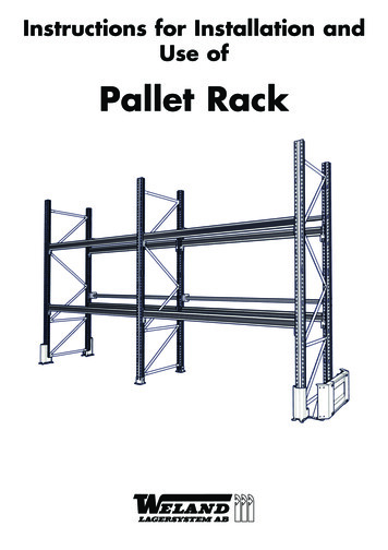
Instructions for Installation andUse ofPallet Rack
Prior to installation.Details about the building and the environment where the storage system will be used. Including the characteristics of the floor that will be used as the base for the storage equipment and the mechanical handling equipment.Details about the goods that will be stored in the equipment as well as specification of pallets or other types of load carrier. Specification of permitted loads on the storage equipment. Layout and design of equipment to enable the provision of sufficienthandling space for the safe loading in and out of goods for the intended use.Specification of the handling equipment that will be used, e.g. type of truck, together with storage equipment. Specified requirements for collision protection and capacity to withstand collisions. Specification of who will perform the installation of the storage equipment. Known information about future changes in storage needs.1. Place two posts on the ground, parallel witheach other. Check that the holes for attachingthe post foot are at the same end on both posts.2. Assemble the post foot on the post and fasten it in place using 1 M8 x 130 and lockingnut. The reinforcement plate, if any, is assembled from underneath, before the foot is put in place.3. The first horizontal strut is fastened in the 1sthole counting from the top (135 mm) on one ofthe posts. 1 M6 x 24 and locking nut.4. After this, the same horizontal strut, togetherwith the first diagonal strut, must be secured inthe 2nd hole down on the opposite post. 1 M6 x24 and locking nut.5. Then, set out the other diagonal and horizontal struts as shown in the bracing diagramon the next page or enclosed drawing. Use thenumber of M6 x 24 and locking nuts required.6. After this, erect a section consisting of 2 endpanels. Assemble the support beams from theinside, and push the lockplate firmly into place.(2 per support beam)8. All footplates must be anchored using 2M10 x 90 expander screws per footplate. Forinstallation on surfaces other than concrete,please contact WLS.9. Install each back stop bracket using 2 M8 x110. Push in the back beam and lock it on to thehooks in the brackets.7. After this, continue assembling the end panelsand support beams according to the previouspoints.2
AccessoriesEnd panel distanceAlternative post footWhen installing pallet racks back to back (doubleracks) at least two spacers must be used. The bottom one of these is placed adjoining the nextlowest horizontal strut. The upper end panel spacer is placed adjoining the upper diagonal strutbracket. At every fourth diagonalstrut bracket,there is an end panel spacer, unless there are twoor less diagonal struts to the upper end panel spacer.End panel spacers are used to keep the correct distance between the pallet racks and to provideincreased stability. Assemble using M8 x 120, washers and locking nuts.Post Protection/CollisionProtectionmm85Place the post protection above the footplate andsecure with 4 M10 x 90 expanders.Collision protection double endpanelEnd panel protection double. A middle supportmust be installed using M12 screw and nut.Anchor to the floor using 4 M10 x 90 expanders.Post protectionAssemble the post foot on the post and fasten itin place using 1 M6 x 35 and locking nut. Thereinforcement plate, if any, is assembled fromunderneath, before the foot is put in place.Collision protection single endpanelThe post protection must bepressed down(hammereddown) properly.It is easiest to install the post protection on theposts before the footplate (see point 2) but itcan be also installed from above later.Half-pallet insertPanel end single. Screw beam and feet togetherusing M12 screw and nut. After this, anchor to thefloor using 8 M10 x 90 expanders.Long-side insertM8 x 65Screw the half-pallet inserts together using 4M8 x 55 and locking nut per side.Attach the long-side inserts to the supportbeams using self-drilling screws.3
Load data/loading platesFor new installations, object specific loading diagrams are enclosed, see example below. The pallet rack configuration, such as distance between supportbeams, type of support beam etc., must not be larger than stated in the object specific or on general loading plates. The general loading data shown in thetables on page 5 is used in case of alterations or other changes to the pallet rack that differ from the original installation, where the purchaser doesn't find itnecessary to make use of the higher capacity provided by the object specific loading diagram.Loading plates must be placed where they are clearly visible. WLS provides fixings to fasten them to the pallet rack's panel ends.During alterations to the pallet rack, the load capacity may change. In connection with this, the supplier or an expert must be consulted and their recommendations followed. WLS provides object specific loading diagrams if requested by the purchaser in case of alterations or other changes to the pallet racks.Max. load per level (kg)h1Max. load per level (kg)Two support beams at the same height onebearing level.The greatest value for h1, h2 h3 etc. is hmax.,this is the design basis bearing level separation.h2Max. load per level (kg)The design basis is the lower value for the section loading or beam loading multiplied by thenumber of bearing levels.h3Max. section load(kg)Support beam length (mm)Bracing structure on endpanelsStrut lengthDepthHorizontal strut 1Diagonal strut 2Diagonal strut 3Diagonal strut 55006000
Load per sectionPost FLPost FHSection load (kg)Support beam typeSupport beam typeBearing levelhseparationSection load (kg)Bearing level separationhmax (mm)750h1000125015001750200022502500Support beam H120beam 5300hmax 085008000720067005900Post FMSection load(kg)Supportbeam typehmax 800128001010090008200Post FEHSection load (kg)Bearing level separationBhmax (mm)Support beam 00820069006300540050004700NOTE! It requires at least 2 bearing levels and support beam length 2700 mmNOTE! It requires at least 2 bearing levels and support beam length 2700 mmBBearing 125015001750200022502500Support beam 20beam typeH100H14012300 173001730010400 00173001690015000127001160010800NOTE! It requires at least 2 bearing levels and support beam length 2700 mmNOTE! It requires at least 2 bearing levels and support beam length 2700 mmLoad per levelBhhSupport beam typeSupportbeam typeSection load(kg)Bearing level 100H16084006400470039003300330029002600Support beam typeSupport beam typehh6500Support beam 50090009500100005
A few important points to check on the pallet rack before it is put intouse and thereafter daily inspection. Deviations must be remedied!The gradient relative to the vertical may be a maximum of H/350 (2.8 mm/m). For loaded racksH/350 H/200 (7.8 mm/m)1000 mmCrooked posts1000 mmSlopeAlong the support beams' length, the postsare permitted to deviate from the verticalby a maximum of 5 mm per metre.Along the pallet rack endpanel's depth, the postsare permitted to deviatefrom the vertical by amaximum of 3 mm permetre.Dents and foldsIf dents or folds appear on posts, struts or support beams,they must be replaced.Beams(remaining deformation of supportbeams)Sagging:Max. remaining sag after unloading from the maximum permitted load: L/1000.Sideways:Max. remaining bend after unloading from the maximumpermitted load: L/400.6End panelstrutLockplateMax.10 mmThe struts can be straightened ifthedeformation is less than 10 mm.Check the lockplates are in allsupport beams and that theyare pressed in completely.
InstallationCompetence and provision of installation instructions The installation must be performed in a professional manner according to Weland Lagersystem's installation instructionsin order to assure the quality of the installation because this has a major effect on the pallet rack's strength and function. Fitters assigned by Weland Lagersystem have the necessary experience and knowledge for the installation of pallet racks.If other personnel are assigned, they are assumed to have the equivalent competence to perform the installation based onthe installation instructions. Should personnel other than those assigned by Weland Lagersystem be used, the installation instructions provided must be followed exactly.Installation quality and strength Installation tolerances affect bearing capacity and mechanical strength and must comply with the requirements indicatedforadjustable pallet racks in SS-EN15620, unless otherwise stated by the designer.Important aspects to consider during installation The racks must be fastened to the floor according to the previous Instructions for Installation and Use If rear bracing is used (see separate installation instruction) the pallet rack's configuration must not be altered withoutcontacting WLS. The pallet rack's feet must be in contact with the floor or base/plinths over their entire area. Where necessary, use permanently placed steel levelling plates. Max. permitted difference in height for points 3 metres apart without levelling,depending on material handling equipment, is 4.0 mm. Instead of levelling plates, the entire surface of the footplate canbe cast in sufficiently strong and non-shrink concrete by an expert. Users should appoint an individual to be responsible for the storage equipment's safety and make this person's nameknown to the warehouse staff. The person in question must know about goods handling in the warehouse and its risks.This is best done by means of a risk analysis. Warehouse staff should be trained in using storage equipment and handling equipment.UseMeasurements to take into consideration during installation/use; see SSEN 15620:2008.ExplanationA free space for manoeuvringDp unit load or load pallet's depthD width for 90 turn for truck and loadAst minimum free aisle width between the load unit's front orthe rack position at all levelsWp the load unit and the load pallet's widthExplanation1 Pallet with load overhang2 Pallet without load overhang3 Beam shows no saggingHorizontal and vertical handling space for trucks in one section.Beam height Yh from floor up tobeam level, mm30006000900013000X3 X4 X5 X6mm757575100Y3mm75100125150The installation instructions comply with Swedish Standard SS-ISO 15635:2008It is recommended that the purchaser, or responsible personappointed by the purchaser, acquiresthe above-mentioned standard from SIS. www.sis.se7
MaintenanceDamage arising from collision, for example, must be repaired immediately, because it will probably affect the palletrack's bearing capacity. A damaged post or support armconstitutes a safety risk and must be replaced unconditionally.Daily inspectionThe pallet rack must be inspected regularly to ensure thereisn't any damage to a component that affects the palletrack's bearing capacity. Damaged components must be replaced.DisposalAll components of the pallet rack are recyclable.Periodic inspectionIt is a statutory requirement that the pallet rack be inspectedat least once a year, to ensure that it corresponds to the installation instructions.AccessoriesTo increase the safety of the pallet rack further, accessoriesare available in the form of post protection, collision protection, fall protection etc.When repairing the pallet rack, damaged bearing components must be replaced. Other equipment may be repaired.Installation inspectionThe installation must be inspected to ensure it has beenperformed according to the installation instructions beforethe pallet rack is put into use.To avoid the risk of overloading the pallet rack, it isimportant that the loading diagram shown on the loadingplates be observed.MarkingPost and support beams are marked with informationabout the post/support beam type. The load per sectionand load per bearing level respectively can be read off thetables.It is the supervisor's responsibility to ensure that these loading tables are availablefor the staff concerned and that they areobserved.Weland Lagersystem AB Anderstorpsvägen 24 332 36 GislavedTel: 0371-52 30 40 Fax: 0371-328 85 E-mail: info@welandlagersystem.se www.welandlagersystem.se1304Art. no. 55100072AlterationIn case of any alteration to the pallet rack, an installationinspection must be performed before it is put into use.The purchaser, or the user of the palletrack, is responsible for ensuring thatinspections are made and documented.
During alterations to the pallet rack, the load capacity may change. In connection with this, the supplier or an expert must be consulted and their recom - mendations followed. WLS provides object specific loading diagrams if requested by the purchaser in case of alterations or other changes to the pallet racks. Depth 500 800 1100 Height