Transcription
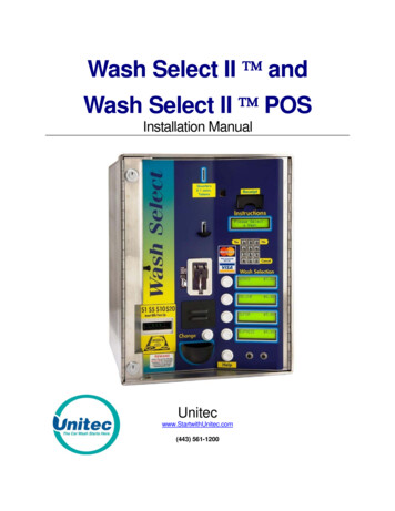
Wash Select II andWash Select II POSInstallation ManualUnitecwww.StartwithUnitec.com(443) 561-1200
W A S HS E L E C TI IWASH SELECT II INSTALLATION MANUALThis manual provides comprehensive operational procedures for the Wash Select II. In thismanual, we will discuss the setup, operation and maintenance of the Wash Select II.If further assistance is needed, please contact the distributor from which the product waspurchased.When calling for assistance, you must have the following information available:Wash Select II Serial Number:Distributor Name:C O P Y R I G H T 2012 Unitec, Incorporated. All rights reserved. No part of this book, including text, screenexamples, diagrams, or icons, may be reproduced or transmitted in any form, by any means(electronic, photocopying, recording, or otherwise) without prior written permission of Unitec,Incorporated.T R A D E M A R K SEnterlink, Wash Select II, Wash Select II POS, WashChange, VIP Wash Pass, CustomizedVIP Wash Pass, VIP Wash Coupons, Unitec, and the Unitec Logo are trademarks, servicemarks, or registered trademarks of Unitec, Incorporated.Givex is the registered trademark of Givex Incorporated.CoinCo is the registered trademark of Coin Acceptors, Inc.All other products, services, and company names are trademarks or registered trademarks oftheir respective owners.Document Number:Document Title:WS21001Wash Select II POS Installation Manual
W A S HS E L E C TTable of Contents1Site Planning .11.1 Electrical Planning.11.1.1Site Grounding Considerations: .11.1.2Electrical Requirements of the Wash Select II .11.2 Mechanical Planning .41.2.1Position of the Unit .41.2.2Mechanical Requirements.41.3 Miscellaneous Planning .521.3.1Precautionary Considerations .51.3.2Unpacking & Checking Parts.51.3.3Wash Select II – Option Packages.6Tools Required for Installation.72.1 Mechanical Installation Tools.72.2 Electrical Installation Tools .73Mechanical Installation .93.1 Bricking in the Wash Select II .93.2 Installation of the Optional Base .1043.2.1Preliminary Consideration .103.2.2Installation of the Wash Select II Unit.12Electrical Installation.154.1 Wiring the Modem (Option) .154.1.1At the Unit .154.1.2At the Phone Jack .154.2 Wiring for Internet Credit Clearance (Option) .164.3 Wiring for WashPay Integration or Kwik Trip (Option) .164.4 Wiring the Car Wash .174.4.1Wash Outputs .174.4.2Wash-In-Use .184.4.3Wash-Fault.194.5 Wire the POS4000 .194.6 Wiring 115 VAC Main Power .194.6.1Measure Wire Lengths .204.6.2Attach the Three-prong Connector.204.7 Wiring the Intercom .22Document Number:Document Title:WS21001Wash Select II POS Installation ManualiI I
W A S HS E L E C T4.7.1Connecting a 2-wire Intercom System .234.7.2Connecting a 3-wire Intercom System .234.7.3Connecting a 4-wire Intercom System .244.8 Wiring External Fleet Device Interface.2454.8.1Hook up to Washcard Control Box .244.8.2Hook Up to Express Key Control Box .254.8.3Hook Up to eWash Control Box .26Startup / Programming.285.1 Wash Setup.285.1.1Wash Prices .285.1.2Wash Names.295.2 Wash Interface .295.2.1Relay Stacking .295.2.2Relay Latching .295.2.3Relay Pattern .305.2.4Auto Out of Service Detect.305.2.5Wash Handshaking .315.2.6Wash Fault .315.2.7Out-of-Service Timer (OOS).315.3 Customer Interface Menu.315.3.1Customer Stacking.315.3.2Forced Selection .315.3.3Allow Upgrades .325.3.4Auto Selection Time .325.4 Connecting to a POS4000 .325.5 Multi-unit Fleet System (Optional Feature) .335.6 Tokens (Optional).345.7 Testing the Entry System .355.8 Testing the Washes .35Appendix A.Guide for Alternate Keypad Functions.38Appendix B.Recorded Speech Messages .40Appendix C.Paging Error Codes .44Appendix D.Additional Steps for Canadian WSII Install.46Appendix E.Single Gate Installation (Without Gate Controller).54Document Number:Document Title:WS21001Wash Select II POS Installation ManualiiI I
W A S HS E L E C TIndex of FiguresFigure 1. Conduits with Modem Line Layout. 2Figure 2. Conduits with Ethernet Cable Layout . 3Figure 3. Wash Select II Base Placement . 5Figure 4. Wash Select II Installation . 10Figure 5. Straight Base . 11Figure 6. Angled Base. 11Figure 7. Setting Anchor Bolts . 12Figure 8. Modem Wiring. 15Figure 9. IPTran and DataTran Connections . 16Figure 10. Ethernet Cable Wiring Inside the Wash Select II. 17Figure 11. AC Connector . 20Figure 12. Inside the AC Connector. 21Figure 13. Thread Power Cord Through Line Insulator . 21Figure 14. Line - Neutral - Ground Connections . 22Figure 15. Intercom Adaptor Board. 23Figure 16. Standard Wash Select II Keypad. 28Figure 17. Wash out of Service Sequence . 30Figure 18. Alternate Keypad Functions. 38Figure 19. Outside/Inside of IDX Coin Acceptor . 49Figure 20. Sample Site Layout. 54Figure 21. Gate Position . 56Figure 22. Gate Reset Loop Dimensions. 56Figure 23. Gate Base Bolt Positioning . 57Figure 24. Gate Wiring . 58Index of TablesTable 1. Wash Relays . 18Table 2. Wash-In-Use Signal . 18Table 3. Wash-fault SIGNAL. 19Table 4. POS4000 Connection . 19Table 5. J1 of Unitec Wash Card interface board . 24Table 6. J 2 of Unitec Wash Card interface board. 25Table 7. Washcard input assignments. 25Table 8. J1 of Unitec Wash Card interface board . 25Table 9. J 2 of Unitec Wash Card interface board. 25Table 10. 24 VAC Source Connection . 26Table 11. J1 of Unitec Wash Card Interface Board . 26Table 12. J2 of Unitec Wash Card Interface Board . 27Table 13. 24 VAC Connection . 27Table 14. POS 4000 Cable Connections . 32Table 15. Multi-Unit Fleet Cable Connections . 33Table 16. Remote Wash Select II Bay Addresses . 34Table 17. Pager Error Codes . 44Table 18. Wash Select II Token Values. 49Table 19. Canadian IDX Program Configuration . 50Document Number:Document Title:WS21001Wash Select II POS Installation ManualiiiI I
W A S H[ T H I SDocument Number:Document Title:P A G EI N T E N T I O N A L L YWS21001Wash Select II POS Installation ManualL E F TS E L E C TB L A N K ]ivI I
W A S HS E L E C TI I1 Site PlanningThe Wash Select II is a self-serve unattended automatic car wash entry system designedspecifically for the self-serve car wash market. The Wash Select II accepts various forms ofpayment, interacts with customers at the car wash entrance, and arms the car wash.It is important to consider a few points prior to the actual installation of the Wash Select II unit.Among these considerations are the correct running of electrical conduit, and the properpositioning of all of the carwash machines. In this section, these issues will be discussed indetail. When proper planning is implemented, the Wash Select II installation will go smoothly,and the unit will operate reliably.1.1 Electrical Planning1.1.1 Site Grounding Considerations:Make sure that the protective earth ground wire does not carry any motor return current. Onlythe neutral wire should carry return current.1.1.2 Electrical Requirements of the Wash Select IIThe Wash Select II will need to have 115-120 VAC on a 5-Amp dedicated breaker, whichshould be provided during wash construction. Most installers will have power supplied directlyfrom one of the three phases used to power the wash motors and controllers. If this method isused, special attention should be given to proper earth grounding at the unit, as well as in thebreaker panel.Generally, most car wash manufacturers use a five-wire system to provide the arming signalsfor the selected wash packages. This means that one common line and four arming inputwires are fed from the car wash’s Programmable Logic Controller (PLC) to the Wash Select IIunit. In addition to these five, a Wash-In-Use Hot and Wash-In-Use Neutral are required toreset the wash electronics. Typically, these are also provided by the PLC. It is important toconsider this fact when planning the conduit runs, because there will need to be 2 separateruns from the wash to the Wash Select II—one for AC power, and one for PLC Control Wires& Optional Phone connection. If you are connecting to a POS4000 then you should have anadditional conduit run to the POS4000 (C-store), unless you have the RF option.Another important point to remember is that the Wash Select II is equipped to accept creditcards, so a separate run may be required from the nearest phone jack to the main conduitrun. There is no guarantee that a credit upgrade will not be performed, so the installer shouldthink ahead and make provisions. If there is an undedicated phone line nearby, then everyattempt should be made to try to route the conduit so that access is easily gained to it. Forexample, a junction box can be placed in the run at that particular point.If an undedicated telephone line is not nearby, try to route the conduit so that one isaccessible at a later date. An important rule to remember is that the telephone cable shouldDocument Number:Document Title:WS21001Wash Select II POS Installation Manual1
W A S HS E L E C TI Inot be run in the same conduit as the main power lines. Telephone, as well as intercomconnections, can be run in the POS4000 connection conduit (Wash Select II POS system) ifyou are connecting to a POS4000 in a C-store.Figure 1. Conduits with Modem Line LayoutDocument Number:Document Title:WS21001Wash Select II POS Installation Manual2
W A S HS E L E C TI IFor Internet credit clearing, Kwik Trip, or WashPay integration, Ethernet cable will be needed.This cable should be standard CAT 5 or CAT 6. This cable can be pulled through the existingPOS4000 communications conduit run from the C-Store to the Wash Select II. The cableCANNOT be longer than 295 feet. The cable should extend at least 2 feet into the WSII andbe run into the back office of the store/office to the frame switch or router.Figure 2. Conduits with Ethernet Cable LayoutDO NOT RUN CABLE OUTSIDE OF A CONDUIT!Important:Follow all local and National Electric Codes.Finally, it should be understood that the Wash Select II unit is to be powered by wires of atleast 16 AWG, or larger. Failure to adhere to this recommendation could result in a fire orinjury. When installing the conduit, it is suggested that it be a minimum of ¾” in size, and bemade of metal versus PVC.Document Number:Document Title:WS21001Wash Select II POS Installation Manual3
W A S HS E L E C TI I1.2 Mechanical Planning1.2.1 Position of the UnitThe proper positioning of the Wash Select II unit is very important. Figure 2 of this sectionshould be used as a reference for good layout practices. There are several layoutconsiderations that follow, which may be a good idea to think about. They are meant forsuggestion only, and are not permission to circumvent wash manufacturer guidelines.The Wash Select II unit should be placed 10-14 feet from the car wash entrance to ensurethe proper timing and flow of customers. The wash’s treadle switch should be centered alongthe horizontal plane, approximately 18” inches out from the front of the Wash Select II unit.Note that the Wash Select II unit extends 6” out from the leading edge of the optional straightbase and even more for an angled base (refer to angled base dimensions). This will ensurethat the car/truck’s wheel is aligned with the treadle switch, as shown in Figure 2. Finally, aconcrete post can be positioned just to the front and left corner of the unit, to act as aprotective buffer. A typical size for this post is between 30 and 35 inches.1.2.2 Mechanical RequirementsIt is strongly recommended that the unit be surrounded with a brick or concrete housing formaximum security. However, since this may not be realistic in some installations, mounting iton a concrete slab will suffice.This manual assumes that the optional base will be installed simultaneously with the unit. Inthis case, the concrete should be a minimum of 5” inches thick, 21” inches wide, and 13”inches long (Refer to Figure 2). The dimensions and positioning of the mounting holes for thebase will be covered in the “Mechanical Installation” section of this manual.The front edge of the standard base should be 18 inches from the driver’s side tire centerline.(For angled bases, this distance should be 38.5 inches.) This provides the appropriatedistance for customers to comfortably reach the unit o make their selections.Document Number:Document Title:WS21001Wash Select II POS Installation Manual4
W A S HS E L E C TI IFigure 3. Wash Select II Base Placement1.3 Miscellaneous Planning1.3.1 Precautionary ConsiderationsA large percentage of sites contain “Floor Heat”. Floor heat is an under-concrete heatexchanger system, consisting of an elaborate network of plumbing, through which anti-freezecirculates. In many cases this plumbing can run beside, under, or over conduit. Beforemarking and drilling into any area, the site floor heat diagrams should be reviewed, and theappropriate action taken to prevent any damage.1.3.2 Unpacking & Checking PartsNote:If any parts are missing, please call Unitec Technical Services at 1-443-561-1200.Open each of the shipping boxes and ensure the following items are present:1 . 3 . 2 . 1 Wa s h S e l e c t I I – S t a n d a r d I n s t a l l at i o nWash Select II Main Case AssemblyAllen Wrench For DoorDocument Number:Document Title:WS21001Wash Select II POS Installation Manual5
W A S HS E L E C TI IInstallation & Operation ManualsKeys & Lock core set(4) Bolts to secure top assembly to optional base(4) Washers to be used on bolts for optional base1.3.3 Wash Select II – Option PackagesThe following items should be added to the standard installation checklist, if that specificoption was purchased with it.W A S HS E L E C TI I–C R E D I TO P T I O NExtra Roll of Thermal Printer PaperIPTran credit modemW A S HS E L E C TI I-S P E E C HO P T I O NMicrophone (for message recording)W A S HS E L E C TI IP R O X I M I T YS W I T C HO P T I O NInfrared Relay Block (installed on Wash Select II power supply cover)W A S HS E L E C TI I–O P T I O N A LB A S EBase(4) Concrete Anchor Bolts(4) Washers(4) NutsW A S HS E L E C TI I–W A S H P A YI N T E G R A T I O NCAT5E Ethernet CableExpansion boardDocument Number:Document Title:WS21001Wash Select II POS Installation Manual6
W A S HS E L E C TI I2 Tools Required for Installation2.1 Mechanical Installation ToolsIt is highly recommended that the Wash Select II be bricked in! All attempts should be madeto achieve that end. It is ultimately the responsibility of individual distributors to make thisdecision, and if the decision is made that it will not be possible, Unitec offers an optional baseat an affordable price. The following tools are recommended for the typical mechanicalinstallation of this Wash Select II unit and optional base:6” inch or longer ratchet extension (for optional straight base)¾” inch deep well socket and socket wrenchOpen end 9/16” inch wrenchSmall, thin blade, flat-tip screwdriverHammer drill½” Concrete hammer drill bitHammerDual-plane Level50’ foot tape measure2.2 Electrical Installation ToolsIn addition to the mechanical assembling of the Wash Select II unit to the base (and the entirepackage to the concrete), there will be a number of electrical connections, which must bemade. These connections will require the use of the following common electrical tools:Small, thin tipped, straight screwdriver (1/8” tip, for green Phoenix connectors)Wire strippers (capable of handling 10-22 AWG wire)Cable or wire tie wrapsDiagonal cuttersNeedle nose pliersTelephone wire crimping tool and 4-pin, RJ11 / 14 modular plugs (for modem, ifpresent) Radio Shack Part # 279-384Document Number:Document Title:WS21001Wash Select II POS Installation Manual7
W A S HDocument Number:Document Title:WS21001Wash Select II POS Installation ManualS E L E C T8I I
W A S HS E L E C TI I3 Mechanical InstallationUnitec recommends the bricking in of the WSII when installed on property that is notmanned or is not in plain sight of station or business personnel.Note:Unitec also recommends the connection of the WSII to a monitored security system inthese situations or any situation where vandalism or theft may occur.The use of the included door sensor and a customer supplied shock sensor mountedon the door is recommended as well.3.1 Bricking in the Wash Select IIFor optimum security the Wash Select II unit should be mounted on a concrete slab andbricked in.Tips on Bricking in:Conduit openings are at the right side of the bottom of the case.Bolt holes are at the bottom of the case to secure to the concrete slab.The concrete slab should be built so that the bottom of the Wash Select II case is32.5” from the floor.Outer dimensions of the Wash Select II are:Including reinforcingband along frontedgeNot including reinforcingband around front .26”19.25”The following drawing shows such an installation:Document Number:Document Title:WS21001Wash Select II POS Installation Manual9
W A S HS E L E C TI IFigure 4. Wash Select II InstallationHint:Most installers may need to increase the protection and organization of the wires thatrun from the conduit to the bottom of the Wash Select II main cabinet. Flexible conduitcan be used to perform this function. The connectors can be attached to the metalconduit by way of PVC cement.3.2 Installation of the Optional BaseThis document outlines the installation of the optional base.3.2.1 Preliminary ConsiderationThe Wash Select II base comes in two distinct styles, straight and angled. The followingprocedures are applicable to the straight base only. Refer to the documentation you receivedwith the angled base (MN1001 Angled Base Addendum) for installation procedures for theangled base.Document Number:Document Title:WS21001Wash Select II POS Installation Manual10
W A S HS E L E C TFigure 5. Straight BaseFigure 6. Angled Base1. Mark the 4 holes that you intend to drill in order to mount the Wash Select IIoptional base. Mark the holes with a marker as the base is sitting on top of theconcrete. It is important to keep in mind that the conduit run will need to protrudethrough the large opening in the lower right corner, at least 3 inches.Warning:Document Number:Document Title:DO NOT BEGIN MOUNTING OF THE BASE UNTIL ALL WIRES & CABLES HAVEBEEN PULLED THROUGH THE CONDUIT!WS21001Wash Select II POS Installation Manual11I I
W A S HS E L E C T2. Remove the base from the marked location and proceed to drill the holes, usingthe hammer drill, and the ½” inch concrete drill bit. Ensure that the holes aredrilled deep enough to insert the anchor bolts. A good depth is approximately 2”2½” inches from the surface of the concrete.3. It should be noted that while the anchor bolts are rugged and durable, they couldbecome damaged if struck recklessly. Care should be given to strike only the topof the anchors, where the force will be distributed by the provided area on top ofthe anchor bolt. Use the hammer to drive each of the provided anchors into thedrilled concrete holes.Figure 7. Setting Anchor Bolts4. When all anchor bolts have been set, place one nut onto each of them, and usethe ratchet and socket to tighten it, until as many of the threads from the bolts aspossible are showing. This firs
Wash Select II and Wash Select II POS Installation Manual Unitec www.StartwithUnitec.com (443) 561-1200