Transcription
51 Winthrop RoadChester, Connecticut 06412-0684Phone: (860) 526-9504Internet: www.whelen.comSales e-mail: autosale@whelen.comCustomer Service e-mail: custserv@whelen.comInstallation Guide:295SLS*6 Siren AmplifierDANGER! Sirens produce extremely loud emergency warning tones! Exposure to these tones without proper and adequate hearing protection, couldcause ear damage and/or hearing loss! The Occupational Safety & Health Administration (www.osha.gov) provides information necessary to determinesafe exposure times in Occupational Noise Exposure Section 1910.95. Until you have determined the safe exposure times for your specific application,operators and anyone else in the immediate vicinity should be required to wear an approved hearing protection device. Failure to follow thisrecommendation could cause hearing loss!Warnings to InstallersWhelen’s emergency vehicle warning devices must be properly mounted and wired in order to be effective and safe. Read and follow all of Whelen’s writteninstructions when installing or using this device. Emergency vehicles are often operated under high speed stressful conditions which must be accounted forwhen installing all emergency warning devices. Controls should be placed within convenient reach of the operator so that they can operate the system withouttaking their eyes off the roadway. Emergency warning devices can require high electrical voltages and/or currents. Properly protect and use caution aroundlive electrical connections.Grounding or shorting of electrical connections can cause high current arcing, which can cause personal injury and/or vehicledamage, including fire. Many electronic devices used in emergency vehicles can create or be affected by electromagnetic interference. Therefore, afterinstallation of any electronic device it is necessary to test all electronic equipment simultaneously to insure that they operate free of interference from othercomponents within the vehicle. Never power emergency warning equipment from the same circuit or share the same grounding circuit with radiocommunication equipment. All devices should be mounted in accordance with the manufacturer’s instructions and securely fastened to vehicle elements ofsufficient strength to withstand the forces applied to the device. Driver and/or passenger air bags (SRS) will affect the way equipment should be mounted. Thisdevice should be mounted by permanent installation and within the zones specified by the vehicle manufacturer, if any. Any device mounted in the deploymentarea of an air bag will damage or reduce the effectiveness of the air bag and may damage or dislodge the device. Installer must be sure that this device, itsmounting hardware and electrical supply wiring does not interfere with the air bag or the SRS wiring or sensors. Mounting the unit inside the vehicle by amethod other than permanent installation is not recommended as unit may become dislodged during swerving; sudden braking or collision. Failure to followinstructions can result in personal injury. Whelen assumes no liability for any loss resulting from the use of this warning device. PROPER INSTALLATIONCOMBINED WITH OPERATOR TRAINING IN THE PROPER USE OF EMERGENCY WARNING DEVICES IS ESSENTIAL TO INSURE THE SAFETY OFEMERGENCY PERSONNEL AND THE PUBLIC.Automotive: Sirens/SwitchesWarnings to UsersWhelen’s emergency vehicle warning devices are intended to alert other operators and pedestrians to the presence and operation of emergency vehicles andpersonnel. However, the use of this or any other Whelen emergency warning device does not guarantee that you will have the right-of-way or that otherdrivers and pedestrians will properly heed an emergency warning signal. Never assume you have the right-of-way. It is your responsibility to proceed safelybefore entering an intersection, driving against traffic, responding at a high rate of speed, or walking on or around traffic lanes. Emergency vehicle warningdevices should be tested on a daily basis to ensure that they operate properly. When in actual use, the operator must ensure that both visual and audiblewarnings are not blocked by vehicle components (i.e.: open trunks or compartment doors), people, vehicles, or other obstructions. It is the user’s responsibilityto understand and obey all laws regarding emergency warning devices. The user should be familiar with all applicable laws and regulations prior to the use ofany emergency vehicle warning device. Whelen’s audible warning devices are designed to project sound in a forward direction away from the vehicleoccupants. However, because sustained periodic exposure to loud sounds can cause hearing loss, all audible warning devices should be installed andoperated in accordance with the standards established by the National Fire Protection Association.Safety FirstThis document provides all the necessary information to allow your Whelen product to be properly and safely installed. Before beginning the installation and/oroperation of your new product, the installation technician and operator must read this manual completely. Important information is contained herein that couldprevent serious injury or damage.WARNING: This product can expose you to chemicals including Methylene Chloride which is known to the State of California to cause cancer, andBisphenol A, which is known to the State of California to cause birth defects or other reproductive harm. For more information go towww.P65Warnings.ca.gov. Proper installation of this product requires the installer to have a good understanding of automotive electronics, systems and procedures. Whelen Engineering requires the use of waterproof butt splices and/or connectors if that connector could be exposed to moisture. Any holes, either created or utilized by this product, should be made both air- and watertight using a sealant recommended by your vehiclemanufacturer. Failure to use specified installation parts and/or hardware will void the product warranty. If mounting this product requires drilling holes, the installer MUST be sure that no vehicle components or other vital parts could be damagedby the drilling process. Check both sides of the mounting surface before drilling begins. Also de-burr the holes and remove any metal shardsor remnants. Install grommets into all wire passage holes. If this manual states that this product may be mounted with suction cups, magnets, tape or Velcro , clean the mounting surface with a 50/50mix of isopropyl alcohol and water and dry thoroughly. Do not install this product or route any wires in the deployment area of your air bag. Equipment mounted or located in the air bag deploymentarea will damage or reduce the effectiveness of the air bag, or become a projectile that could cause serious personal injury or death. Refer toyour vehicle owner’s manual for the air bag deployment area. The User/Installer assumes full responsibility to determine proper mountinglocation, based on providing ultimate safety to all passengers inside the vehicle. For this product to operate at optimum efficiency, a good electrical connection to chassis ground must be made. The recommendedprocedure requires the product ground wire to be connected directly to the NEGATIVE (-)battery post (this does not include products that use cigar power cords). If this product uses a remote device for activation or control, make sure that this device islocated in an area that allows both the vehicle and the device to be operated safely in anydriving condition. It is recommended that these instructions be stored in a safe place and referred to whenperforming maintenance and/or reinstallation of this product. FAILURE TO FOLLOW THESE SAFETY PRECAUTIONS AND INSTRUCTIONS COULD RESULTIN DAMAGE TO THE PRODUCT OR VEHICLE AND/OR SERIOUS INJURY TO YOU AND YOURPASSENGERS! 2008 Whelen Engineering Company Inc.Form No.14130J (100521)ACTIVATION OF THISSIREN MAY DAMAGEUNPROTECTED EARS!CAUTIONWearProtection!Loud siren noise can causehearing damage and/or loss.Refer to OSHA Section 1910.95 priorto putting ANY siren into service!For warranty information regarding this product, visit www.whelen.com/warrantyPage 1
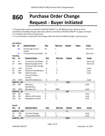
Congratulations on selecting the 295SLS-Series Siren. This series offers a unique collection of features designed to allow the user tocustomize the operation of this siren to suit their individual needs. Features include: Programmable Power Distribution Switches Power distribution control switch typeselection (push on push off, momentary,flashing, timed output) Power to drive two, 100-Watt Speakers Scan-Lock Power Distribution & Siren TonePrograming Auxiliary Input Control Siren Interruption Control Hands-Free Operation High and Low Voltage Shutdown Horn Ring Transfer Program the Siren Tone and the Override Tone ofany Rotary switch position Simulated mechanical Siren Tones Enabling or Disabling Auxiliary Siren from thepower distribution control switches “Siren In Use” Output Speaker Diagnostics LED Backlighting1.0 Mounting:This siren is designed to be mounted directly onto the dash or other surface throughthe use of a bail strap mounting bracket. The unit may also be mounted into yourvehicle’s console (if so equipped).WARNING: Regardless of the style selected, be sure to observe the air bagwarning on the cover of this manual. Harmonically-rich, composite Airhorn Tones Title XIII-Compliant Profiles Non-destructive Short Circuit Protection Meets Class A Sound Requirements External Back-light Control Radio Repeat Copy one units configuration to another unit Easy reset to default settings Power Distribution fuses included2. Connect the YELLOW wire to the POSITIVE terminal on SPEAKER #1 and theORANGE wire to the POSITIVE terminal on SPEAKER #2. NOTE: For singlespeaker installations use the YELLOW wire and cap the ORANGE wire.3. Connect BROWN wire to NEGATIVE connection on speakers #1 & 2.WHITE & GREY - Horn Relay Wires:1. Route WHITE and GREY wires along factory wire harness and through firewall atthe same point as the RED and BLACK wires.WARNING: Mounting this unit will require drilling. It is absolutely necessary tomake sure that no other vehicle components could be damaged in the process.Check both sides of the mounting surface before starting. If damage is likely,select a different location.2. Route WHITE and GREY wires to vehicle’s horn relay. If possible, follow thefactory wire harness to this relay.1.1 Bail Strap Mount:5. Connect the GREY wire to the wire coming from the horn.1. Position bail strap in selected mountinglocation and drill mounting holes, thensecure the bail strap to the vehicle.Two BLUE wires - Radio Rebroadcast (optional):3. Locate the wire that connects the vehicle horn to the horn relay and cut it.4. Connect the WHITE wire to the wire coming from the horn relay.The two remaining BLUE wires are used to connect your two-way radio’sexternal speaker for radio rebroadcast (optional connection).2. Secure the siren to the bail strap asshown. Tighten the acorn nuts firmly.Note: If your remote speaker is amplified (speaker has a power amp circuit),radio rebroadcast will not work and should not be used.1.2 Console Mount:Fig. 1Console manufacturers offer mounting kitsthat include all the necessary hardware andbrackets required to mount this unit into theirconsole. The console mount brackets aresecured onto the unit in the same way. Please refer to the manual included with yourconsole.1.3 Microphone Clip:1. Locate the 2 wires that connect the external speaker to the 2-way radio, cut one ofthem and splice one of the BLUE wires into this circuit.2. Cut the remaining speaker wire and splice the other BLUE wire into this circuit.VIOLET - Siren Interruption:Grounding the VIOLET wire will deactivate the siren. The siren can be programmedto reactivate the tones by 2 different methods (See section 6.8) This wire doesn’taffect HORN or MAN push button operations.2.2 3-Position Input Connector:A microphone clip is included with this product.WARNING: Refer to the Air Bag Warning before installing this clip.WARNING: All customer supplied wiresthat connect to the positive terminal of thebattery must be sized to supply at least125% of the maximum operating currentand FUSED at the battery to carry that load.DO NOT USE CIRCUIT BREAKERS WITHTHIS PRODUCT!TABLE 1Current Draw / AMPS2.1 Siren Input Connector - RED:Power - BLACK: Ground203040506070801215.510.57.5654.54Wire Gauge / AWG10 86424.5 39 62 98.516.5 26 41.5 6612.5 19.5 31 49.510 15.5 25 39.58 13 20.5 337 11 17.5 286 10 15.5 24.5215710478.56352.54539Distance is shown in feet.2.0 Wiring:1. Splice the 2 RED (Power) wires together,then extend this single RED wire toward thevehicle battery. Splice the 2 BLACK (Ground) wires together and extend thissingle BLACK wire toward the vehicle battery. To pass the RED and BLACK wiresthrough, you may have to drill a hole in the firewall. Insert a grommet to protect thewires.2. Route the RED and BLACK wires along the factory harness towards the batteryand install a fuse block (user supplied) on the end of the RED wire. Remove fusefrom fuse block before connecting any wires to battery.3. Connect fuse block wire to POSITIVE terminal on battery. There must not bemorethan 2 feet of wire between fuse block and battery. The wire between the fuseand battery is “unprotected”. Do not allow it to chafe and short to ground.4. Connect the BLACK wire to the factory chassis ground.ORANGE, YELLOW & BROWN - Speaker Wires1. Route the ORANGE, YELLOW and BROWN wires toward vehicle siren speakers,along factory wire harness and through firewall at the same point as the RED andBLACK wires.Page 2
3 Pos. Slide Switch: 0 Off 1 Controls Terminal 12 Controls Terminal 2 3 Controls Terminals 3, 4 & 5Push ButtonsProgrammable PowerDistribution Control564Fig. 3Slide Switches321321Siren Input sTerminal8ControlsTerminal9ControlsTerminalsPIN / WIRE / GAGE / FUNCTIONControlsTerminal1 RED / 14GA ( ) BATTERY10-11-12 13-14-1515 14 13 12 11 10 9 8 7 6 5 4 3 2 12 BLK / 14GA (-) GROUND3 BLU / 18GA125 BLK / 14GA (-) GROUND36 BLU / 18GARADIO7 BRN / 16GASPKR COM20 Amp FuseRear View of Siren8 ORG / 16GA ( ) SPKR #2SIREN9 VIO / 18GA INTERRUPT10 GRY / 18GAPowerSwitchManualRotarySwitchRadio RepeatAdjusts volume3 Position ConnectorAirMicrophone Mic.Horn VolumeInputPINCOLORFUNCTIONBACKLIGHTING1 WHT/YEL2 WHT/ORG SIREN IN USE OUTPUTAUX. ENABLE3 WHT/GRNHORNScan-Lock F u s e 11 WHT / 18GA HORN/RINGButton:Holder 12 YELYEL //16GA16GA( ) Speaker # 1Momentary switch.Use a non-conductiveitem to push in.3.6 SI TEST & Diagnostic IndicatorsWHITE/GREEN - Aux Enable:This wire is activated by switching it to ground (see section 4 for operation).WHITE/ORANGE - Siren in Use:Extend the WHITE/ORANGE to the icon input of a video camera. This wire is activepositive whenever a siren tone is being produced (200ma max).WHITE/YELLOW - Backlighting:Extend the WHITE/YELLOW to the parking light positive voltage. This input is usedto drive the backlighting of the siren when the power is off.2.3 Main Power wires - 10 AWG:RED - Power / 12VDC:1. Extend the two 10 AWG RED wires along the vehicle factory wire harnesstowards the battery. Install a 60 AMP fuse block (user supplied) on the ends ofeach of these wires (see table 1 for correct wire size).WARNING!RADIO4 RED / 14GA ( ) BATTERYRemove the fuse from the fuse block before connecting anywires to the battery.2. Connect each fuse block wire to the positive ( ) terminal of the battery. Theremust not be more than 2 feet of wire between the fuse blocks and the battery. Thewire between the fuse and battery is “unprotected,” do not allow it to chafe andshort to ground.SI TEST is a diagnostic feature of the 295SLS and allows the operator to confirm theproper operation of the siren speakers connected to the unit without activating anaudible siren tone. To initiate SI TEST cycle, set the rotary knob to the RAD position.Now press and release the MAN button. As the siren is tested, its diagnostic indicatorwill turn on steady for about 1.5 seconds if no problems are detected. If the indicatorflashes, or does not light at all, a problem with either the siren, speakers, or wiringhas been detected. Check the wire connections of the failed speaker and repeat theSI TEST. If the speaker fails to test again, have the siren itself inspected by a qualified technician. NOTE: Installed speakers are tested by generating an ultra-high frequency tone through each speaker. Although these tones are inaudible to humans,be sure no one is within 5 feet of the speakers when SI TEST is running.Diagnostic Indicators:While this siren is under normal use the diagnostic indicators are used to indicatefault conditions with your siren system. The following table lists the type of fault andthe indicators response. If the indicator is on steady while a tone is in use, thisimplies that there is no fault with the associated speaker output.Fault Condition Diagnostic Indicators ResponseUnder Voltage Speaker LED #2 will be in a DoubleFlash mode (2 quick flashesfollowed by a longer pause) and siren tones won’t operate.Over VoltageSpeaker LED #1 will be in a DoubleFlash mode (2 quick flashesfollowed by a longer pause) and siren tones will not operate.This switch has two positions; Up (On) and Down (Off). When this switch is off, sirenfunctions are disabled, however the power distribution switching can be programmedto operate independently of the power switch (default) or activate only when thepower switch is on (see section 6.6).Speaker #1Short CircuitSpeaker LED # 1 will be in a SingleFlash mode (the LED will be onand off an equal amount of time) and siren tones won’t operate.Speaker #2Short CircuitSpeaker LED #2 will be in a SingleFlash mode (the LED will be onand off an equal amount of time) and siren tones won’t operate.WARNING!If the 295SLS is connected to the vehicle’s horn ring circuit, thevehicle horn is disabled when the power switch is ON.Speaker #1Open CircuitSpeaker LED #1 will be off (having a single speaker system willalways cause this condition for the speaker output not in use) alltones will continue to operate.Speaker #2Open CircuitSpeaker LED #2 will be off (having a single speaker system willalways cause this condition for the speaker output not in use) alltones will continue to operate.3.0 Front Panel:3.1 Power Switch3.2 Rotary SwitchThe Rotary Knob controls the siren functions of the 295SLS. There are 7 positionsthat may be selected (see Section 4.0.).3.3 Volume KnobThe Volume Knob controls the volume of Public Address function. Volume isincreased by rotating the knob in a clockwise direction. Rotating the Volume Knob ina counter-clockwise direction decreases the volume produced by these features. Thevolume knob has no effect on siren tones or radio repeat volume.3.4 Radio Repeat VolumeBefore using the 295SLS, the Radio Repeat output volume must be adjusted to satisfactory operating levels. To adjust this level, a small, flat-blade screwdriver isneeded. Locate the Radio Repeat adjustment port (potentiometer) to the right of theRotary Knob on the face of the control head. Set the volume level of the vehicle’stwo-way radio to its normal operating volume. Turn the Rotary Knob on the controlhead to RAD to activate Radio Repeat. Insert the screwdriver in the Radio Repeatadjustment port and turn in a clockwise direction to increase the sound level.3.5 MAN ButtonThe Manual button generates a variety of tones, depending on what position therotary knob is in (see Section 4.0.).3.7 Horn ButtonPower up the siren and hold the HORN button on to generate an AIRHORN tone.3.8 Programmable Power Switches:The power distribution switches include the slide switch and the six momentaryswitches. The slide switch having one off position and three active positions combined with the six momentary switches makes a total of nine switch positions. Foreach of the nine switches there are corresponding outputs on the terminal block inthe back of the unit. Each of the nine switches will always activate it’s own corresponding output, but can be programmed to activate any of the other outputs and/oractivate the siren as well (see Section 6.0).3.9 Microphone:Whenever the siren is on, activating the microphone (pressing the switch on the sideof the mic.) will shut down any other siren functions and enable public addressoperation regardless of the rotary switch position or any other switch or input.Page 3
4.0 Rotary Switch Operations:This section will outline the operation of the siren in the factory defaultconfiguration. Refer to Section 6.3 for information on how to customize theoperation of this siren.4.1 RAD - Radio Repeat:When the rotary knob is in the RAD position, anysignal that is received by the vehicle’s two-way radio will be simultaneouslybroadcast over the vehicle’s loudspeaker (the unit must be connected to the two-wayradio as outlined in this manual).With the Rotary Switch in this Position:Pressing the MAN button will start SI TEST as described in Section 3.6. Activating the HORN RING input will produce the AIRHORN tone until theHORN RING switch is released. Activating the AUX ENABLE input has no effect.4.2 MAN 1 - Manual Siren #1: When the rotary switch is in this position thesiren is in a standby state where no tones have been activated, but is waiting foranother action to be taken by the operator.With the Rotary Switch in this Position: Activating the HORN button will produce the AIRHORN tone until released. Pressing the MAN button will produce the AIRHORN tone until the MAN switchis released. Activating the HORN RING input will produce the AIRHORN tone until theHORN RING input is released. 4.3 MAN 2 - Manual Siren #2: When the rotary switch is in this position thesiren is in a standby state. No tones will be activated until another action is taken bythe operator.With the Rotary Switch in this Position: Activating the HORN button will produce the AIRHORN tone until released. Pressing the MAN switch will produce a WAIL tone. This tone will ramp up topeak frequency and stop when the MAN switch is released. Activating the HORN RING input will produce a WAIL tone. This tone will rampup to peak frequency and stop when the HORN RING input is released. Activating AUX ENABLE will produce a repeating WAIL tone until AUXENABLE input is released.4.4 HF - Hands-Free Operation -When the rotary knob is in the HFposition, the siren functions are placed in a stand-by mode. Siren tones are activatedby a single “tap” on the MAN button or on the vehicle’s steering wheel horn ring (if thevehicle’s horn has been wired to the HORN RING input). The first tap produces a“Wail” tone (a steady rise and fall tone). A second tap produces a “Yelp” tone (a fastrise and fall tone). A third tap produces a “Piercer ” tone (an extremely fast rise andfall tone). The next tap returns the siren to a Wail tone and the cycle repeats itself.Two quick successive taps will stop the siren.With the Rotary Switch in this Position:Activating the HORN button will produce the AIRHORN tone until released. Pressing the MAN button will produce the HF cycle. Activating the HORN RING input will produce the HF cycle. Activating the AUX ENABLE input will start the HF cycle. Releasing the AUXENABLE will stop the cycle.4.5 T1 - Tone #1: When the rotary knob is in the T1 position, a steady, rise andfall tone (WAIL) is produced.With the Rotary Switch in this Position:Activating the AUX ENABLE input has no effect.4.8 T3 - Tone #3: When the rotary knob is in the T3 position, an extremely fast,rise and fall tone is produced.With the Rotary Switch in this Position: Activating the HORN button will produce the AIRHORN tone until released. Pressing the MAN button will result in the AIRHORN tone until released. Pressing the HORN RING input will result in the AIRHORN tone until theHORN RING input is released. Activating the AUX ENABLE will have no effect.5.0 Terminal Operation5.1 Terminal SpecificationsThis siren contains 15 screw terminals located in the upper rear panel of the housing.They are designed to activate components that do not exceed specific current draw.NOTE: It is important that any components connected to these terminalsdo not exceed the maximum current rating for that terminal.Warning! Total power distribution current is not to exceed 80 AMPS.1. . .2. . .3, 4 & 5. .6. . .7. . .8. . .9. . .11 . . . . . .12 . . . . . .14 . . . . . .15 . . . . . .Activating the HORN button will produce the AIRHORN tone until released. Pressing the MAN button will change the siren tone to a yelp pattern (a fast riseand fall tone). Pressing the MAN button a second time returns it back to WAIL. Activating the HORN RING input will change the siren tone to YELP. Activatethe HORN RING input again to return to WAIL. Activating the AUX ENABLE input has no effect.4.6 T2 - Tone #2: When the rotary knob is in the T2 position, a fast, rise and fall(Terminals 11 & 14 are always on unless otherwise noted)In the factory default configuration terminal outputs of the siren are:Slide Switch Positions:Push-Button Switches:0 Terminals OFF4 Terminal #6 ON1 Terminal #1 ON5 Terminal #7 ON2 Terminals #1 & 2 ON6 Terminal #8 ON3 Terminals #1, 2, 3, 4 & 5 ON7 Terminal #9 ON8 Terminal #12 ON / Terminal #11 OFF9 Terminal #15 ON / Terminal #14 OFF5.2 Custom Fuse Configurations: Push-Buttons 5 & 6Functionality(Fuse Locations / Section 7.0)Terminals #10 & 13 do notfunction as output terminals andare not used in the defaultconfiguration. By changing thepositions of specific fuses, theseterminals can be configured tocontrol auxiliary circuits. Theseauxiliary circuits can not exceed15 amps each.Fig. 415 AMPF8F8AAUX CIRCUITPOWER INN/C10NO15 AMP12F9AAUX CIRCUITPOWER INN/C1113Moving Fuse #8 from its default14position (F8) to its optionalNO15position (F8A) allows pushbutton 5 to control an auxiliarycircuit. Connect Power In from the aux. circuit to Terminal #10 and Load Out toTerminal #11 or 12. Push-button 5 will now open and close this circuit.Moving Fuse #9 from its default position (F9) to its optional position (F9A) allowspush-button 6 to control an auxiliary circuit. Connect Power In from the aux. circuit toTerminal #13 and Load Out to Terminal #14 or 15. Push-button 6 will now open andclose this circuit.With the Rotary Switch in this Position: Fuse20 Amps . . . . . . . . . . . . . . . . . . . . . . . . . . . . . . . . . . . . . . . . . . . . F120 Amps . . . . . . . . . . . . . . . . . . . . . . . . . . . . . . . . . . . . . . . . . . . . F220 Amps Total: These terminals can’t be activated individually . . F315 Amps . . . . . . . . . . . . . . . . . . . . . . . . . . . . . . . . . . . . . . . . . . . . F415 Amps . . . . . . . . . . . . . . . . . . . . . . . . . . . . . . . . . . . . . . . . . . . . F515 Amps . . . . . . . . . . . . . . . . . . . . . . . . . . . . . . . . . . . . . . . . . . . . F615 Amps . . . . . . . . . . . . . . . . . . . . . . . . . . . . . . . . . . . . . . . . . . . . F715 Amps15 Amps . . . . . . . . . . . . . . . . . . . . . . . . . . . . . . . . . . . . . . . . F8/F8A15 Amps15 Amps . . . . . . . . . . . . . . . . . . . . . . . . . . . . . . . . . . . . . . . . F9/F9AF9 tone (YELP) is produced. Terminal Max. LoadActivating the AUX ENABLE input will produce a repeating WAIL tone untilAUX ENABLE input is released. Activating the HORN RING input will produce the PIERCER tone. Pressing theHORN RING input a second time returns it back to YELP.RELAY8 RELAY9Activating the HORN button will produce the AIRHORN tone until released.Pressing the MAN button will produce the PIERCER tone. Pressing the MANswitch a second time returns it back to YELP.V BAT RED 10 AWG Activating the HORN button will produce the AIRHORN tone until released.Page 4
6.0 Programming the 295SLS*6:3.WARNING: Never try to program the siren while it is wired to the vehicle. Thesiren must be removed from the vehicle before programming. A low level audiodevice is built into the siren so siren tones can be heard during programming. Press and release the HORN switch to cyclethough the switch types (table 2).6.1 Power Distribution Switch Output Programming: Stop when indicator lights equal desired pattern.The lighting control switches include the slide switch and 6 momentary switches. Theslide switch has 1 off position and 3 active positions. Combined with the 6 momentaryswitches, that’s a total of 9 active switches. For each of the 9 switches there is a corresponding output on the terminal block. Each of the 9 switches activates its own corresponding output, but can also be configured to activate any of the other outputs and/or activate the siren.To Configure a Switch's Outputs:Turn the POWER switch OFF.Place the SLIDE SWITCH in the OFF position. Place the ROTARY SWITCH into the HF position. Hold the Scan-Lock switch in while turning power on.1OffOffOnOn2OffOnOffOnLED Speaker IndicatorPush On Push OffTimed OutputMomentaryFlashing OutputStore the Selected Switch's Output Pattern. Press the microphones PUSH TO TALK switch. The Speaker #1 indicator light will begin to flash, all other indicator lights will turnoff, and the data will be stored. When done programming, turn power off and then on to activate the changes.With Scan-Lock, the tonal operation of the siren can be customized to fit yourneeds. Scan-Lock is used to change the default siren tones as shown below.1. Put the unit into "switch output" configuration mode. Table 26.3 Siren Tone Programing ProceduresFor programming, connect positive ( ) battery and ground only. 4.Choose a switch type for theselected switch:To change the primary tone for rotary switch positions T1, T2. & T3 Press and continue to hold the switch to be configured.Put the rotary switch in the positionthat you wish to change. Each timethe Scan-Lock switch is pressedand released, the next availabletone will be broadcast. When thedesired tone is heard, it isautomatically sav
secure the bail strap to the vehicle. 2.Secure the siren to the bail strap as shown. Tighten the acorn nuts firmly. 1.2 Console Mount: Console manufacturers offer mounting kits that include all the necessary hardware and brackets required to mount this unit into their console. The console mount brackets are secured onto the unit in the same way.