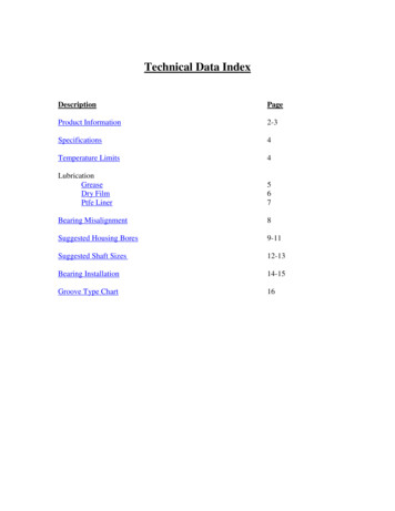
Transcription
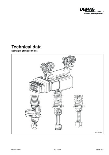
Technical dataDemag D-SH SpeedHoist42374245.eps060510 enEN203 533 44714 IS 852
ManufacturerDemag Cranes & Components GmbHP.O. Box 67 · 58286 Wetter (Germany)Telephone 49 (0) 2335 92-0 · Telefax 49 (0) 2335 927676www.demagcranes.comContents1Technical data1.1Design overview31.2Explanation of size designation31.3Selection table31.4Hoist motor data31.5Dimensions41.6Control units81.7Part numbers92General data102.1Assembling the trolley102.1.1 KBK I, KBK II, Aluline classic 120 and 180 trolley3102.1.2 CF 5 trolley, flange width 50 – 91 mm with load bar112.1.3 RU trolley, flange width 50 – 90 mm with load bar122.2Suspension heights, rope132.3Interface for load handling attachment132.4Power supply152.4.1 Connector protection152.4.2 Emergency-stop153Setting the parameters173.1Software terminal brief instructions173.1.1 Description17173.2Operating terminal accessories183.3Overview18 Demag Cranes & Components GmbH3.1.2 Connection2D-SH SpeedHoist operating instructions211 151 44DC-Pro operating instructions214 741 44DC-Pro technical data203 525 44DCS-Pro technical data203 525 44D-SH Speedhoist brochure213 054 44D-SH SpeedHoist flyer213 125 4420353344.indd/060510Part no.:Accompanying documents
1Technical data1.1 Design overview432155769 10811 1242584645.eps1.2 Explanation of sizedesignation1Electrical equipment cover2Gearbox housing8Lifting limit switch3Bracket9Rope drum4Analogue PWM converter10Drum axle5Frame11Cover plate6Fan cover12Switching rod7Rope guideD-SH 80SWL 80 kg or 160 kgSizeD-SH 80D-SH 160Demag SpeedHoist1.3 Selection tableSizeSWLFEMLifting speedm/min Demag Cranes & Components GmbHkg1.4 Hoist motor data801 Ammax. 70D-SH 1601601 Ammax. 35WeightkgKDP 63 B 230Required supply cable conductor cross sections and fuse linksGroup of mechanisms to FEMKDP 63 B 21 AmRated current IN and start-upcurrent IAfor 50 Hz20353344.indd/060510V1D-SH 80Motor size400 V DP1) The lengths of the supply lines are calculatedon the basis of an earth-loop impedance of200 mΩ.Motor sizeIN (A)IA (A)4,2up to 1,5 x INVoltageCE/CSAPCDFncos ϕ50/60 HzkW%rpmN380 - 480 V0,943047500,67cosϕ0,67Mains connectiondelay fusefor 50 HzSupply cables for 5% voltage dropand start-up current IA for 50 Hz 1)400 V DP400 V ( U 20 V)Amm2m101,51533
1.5 Dimensions215105M83551)Rope outlet highesthook positionRope outlet lowesthook position3915020345ø207015 Demag Cranes & Components GmbH1051521433071518816493M82153661) Load bar for KBK trolleys, optional, part no. 851 195 44442586146.eps20353344.indd/060510640
D-SH hoist with two KBK I or KBK II trolleys and manual force control1/1 reevingLoad bar, part no.: 851 195 44SWL 80 kg KBK I355850853150459093Load barRope travelm highestm/nn lowesthook position42586247.epsSizeD-SH 80D-SH 1601/1Hook pathFoot hole distanceHighesthook positionLowesthook positionmmn2,23993The D-SH hoist with D-Grip should not be used in connection with a conductor lineintegrated in the KBK rail, since the manual force required for the D-SH hoist withD-Grip is lower than the force required for displacing the current collector.20353344.indd/060510 Demag Cranes & Components GmbHNote:Reeving5
D-SH hoist with two KBK I or KBK II trolleys and rocker switch1/1 reevingLoad bar, part no.: 851 195 44SWL 80 kg KBK I355CC150459093Load barRope travelm highestm/nn lowesthook position42772844.epsC(with quick-change coupling)2,8 m745 mm2,8 m770 mm4,3 m(Standard)795 mm4,3 m(Standard)820 mmD-SH 80D-SH 160Reeving1/1Hook pathDistance to foot holewithhelical cablewithhelical cableHighesthook positionLowesthook position4,3 m2,8 mmn2,2 m2,2 m3993 Demag Cranes & Components GmbHSize6Helical cableC(with C hook)20353344.indd/060510Helical cable
D-SH hoist with two KBK I or KBK II trolleys and DSM Manulift handle1/1 reevingLoad bar, part no.: 851 195 44SWL 80 kg KBK I355823755150459093Load barm/nRope travelm highestn lowesthook position42772944.epsSizeD-SH 801/1Hook pathFoot hole distanceHighesthook positionLowesthook positionmmn2,2399320353344.indd/060510 Demag Cranes & Components GmbHD-SH 160Reeving7
1.6 Control unitsD-Grip with quick-change couplingRight-angle plug“Grip occupied” displayLeft buttonRight buttonStatus LEDLight barrierQuick-change coupling42534244.epsRocker switch with quick-change couplingEmergency-stop e coupling Demag Cranes & Components GmbHSwitching rocker
Rocker switch with C hookEmergency-stop buttonSwitching rockerLoad hook42376144.epsDSM Manulift quick-change coupling21 DSM Manulift2 Top cover3913 Emergency-stop switch40144 Actuating rockers5 Quick-change coupling540215744.eps1.7 Part numbersPart no.Designation Demag Cranes & Components GmbH929 005 46929 004 46Rocker sw. C hook929 012 46Manulift quick-change coupl.929 000 46D-Grip929 009 46D-SH 80Rocker sw. quick-change coupl.929 008 46Rocker sw. C hook929 014 46Manulift quick-change coupl.929 002 46D-Grip929 007 46Rocker sw. quick-change coupl.929 006 46Rocker sw. C hook929 013 46Manulift quick-change coupl.929 011 46Operating Frequencyvoltage [V][Hz]RemarkRocker sw. quick-change coupl.929 001 4620353344.indd/060510Control380 - 48050 / 60USA designUSA emerg.stop, externalD-GripD-SH 160Rocker sw. quick-change coupl.929 010 46Rocker sw. C hook929 015 46Manulift quick-change coupl.929 003 46D-GripEmerg. stop,external380 - 48050 / 60Emerg. stop,externalUSA designUSA emerg.stop, external9
2General data2.1 Assembling the trolley2.1.1 KBK I, KBK II, Aluline classic120 and 180 trolleyThe D-SH can either be mounted using the threaded bore holes of the housingflange or by connecting it to a load bar (see below).KBK II trolley with pinKBK I trolley with pin1141401044.eps41400944.epsAluline classic 120 trolley with pinAluline classic 180 trolley with pin1142589744.eps42589844.eps11295342627Tightening torque25 Nm38 Demag Cranes & Components GmbH938106 Hex. socket screw M 8 X 222 Washer A21 x 37 x 37 Washer 8 x 16 x 23 Washer 20 x 32 x 4KBK I and KBK II8 KBK I, KBK II, Aluline classic 120 and 180 pins4 Tube 20 x 2 x 22KBK I9 BoClip5 Load bar20353344.indd/06051042783044.eps1 Trolley with pin
2.1.2 CF 5 trolley, flange width 50 – 91 mm with load bar1234586711741665545.eps9820353344.indd/060510 Demag Cranes & Components GmbH10 Tightening torque11 25 Nm42783144.eps1CF 5 click-fit trolley7Head pin 12H11 x 30 slot2Retaining clip SL 10 SXN088Retaining clip SL 12 SXN083CF5 retaining elements9CF5 trolley crossbar4Head pin 10 x 64,8 slot10 Hex. socket screw M 8 x 225Tube 16 x 2,8 x 2911 Washer 8 x 16 x 26CF5 suspension eye bracket11
2.1.3 RU trolley, flange width 50 – 90 mm with load barTighteningtorque 50 NmTightening torque50 Nm41665744.eps23Tightening torque25 Nm1312122Side cheek travel wheel univ. no toothed rim8Washer 16,5X 25 X 43D-SH load bar9Load bar RU 3 cpl. (items 7, 8, 10, 11)4Load capacity plate 450 kg10 Pin RU 3 load bar5RU 3DK travel wheel universal11 Tube 26,9 x 2,65 x 316Sleeve 12,1 x 27 x 912 Hex. socket screw M 8 X 227Hex. nut M16 x1,513 Washer 8 x 16 x 220353344.indd/06051042783244.eps Demag Cranes & Components GmbH2
2.2 Suspension heights,ropeThe standard rope length of the D-SH is 11 m including the safety windings on therope drum. The rope length is divided into 1,25 m of safety windings which alwaysremain on the drum, 2,2 m max. hook path and 7,5 m of dead rope.The standard rope length of the D-SH is 11 m including the safety windings on therope drum. The length is divided into 1,3 m of safety windings which always remainon the drum, 2,2 m max. hook path and 7,5 m of dead rope. The rope is an easilybending rope, particularly suitable if the rope is to be returned via additional ropesheaves.If larger rope lengths are required, a longer rope can be ordered for this specificapplication (please state when ordering).A special stainless steel rope is also available (requires shorter maintenance intervals). All ropes measure 5 mm in diameter.The manual force control system is provided with a helical cable, standard length2,8 m (extended), for transmitting the electrical signals of the D-Grip unit. Thislimits the suspension height to max. 3,8 m from the lower edge of the travel rail.Larger suspension heights require a special helical cable which must be specifiedadditionally in your order (please specify suspension height). Shortening the helicalcable will not result in a reduction of the C dimension.The rocker switch as well as the DSM Manulift are supplied with a helical cablehaving a standard length of 4,3 m (extended). This results in a max. suspensionheight of approx. 5 m – from the lower edge of the travel rail.For a C dimension reduced by approx. 50 mm, a helical cable with a length of approx. 2,8 m (extended) is also available.The interface of the load handling attachments is identical on all control units withquick-change coupling for D-SH, the control units can be exchanged.2.3 Interface for loadhandling attachmentNote: When exchanging the control unit (change from D-Grip to rocker switch orDSM Manulift) the connection assignment must be changed.111DSM Manulift with swivel unitand rope socket111Rocker switch solo and with swivel unitand rope socket111D-Grip solo and with swivel unit andrope 0510Ø8 Demag Cranes & Components GmbH159042543644.eps42737644.eps42789244.eps13
For the quick-change coupling on D-Grip, rocker switch or DSM Manulift the loadhandling attachments known from the Demag DC chain hoist range are available(see DSM Manulift example below).The elements can be connected at the bottom of the individual D-Grip, rockerswitch or DSM Manulift units.For further load handling attachments for the quick-change coupling see DemagDC chain hoist technical data 203 525 44.Load handling attachment on DSM Manulift, 1Item10,5M12Swivelling loadhook 250 kgCoupling pin250 kgØ2085Gripperhook 125 kgBelt sling125 kgSWLPart no.Weight565 695 440,651565 696 44-[kg]Open hook2Belt slingBelt sling width 45 mm, max. dia. to be gripped 430 mm3Crane hook adapter with quick-changecouplingThe adapter for the crane hook also makes it possible to useManulift load handling attachments on other hoists.718 332 454Load hookIncluded in the standard scope of delivery835 665 445Swivelling load hook6Coupling pinFor fitting individual load handling attachments7Manulift articulated jointPantograph tongs swivel adapter814[kg]1125718 333 450,9500,317835 584 440,608835 580 440,084The articulated joint prevents the chain from twisting betweenthe chain hoist and the Manulift control unit.835 669 440,324The swivel adapter for SZ 1 2 pantograph tongs enables thetongs to be turned freely on the DSM Manulift.717 330 450,41925020353344.indd/060510Description Demag Cranes & Components GmbH42789344.epsItem Designation
2.4 Power supplyVoltage (CE/CSA)380 V – 480 V AC 3-phase, 50/60 Hz.USA 460 V 60 Hz.2.4.1 Connector protectionA protective plate is available for the D-Grip (part no. 773 235 44), which protectsthe right-angle plug against damage. The protective plate is galvanized.Protective plate (option)42540844.eps2.4.2 Emergency-stopIf D-SH hoists are provided with rocker switch or DSM Manulift, no external emergency stop is required. The emergency-stop button is integrated in the rockerswitch or the DSM Manulift.20353344.indd/060510 Demag Cranes & Components GmbH(1)42707744.jpg40215745.eps15
For operation of the D-SH hoist with the D-Grip, an external emergency-stop device must be provided. It is applied on terminals X2.1 and X2.2 in the analoguePWM converter of the D-SH.It is useful to determine the position of the emergency stop device in line with thespecific system, e.g. integrated in the operating elements of a load handling attachment or of a lifting mast.Externalemergency stop 1) D-Grip Rocker switch DSM ManuliftInverterAnalogue PWMconverter 2)Control boardMotorBrakeFanPulsegeneratorLifting limitswitchLoweringlimit switch42777444.epsSelect one of the following alternatives:a) Emergency stop via surface switchPart no.: 792 407 441) only for D-Grip. The emergency stop is integrated in the control unit when a rocker switch or the DSMManulift handle is fitted.162) only for D-Grip20353344.indd/060510 Demag Cranes & Components GmbHb) The emergency stop device is provided by the customer and integrated in theinstallation
3Setting the parameters3.1 Software terminalquick-step instructions3.1.1 DescriptionThe default parameters are selected so that the SpeedHoist is ready for operation.In many applications, this may already be the optimum setting.In addition, the D-SH features two different possibilities of setting parameters toadapt the SpeedHoist to specific applications.Further parameters may be changed and/or system statuses and operating datamay be recorded by means of the parameter setting set (720 905 45), also available as an option, in conjunction with a laptop or via the manual operating terminal(537 414 84).Setting parameters via a laptop or the manual operating terminal may only be carried out by instructed specialist personnel.The parameter setting set (part no. 720 905 45) comprises: RJ12 modular cable (5 m), RJ12/DSUB9 adapter (blue dot) for PC / laptop, RJ12/DSUB9 adapter (red dot) for operating terminal, CD-ROM with Softterm program.3.1.2 ConnectionFor setting the parameters of the D-SH you will need a PC / laptop.20353344.indd/060510 Demag Cranes & Components GmbHA further possibility of setting the parameters is provided by our operating terminalUPBT2-A00 from our accessories. See section 3.242738344.jpgThe program is controlled by the mouse or the keyboard.17
3.2 Operating terminal accessoriesUPBT2-A00 operating terminal (part no. 537 414 84)RUNERRORF42520944.eps3.3 OverviewThe following schematic illustration provides an overview of all components required for the control system.Externalemergency stop 1) D-Grip Rocker switch DSM ManuliftInverterAnalogue PWMconverterBrake
D-SH hoist with two KBK I or KBK II trolleys and manual force control 1/1 reeving SWL 80 kg KBK I 42586247.eps Size Reeving Hook path Foot hole distance Highest hook position Lowest hook position mm n D-SH 80 1/1 2,2 39 93 D-SH 160 Load bar Load bar, part no.: 851 195 44 Rope travel m highest n lowest hook position The D-SH hoist with D-Grip should not be used in connection with a .