Transcription
HP ProLiant ML350 G6 ServerUser GuideAbstractThis document is for the person who installs, administers, and troubleshoots servers and storage systems. HP assumes you are qualified in theservicing of computer equipment and trained in recognizing hazards in products with hazardous energy levels.Part Number: 513503-003February 2011Edition: 3
Copyright 2009, 2011 Hewlett-Packard Development Company, L.P.The information contained herein is subject to change without notice. The only warranties for HP products and services are set forth in the expresswarranty statements accompanying such products and services. Nothing herein should be construed as constituting an additional warranty. HP shallnot be liable for technical or editorial errors or omissions contained herein.Microsoft, Windows, and Windows Server are U.S. registered trademarks of Microsoft Corporation.
ContentsComponent identification . 7Front panel components . 7Front panel LEDs and buttons . 8Rear panel components . 9Rear panel LEDs and buttons . 10System board components . 11System board LEDs . 13NMI functionality . 14System maintenance switch . 14SAS/SATA device numbers . 15SAS and SATA hard drive LEDs. 16SAS and SATA hard drive LED combinations . 17Battery pack LEDs . 18FBWC module LEDs . 19Fan locations and configurations . 20Operations. 24Power up the server . 24Power down the server . 24Extend the server from the rack . 24Remove the server from the rack . 25Access the server rear panel (rack model). 25Open or remove the tower bezel . 25Remove the access panel. 26Install the access panel. 27Remove the media bay blank . 27Remove the large redundant fan air baffle . 27Remove the DIMM baffle . 28Remove a fan blank . 29Setup. 30Optional installation services . 30Optimum environment . 30Space and airflow requirements . 30Temperature requirements . 31Power requirements . 32Electrical grounding requirements . 32Rack planning resources. 32Rack warnings . 33Contents of the tower server shipping carton . 33Contents of the rack server shipping carton . 33Installing hardware options . 34Setting up a tower server . 34Installing the server into the rack. 35Powering up and configuring the server . 36Installing the operating system. 36Registering the server . 36Contents3
Hardware options installation . 37Introduction . 37Processor option. 37Memory options . 44Memory subsystem architecture . 44Single-, dual-, and quad-rank DIMMs . 45DIMM identification . 45Memory configurations. 46General DIMM slot population guidelines . 48Installing DIMMs . 51SAS or SATA hard drive option . 52Hard drive cage options . 54Installing a hard drive expansion cage power cable . 54Eight-bay SFF drive cage option . 57Two-bay LFF drive cage option . 59Removable media device options . 62Identifying guide screws . 62Installing a half-height or full-height media device . 62Installing the full-height media device shipping screw . 64Redundant fan assembly option . 65Redundant hot-plug power supply option . 66Power supply configuration . 67Installing the redundant hot-plug power supply option . 67Expansion board options. 69Removing the expansion slot cover . 69Installing an expansion board . 70PCI-X expansion cage option . 71Battery-backed write cache option . 78FBWC module and capacitor pack option . 80150W PCIe video/graphics controller power cable option . 82HP Trusted Platform Module option . 84Installing the Trusted Platform Module board . 85Retaining the recovery key/password . 86Enabling the Trusted Platform Module. 87Tower-to-rack conversion option . 87Configuration and utilities . 91Configuration tools . 91SmartStart software . 91HP ROM-Based Setup Utility . 92Array Configuration Utility . 94Option ROM Configuration for Arrays . 95Re-entering the server serial number and product ID . 95Management tools . 96Automatic Server Recovery . 96ROMPaq utility . 96Integrated Lights-Out 2 technology . 96Erase Utility . 97Redundant ROM support . 97USB support and functionality . 97Internal SD support . 98Diagnostic tools . 98HP Insight Diagnostics . 98Contents4
HP Insight Diagnostics survey functionality . 98Integrated Management Log . 99Remote support and analysis tools . 99HP Insight Remote Support software . 99Keeping the system current . 100Drivers . 100ProLiant Support Packs . 100Operating System Version Support . 100Change control and proactive notification . 100Care Pack . 101Troubleshooting . 102Troubleshooting resources . 102Pre-diagnostic steps . 102Important safety information . 102Symptom information . 104Prepare the server for diagnosis . 104Loose connections . 106Service notifications . 107Server health LEDs . 107Troubleshooting flowcharts . 107Start diagnosis flowchart . 107General diagnosis flowchart . 108Server power-on problems flowchart . 110POST problems flowchart . 113OS boot problems flowchart . 115Server fault indications flowchart . 116POST error messages and beep codes . 118Battery replacement . 120Regulatory compliance notices . 121Regulatory compliance identification numbers . 121Federal Communications Commission notice . 121FCC rating label . 121Class A equipment. 121Class B equipment . 121Declaration of conformity for products marked with the FCC logo, United States only . 122Modifications . 122Cables . 122Canadian notice (Avis Canadien) . 122European Union regulatory notice . 123Disposal of waste equipment by users in private households in the European Union . 123Japanese notice . 124BSMI notice . 124Korean notice . 124Chinese notice . 125Laser compliance . 125Battery replacement notice. 125Taiwan battery recycling notice . 126Power cord statement for Japan. 126Acoustics statement for Germany (Geräuschemission) . 126Electrostatic discharge . 127Preventing electrostatic discharge . 127Contents5
Grounding methods to prevent electrostatic discharge . 127Server specifications . 128Environmental specifications . 128Mechanical specifications . 128Power supply specifications . 128Technical support . 131Before you contact HP. 131HP contact information . 131Customer Self Repair . 131Acronyms and abbreviations . 139Index . 142Contents6
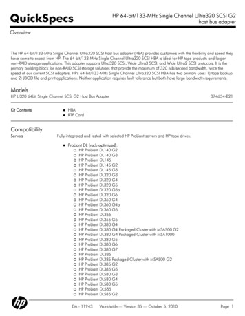
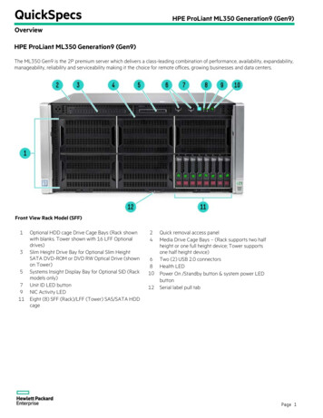
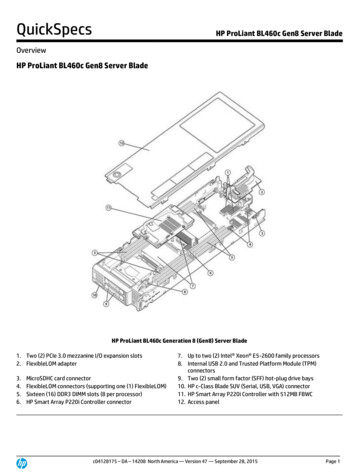
Component identificationFront panel componentsItemDescription1Power On/Standby button2UID button3USB connectors (2)4Hot-plug hard drive bays (8-bay SFF drive cage model)5Removable media bays6Optical driveComponent identification 7
Front panel LEDs and buttonsItemDescriptionStatus1System power LEDGreen Power onFlashing green Waiting for power due to group power cappingAmber System in standby, but power still appliedOff Power cord not attached or power supply failure2Health LEDGreen NormalAmber System degraded. To identify the component in a degradedstate, see the system board LEDs (on page 13).Red System critical. To identify the component in a critical state, seethe system board LEDs (on page 13).Off Normal (when in standby mode)3Power cap LEDGreen Power cap configuredFlashing amber Power cap exceededOff Server in standby or power cap disabled4NIC 1 activity LEDGreen Network linkFlashing Network link and activityOff No link to network. If power is off, view status on the rear panelRJ 45 LEDs ("Rear panel LEDs and buttons" on page 10).5NIC 2 activity LEDGreen Network linkFlashing Network link and activityOff No link to network. If power is off, view status on the rear panelRJ 45 LEDs ("Rear panel LEDs and buttons" on page 10).6UID LEDBlue ActivatedFlashing System managed remotelyOff DeactivatedComponent identification 8
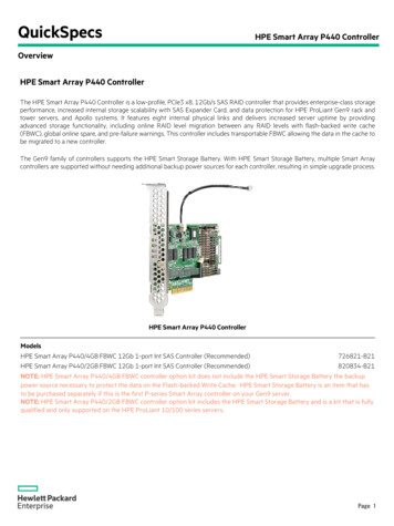
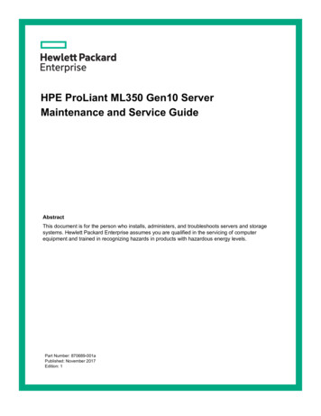
Rear panel componentsItemDescription1Power supply bay 22Keyboard connector3Power supply bay 1 (populated)4Video connector5USB connectors (2)6RJ-45 Ethernet connectors (2)7Slot 1 PCIe2 x8 (4, 2, 1)¹8Slot 2 PCIe2 x8 (4, 2, 1)²9Slot 3 PCIe2 x8 (8, 4, 2, 1)³10Slot 4 PCIe2 x16 (8, 4, 2, 1) 75W EXT 75W411Slot 5 PCIe2 x8 (4, 2, 1)12Slot 6 PCIe2 x8 (4, 2, 1)13RJ-45 Ethernet connector (dedicated iLO 2 management)14Serial connector15Mouse connector¹The SAS expander and the HP NC522SFP Dual Port 10GbE Server Adapter are not supported in slot 1.²HP recommends the SAS expander is installed in slot 2.³The HP NC522SFP Dual Port 10GbE Server Adapter is only supported in slot 3.Component identification 9
4To support options beyond 75W, install the 150W PCIe video/graphics controller power cable option (on page 82).Rear panel LEDs and buttonsItemDescriptionStatus1Power supply 2 LEDGreen Power supply is on and functioning.Off AC power is not available or AC power supply has failed.2UID LEDBlue ActivatedFlashing blue System managed remotelyOff Deactivated3Power supply 1 LEDGreen Power supply is on and functioning.Off AC power is not available or AC power supply has failed.4iLO 2 link LEDGreen Linked to networkOff Not linked to network5iLO 2 activity LEDGreen or flashing Network activityOff No network activity6NIC 2 link LEDGreen Linked to networkOff Not linked to network7NIC 2 activity LEDGreen or flashing Network activityOff No network activityComponent identification 10
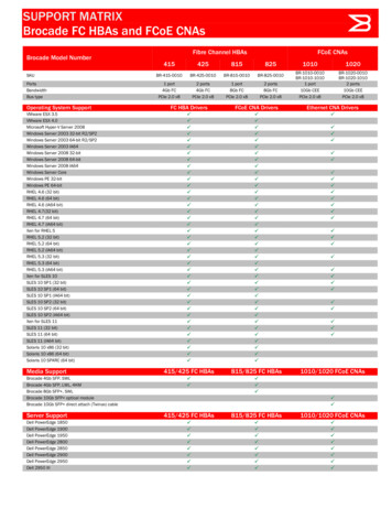
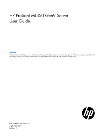
ItemDescriptionStatus8NIC 1 link LEDGreen Linked to networkOff Not linked to network9NIC 1 activity LEDGreen or flashing Network activityOff No network activitySystem board componentsItemDescription1Processor 1 DIMM slots2Power supply backplane connector3Processor socket 24System fan 4 connector5System power connectors6Processor 2 DIMM slots7System fan 3 connector8SD card slot (non-hot-plug)9System maintenance switch10Front panel LED board connector11SAS connector B12SAS connector A13HP Smart Array P410i memory connectorComponent identification 11
ItemDescription14TPM connector15SATA connectors (6)16Slot 1 PCIe2 x8 (4, 2, 1)¹17Slot 2 PCIe2 x8 (4, 2, 1)²1810Gb sideband connector (MII 24-pin)19Slot 3 PCIe2 x8 (8, 4, 2, 1)³20Slot 4 PCIe2 x16 (8, 4, 2, 1) 75W EXT 75W421Slot 5 PCIe2 x8 (4, 2, 1)22Slot 6 PCIe2 x8 (4, 2, 1)23Internal USB connector24Internal USB tape connector25System battery26System fan 2 connector27Processor socket 128System fan 1 connector¹The SAS expander and the HP NC522SFP Dual Port 10GbE Server Adapter are not supported in slot 1.²HP recommends the SAS expander is installed in slot 2.³The HP NC522SFP Dual Port 10GbE Server Adapter is only supported in slot 3.4To support options beyond 75W, install the 150W PCIe video/graphics controller power cable option (on page 82).Component identification 12
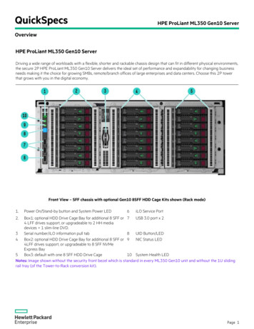
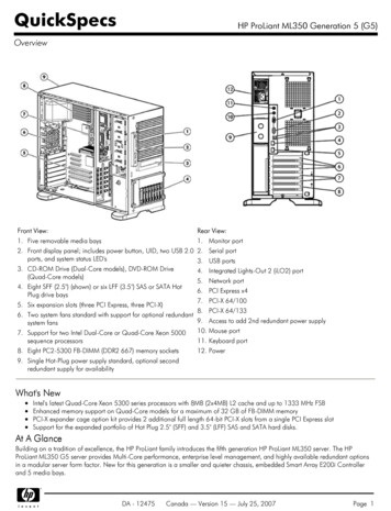
System board LEDsItemDescriptionStatus1Power supply 1Amber No AC power or failed power supplyOff Power supply is on and functioning.2Power supply 2Amber No AC power or failed power supplyOff Power supply is on and functioning.3Processor 2Amber Processor 2 failed.Off Processor 2 is functioning.4System fan 4Amber Fan is missing or has failed.Off Fan is functioning.5AMP statusGreen AMP mode is enabled.Amber Failover has occurred, or theconfiguration is not valid.Off AMP mode is disabled.6Processor 2 DIMMsAmber An error has occurred.Off Normal operation7System fan 3Amber Fan is missing or has failed.Off Fan is functioning.8OvertemperatureAmber System temperature threshold exceededOff Normal operation9System fan 2Amber Fan is missing or has failed.Off Fan is functioning.10Processor 1Amber Processor 1 failed.Off Processor 1 is functioning.Component identification 13
ItemDescriptionStatus11System fan 1Amber Fan is missing or has failed.Off Fan is functioning.12Processor 1 DIMMsAmber An error has occurred.Off Normal operationNMI functionalityAn NMI crash dump enables administrators to create crash dump files when a system is hung and notresponding to traditional debug mechanisms.Crash dump log analysis is an essential part of diagnosing reliability problems, such as hangs in operatingsystems, device drivers, and applications. Many crashes freeze a system, and the only available action foradministrators is to cycle the system power. Resetting the system erases any information that could supportproblem analysis, but the NMI feature preserves that information by performing a memory dump before ahard reset.To force the OS to invoke the NMI handler and generate a crash dump log, the administrator can do any ofthe following: Short the NMI jumper pins Press the NMI switch Use the iLO Virtual NMI featureFor additional information, see the whitepaper on the HP SupportManual/c00797875/c00797875.pdf).System maintenance switchPositionDe
¹The SAS expander and the HP NC522SFP Dual Port 10GbE Server Adapter are not supported in slot 1. ²HP recommends the SAS expander is installed in slot 2. ³The HP NC522SFP Dual Port 10GbE Server Adapter is only supported in slot 3. 4To support options beyond 75W, install the 150W PCIe video/graphics controller power cable option (on page 82).