Transcription
HP ProLiant ML350 Gen9 ServerUser GuideAbstractThis document is for the person who installs, administers, and troubleshoots servers and storage systems. HP assumes you are qualified in theservicing of computer equipment and trained in recognizing hazards in products with hazardous energy levels.Part Number: 781896-001September 2014Edition: 1
Copyright 2014 Hewlett-Packard Development Company, L.P.The information contained herein is subject to change without notice. The only warranties for HP products and services are set forth in the expresswarranty statements accompanying such products and services. Nothing herein should be construed as constituting an additional warranty. HP shallnot be liable for technical or editorial errors or omissions contained herein.Linux is the registered trademark of Linus Torvalds in the U.S. and other countries.Microsoft and Windows are U.S. registered trademarks of Microsoft Corporation.microSD is a trademark or a registered trademark of SD-3C in the United States, other countries or both.Red Hat is a registered trademark of Red Hat, Inc. in the United States and other countries.VMware is a registered trademark of trademark of VMware, Inc. in the United States and/or other jurisdictions.
ContentsComponent identification . 7Front panel components . 7Front panel LEDs and buttons . 10Rear panel components . 11Rear panel LEDs . 12System board components . 13System maintenanace switch . 14NMI functionality . 15DIMM slots . 15Using the System Insight Display . 16System Insight Display LEDs . 17System Insight Display LED combinations . 18Device numbering . 19Hot-plug drive LED definitions . 20Hot-plug fans . 21Operations. 23Power up the server . 23Power down the server . 23Remove the security bezel . 24Remove the tower bezel . 24Remove the access panel . 24Install the access panel . 25Extend the server from the rack . 26Remove the air baffle . 27Install the air baffle . 28Remove a fan . 29Remove the fan cage . 29Remove the optical drive . 30Remove a component drive cage blank . 31Setup. 33Optional installation services . 33Optimum environment. 33Space and airflow requirements . 33Temperature requirements . 34Power requirements . 35Electrical grounding requirements . 35Server warnings and cautions. 35Identifying server shipping carton contents . 36Installing hardware options . 36Setting up a tower server . 37Installing the server into a rack . 37Rack warnings . 42Installing the operating system . 43Powering on and selecting boot options in UEFI Boot Mode . 44Registering the server. 44Contents3
Hardware options installation. 45Introduction . 45Second processor option . 45Memory options . 50HP SmartMemory . 50Memory subsystem architecture . 51Single-, dual-, and quad-rank DIMMs . 51Population order . 52DIMM identification . 52Installing a DIMM. 52Install the security bezel . 54Install the optical drive . 54Tower to Rack conversion . 56System Insight Display Option . 60SFF media cage option . 63LFF media cage option. 68HP Smart Array controller Mini-SAS Y-cable option . 72Drive options . 76Removing a drive blank . 76Installing a hot-plug drive . 77Removing a drive . 78Graphic card option . 79Storage controller options . 83Installing the HP Flexible Smart Array Controller option . 84HP Smart Array Controller option . 86HP Smart Storage Battery . 87Installing a hot-plug redundant fan . 88Eight-bay SFF drive cage option. 91Eight-bay LFF drive backplane option . 94HP Trusted Platform Module option . 96Installing the Trusted Platform Module and security rivet . 96Retaining the recovery key/password. 97Enabling the Trusted Platform Module . 98Cabling . 99Media device data cabling . 99Optical device cabling . 100HP Flexible Smart Array Controller Mini-SAS cabling . 101HP Smart Array Controller Mini-SAS Y-cabling . 101Software and configuration utilities . 104Server mode . 104Product QuickSpecs. 104HP iLO . 104Active Health System . 105HP RESTful API support for HP iLO . 106Integrated Management Log . 106HP Insight Remote Support . 107Intelligent Provisioning . 107HP Insight Diagnostics . 108Erase Utility . 108Scripting Toolkit for Windows and Linux . 109HP Service Pack for ProLiant . 109HP Smart Update Manager . 109Contents4
HP UEFI System Utilities. 110Using HP UEFI System Utilities . 110Flexible boot control . 110Restoring and customizing configuration settings . 111Secure Boot configuration . 111Embedded UEFI shell . 112Embedded UEFI diagnostics . 112HP RESTful API support for UEFI . 112Re-entering the server serial number and product ID . 112Utilities and features . 113HP Smart Storage Administrator. 113ROMPaq utility. 113Automatic Server Recovery . 113USB support . 113USB support . 114Redundant ROM support . 114Keeping the system current . 115Drivers . 115Software and firmware . 115Version control . 115HP operating systems and virtualization software support for ProLiant servers . 116HP Technology Service Portfolio . 116Change control and proactive notification . 116Troubleshooting . 117Troubleshooting resources . 117Battery replacement . 118Regulatory information . 120Safety and regulatory compliance . 120Belarus Kazakhstan Russia marking. 120Turkey RoHS material content declaration . 121Ukraine RoHS material content declaration . 121Warranty information . 121Electrostatic discharge . 122Preventing electrostatic discharge . 122Grounding methods to prevent electrostatic discharge . 122Specifications . 123Environmental specifications . 123Server specifications . 123Power supply specifications . 124HP 500W Flex Slot Platinum Hot Plug Power Supply . 124HP 800W Flex Slot Platinum Hot Plug Power Supply . 125Support and other resources . 126Before you contact HP . 126HP contact information. 126Customer Self Repair . 126Acronyms and abbreviations . 134Documentation feedback . 138Index . 139Contents5
Contents6
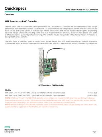
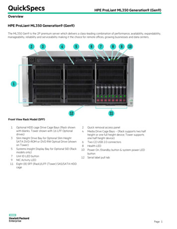
Component identificationFront panel components SFF model (Tower orientation)ItemDescription1SFF SAS/SATA drives2Serial number/iLO information pull tab13Drive cage bay4Optical drive bay5Media/drive cage bays6USB 2.0 connectors (2)Component identification7
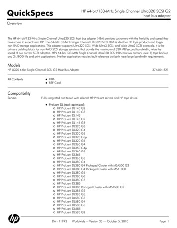
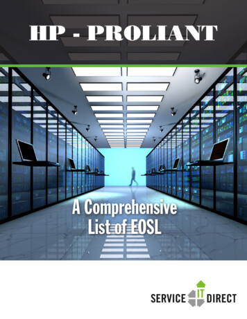
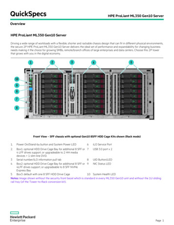
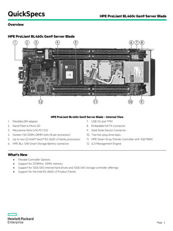
SFF model (Rack orientation)ItemDescription1SFF SAS/SATA drives2Serial number/iLO information pull tab13Drive cage bay4Optical drive bay5Media/drive cage bays6System Insight Display bay7USB 2.0 connectors (2)The serial number/iLO information pull tab is double-sided. The top side shows the server serial number, and the reverseside shows the default iLO account information. The same information is printed on a label attached to the chassis.1 LFF model (Tower orientation)Component identification8
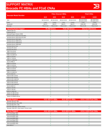
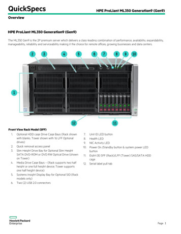
ItemDescription1Media/drive cage bay2Drive cage bay3Serial number/iLO information pull tab14LFF SAS/SATA drives5Optical drive bay6USB 2.0 connectors (2) LFF model (Rack orientation)ItemDescription1Media/drive cage bay2Drive cage bay3Serial number/iLO information pull tab14LFF SAS/SATA drives5Optical drive bay6USB 2.0 connectors (2)7System Insight Display bayThe serial number/iLO information pull tab is double-sided. The top side shows the server serial number, and the reverseside shows the default iLO account information. The same information is printed on a label attached to the chassis.1For more information on box and drive numbering, refer to Device numbering (on page 19).Component identification9
Front panel LEDs and buttonsItemDescriptionStatus1UID button/LEDSolid blue ActivatedFlashing blue: 1 Hz/cycle per sec Remote management orfirmware upgrade in progress4 Hz/cycle per sec iLO manual rebootsequence initiated8 Hz/cycle per sec iLO manual rebootsequence in progressOff Deactivated2Health LEDSolid green NormalFlashing green (1 Hz/cycle per sec) iLO isrebootingFlashing amber System degraded1Flashing red (1 Hz/cycle per sec) System critical13NIC status LEDSolid green Link to networkFlashing green (1 Hz/cycle per sec) Network activeOff No network activity4Power On/Standby button andsystem power LEDSolid green System onFlashing green (1 Hz/cycle per sec) Performingpower on sequenceSolid amber System in standbyOff No power present2To identify components in a degraded or critical state, see the Systems Insight Display LEDs, check iLO/BIOS logs, andreference the server troubleshooting guide.2Facility power is not present, power cord is not attached, no power supplies are installed, power supply failure hasoccurred, or the power button cable is disconnected.When all four LEDs described in this table flash simultaneously, a power fault has occurred.1Component identification10
Rear panel componentsItemDescription1Slot 1 PCIe3 x16 (8, 4, 1) (for Processor 1)2Slot 2 PCIe3 x8 (4, 1) (for Processor 1)3Slot 3 PCIe3 x16 (16, 8, 4, 1) (for Processor 1)4Slot 4 PCIe3 x8 (4, 1) (for Processor 1)5NIC connector 26NIC connector 47Serial connector8Slot 5 PCIe2 x8 (4, 1) (for Processor 2)9Slot 6 PCIe3 x16 (16, 8, 4, 1) (for Processor 2)10Slot 7 PCIe3 x8 (4, 1) (for Processor 2)11Slot 8 PCIe3 x16 (16, 8, 4, 1) (for Processor 2)12Slot 9 PCIe3 x8 (4, 1) (for Processor 2)13Power supply 414Video connector15Power supply 316iLO connector17NIC connector 318NIC connector 119Power supply 220USB 2.0 connectors (2)21USB 3.0 connectors (2)22Power supply 1Component identification11
Rear panel LEDsItemDescriptionStatus1NIC activity LEDGreen or flashing green Network activityOff No network activity2NIC link LEDGreen Linked to networkOff No network connection3Power supply LED (4)Green NormalOff One or more of the following conditions exists: PowerPowerPowerPoweris unavailable.supply failed.supply is in standby mode.supply exceeded current limit.4iLO link LEDGreen Linked to networkOff No network connection5iLO activity LEDGreen or flashing green Network activityOff No network activity6UID LEDSolid blue ActivatedFlashing blue: 1 Hz/cycle per sec Remote management or firmware upgradein progress4 Hz/cycle per sec iLO manual reboot sequence initiated8 Hz/cycle per sec iLO manual reboot sequence in progressOff DeactivatedComponent identification12
System board componentsItemDescription1slot9 PCIe3 x8 (4,1) (for Processor 2)2slot8 PCIe3 x16 (16,8,4,1) (for Processor 2)3slot7 PCIe3 x8 (4,1) (for Processor 2)4slot6 PCIe3 x16 (16,8,4,1) (for Processor 2)5slot5 PCIe2 x8 (4,1) (for Processor 2)6DIMM slots for Processor 17Processor 18slot4 PCIe3 x8 (4,1) (for Processor 1)9slot3 PCIe3 x16 (16,8,4,1) (for Processor 1)10slot2 PCIe3 x8 (4,1) (for Processor 1)11Slot1 PCIe3 x16 (8,4,1) (for Processor 1)12HP Smart Storage Battery connector13SATA port 414SATA port 515Internal USB 3.0 connector16x4 SATA port 217x4 SATA port 118Internal USB 2.0 connector19Flexible Smart Array Controller connector20Internal USB tape drive connector21Micro SD card slotComponent identification13
ItemDescription22DIMM slots for Processor 223HP System Insight Display connector24External thermal cable connector25Front IO connector2624-pin power supply connector27Processor 228RPS connector298-pin power supply connector30Fans connector31HP Smart Storage Battery connector32System battery33Discovery service connector34System maintenance switch35NMI header36TPM connector37HP Smart Storage Battery connectorSystem maintenanace switchPositionDefaultFunctionS1OffOff iLO security is enabled.On iLO security is disabled.S2OffOff System configuration can bechanged.On System configuration is locked.S5OffOff Power-on password is enabled.On Power-on password is disabled.S6OffOff Normal.On ROM reads system configurationas invalid.S7OffOff Set default boot mode to UEFI.On Set default boot mode to legacy.S10OffOff Tower configuration.On Rack configuration.S3, S4, S8,S9, S11, S12—ReservedTo access the redundant ROM, set S1, S5, and S6 to on.When the system maintenance switch position 6 is set to the On position, the system is prepared to erase allsystem configuration settings from both CMOS and NVRAM.CAUTION: Clearing CMOS and/or NVRAM deletes configuration information. Be sure toproperly configure the server or data loss could occur.Component identification14
IMPORTANT: Before using the S7 switch to change to Legacy BIOS Boot Mode, be sure the HPDynamic Smart Array B140i Controller is disabled. Do not use the B140i controller when theserver is in Legacy BIOS Boot Mode.NMI functionalityAn NMI crash dump creates a crash dump log before resetting a system which is not responding.Crash dump log analysis is an essential part of diagnosing reliability problems, such as failures of operatingsystems, device drivers, and applications. Many crashes freeze a system, and the only available action foradministrators is to restart the system. Resetting the system erases any information which could supportproblem analysis, but the NMI feature preserves that information by performing a memory dump before asystem reset.To force the system to invoke the NMI handler and generate a crash dump log, do one of the following: Use the iLO Virtual NMI feature. Short the NMI header ("System board components" on page 13).For more information, see the HP website (http://www.hp.com/support/NMI).DIMM slotsDIMM slots are numbered sequentially (1 through 12) for each processor. The supported AMP modes use theletter assignments for population guidelines.NOTE: The arrow indicates the front of the server.Component identification15
Using the System Insight Displa
HP ProLiant ML350 Gen9 Server User Guide Abstract This document is for the person who installs, administers, and troubleshoots servers and storage systems. HP assumes you are qualified in the servicing of computer equipment and trained in recognizing hazards in products with hazardous energy levels. Part Number: 781896-001 September 2014 Edition: 1