Transcription
Converting PLC-5 orSLC 500 Logic toLogix-Based Logic1756 ControlLogix Controllers1769 CompactLogix Controllers1789 SoftLogix Controllers1794 FlexLogix ControllersPowerFlex 700S DriveLogix ControllersReference Manual
Important User InformationBecause of the variety of uses for the products described in thispublication, those responsible for the application and use of thiscontrol equipment must satisfy themselves that all necessary stepshave been taken to assure that each application and use meets allperformance and safety requirements, including any applicable laws,regulations, codes and standards.The illustrations, charts, sample programs and layout examples shownin this guide are intended solely for purposes of example. Since thereare many variables and requirements associated with any particularinstallation, Allen-Bradley does not assume responsibility or liability(to include intellectual property liability) for actual use based uponthe examples shown in this publication.Allen-Bradley publication SGI-1.1, Safety Guidelines for theApplication, Installation and Maintenance of Solid-State Control(available from your local Allen-Bradley office), describes someimportant differences between solid-state equipment andelectromechanical devices that should be taken into considerationwhen applying products such as those described in this publication.Reproduction of the contents of this copyrighted publication, in wholeor part, without written permission of Rockwell Automation, isprohibited.Throughout this manual we use notes to make you aware of safetyconsiderations:ATTENTION!Identifies information about practices orcircumstances that can lead to personal injury ordeath, property damage or economic lossAttention statements help you to: identify a hazard avoid a hazard recognize the consequencesIMPORTANTIdentifies information that is critical for successfulapplication and understanding of the product.Allen-Bradley is a trademark of Rockwell Automation
Summary of ChangesSummary of ChangesThis document describes how to use the version of the translation toolthat is included with RSLogix 5000 programming software,version 10.0.Changes to this document include: When you select the source file to convert, the dialog box nowincludes a drop down menu where you select the type of Logixcontroller for the converted file. While RSLogix 5000 software now supports ASCII instructionsand a string data type, the translation tool does not convertASCII instructions to the Logix equivalents. You still have torework any converted ASCII instructions. See page 3-15 for moreinformation on how to rework PLC-5/SLC 500 ST data table files. These changes were made to the translation tool:Issue:Resolution:Empty strings and/or non-supportedNo comment is generated for an empty string in an address comment.symbols in address comment statements do Non-supported symbols in address comments (such as / : - \ # ] [ . @ & * ; ?not convert.( ) ) are converted to underscore ( ) symbols. The tool replaces consecutive underscoresymbols with one underscore symbol.IEEE format infinity or not-a-number valuesdo not convert.Infinity constants are translated to “1. ”Not-a-number constants are translated to “1.#QNAN”Infinity appears as 1.#INF0000e 000.Not-a-number appears as1.#NAN0000e 000.The generated .L5K file does not have an N:in front of each rung statement.The translation tool now puts N: in front of all rung statements. The N: prefix identifies therung as Normal. For examplePROGRAM Continuous (Main: mcpMain)ROUTINE mcpMain ()N: JSR( 2 LADDER, 0)END ROUTINEROUTINE 2 LADDER ()N: XIC(B3[0].0) OTE(B3[0].1);N: XIC(B3[0].0) OTE(B3[0].2);END ROUTINEEND PROGRAMIf there is no PROJECT statement in thePLC-5 or SLC file, the translation tool puts ablank project name in the controllerstatement. The generated .L5K file does notimport correctly with a blank name.1If there is a PROJECT statement in the import file, then the stated name is used as theproject name in the CONTROLLER statement.If there is no PROJECT statement in the import file, then the translation tool uses thename of the generated .L5K file as the project name.Publication 1756-RM085B-EN-P - November 2001
Summary of Changes2Notes:Publication 1756-RM085B-EN-P - November 2001
Table of ContentsChapter 1Converting a PLC-5 or SLC 500Program into a Logix ProjectIntroduction . . . . . . . . . . . . . . . . . . . . . . . . . . . . . . . . . .Comparing PLC-5 and SLC 500 architecture to Logixarchitecture . . . . . . . . . . . . . . . . . . . . . . . . . . . . . . . .Exporting a PLC-5 or SLC 500 Program. . . . . . . . . . . . . . .Using RSLogix5 or RSLogix500 programming software .Using 6200 series programming software . . . . . . . . . .Using A.I. series programming software . . . . . . . . . . .Converting a PLC-5 or SLC 500 Program. . . . . . . . . . . . . .View the Conversion Results . . . . . . . . . . . . . . . . . . . . . .Viewing the log file . . . . . . . . . . . . . . . . . . . . . . . . . .Import the ASCII Text File into a Logix Project . . . . . . . . .Rework PCE Instructions . . . . . . . . . . . . . . . . . . . . . . . . .Locating PCE instructions . . . . . . . . . . . . . . . . . . . . . .Rework UNK Instructions . . . . . . . . . . . . . . . . . . . . . . . .Configure the Controller and Chassis . . . . . . . . . . . . . . . .Map I/O . . . . . . . . . . . . . . . . . . . . . . . . . . . . . . . . . . . . .Complete MSG Configuration . . . . . . . . . . . . . . . . . . . . .Other Considerations. . . . . . . . . . . . . . . . . . . . . . . . . . . . 1-171-181-19.2-12-22-32-3Chapter 2Converting Program StructureIntroduction . . . . . . . . . . . . . . . . . . . . . . . . .Creating a Continuous Task. . . . . . . . . . . . . .Converting Selectable Timed Interrupts (STIs)Converting Input Interrupts (DIIs/PIIs). . . . . .Chapter 3Converting DataiIntroduction . . . . . . . . . . . . . . . . . . . . . . . . . . . . . . . . . . . 3-1How PLC-5 and SLC 500 import/export files identify datatable values . . . . . . . . . . . . . . . . . . . . . . . . . . . . . . . . . 3-2How Logix import/export files identify file types. . . . . . 3-2Converting Input (I) and Output (O) Data . . . . . . . . . . . . . 3-3Converting the Status (S) File Type . . . . . . . . . . . . . . . . . . 3-4Converting the Binary (B) File Type. . . . . . . . . . . . . . . . . . 3-5Converting the Timer (T) File Type . . . . . . . . . . . . . . . . . . 3-5Timer conversion rules. . . . . . . . . . . . . . . . . . . . . . . . . 3-7Converting the Counter (C) File Type . . . . . . . . . . . . . . . . 3-7Converting the Control (R) File Type . . . . . . . . . . . . . . . . . 3-8Converting the Integer (N) File Type . . . . . . . . . . . . . . . . . 3-9Converting the Floating Point (F) File Type . . . . . . . . . . . . 3-10Converting the ASCII (A) File Type . . . . . . . . . . . . . . . . . . 3-10Converting the Decimal (D) File Type . . . . . . . . . . . . . . . . 3-11Converting the Block-Transfer (BT) File Type. . . . . . . . . . . 3-11Block-transfer conversion rules. . . . . . . . . . . . . . . . . . . 3-12Publication 1756-RM085B-EN-P - November 2001
iiConverting the M0 and M1 File Types . . . . . . . . . . . . . . . . 3-12Converting the Message (MG) File Type. . . . . . . . . . . . . . . 3-13Message conversion rules. . . . . . . . . . . . . . . . . . . . . . . 3-14Converting the PID (PD) File Type . . . . . . . . . . . . . . . . . . 3-14Converting the ASCII String (ST) File Type . . . . . . . . . . . . . 3-15Converting the ControlNet (CT) File Type . . . . . . . . . . . . . 3-16Converting Constant Values. . . . . . . . . . . . . . . . . . . . . . . . 3-17Converting Indirect Addresses . . . . . . . . . . . . . . . . . . . . . . 3-17Converting indirect addressing on the file number. . . . . 3-18Converting Indexed Addresses. . . . . . . . . . . . . . . . . . . . . . 3-20Converting indexed addresses controlled by the processorstatus word S:24. . . . . . . . . . . . . . . . . . . . . . . . . . . . . . 3-20Converting indexed addresses that specify data in files(Logix arrays) . . . . . . . . . . . . . . . . . . . . . . . . . . . . . . . 3-20Converting Symbols . . . . . . . . . . . . . . . . . . . . . . . . . . . . . 3-21Converting Address Comments . . . . . . . . . . . . . . . . . . . . . 3-22Chapter 4Converting InstructionsIntroduction . . . . . . . . . . . . . . . . . . . . . . .Conversion Rules . . . . . . . . . . . . . . . . . . .Instruction List . . . . . . . . . . . . . . . . . . . . .Converting CAR instructions . . . . . . . . .Converting FOR/NXT/BRK instructions .4-14-14-24-164-16.A-1A-1A-2A-3Appendix AConversion MessagesPublication 1756-RM085B-EN-P - November 2001Introduction . . . . . . .Status Messages. . . . .Information MessagesQuestion Messages . .
Chapter1Converting a PLC-5 or SLC 500 Program into aLogix ProjectIntroductionRSLogix 5000 programming software includes a translation tool thatconverts a PLC-5 or SLC 500 import/export file (.PC5 or .SLCextension) into a complete import/export file (.L5K extension). Thismanual describes the translation tool that comes with release 8.0 ofRSLogix 5000 programming software.IMPORTANTCurrently, the translation tool converts only ladderinstructions. SFC and structured text files are notconverted.ATTENTION!After running the conversion process, the resultingimport/export file still requires further manipulation.You have to map the I/O and use BTD, MOV, orCOP instructions to place this mapped data into thestructures created by the conversion process.The translation tool produces a syntactically correct import/export file,but the exact intent of the original application could be lost. This losscould be due to differences between rules of precedence, indexedaddressing, I/O addressing, etc. The log file capturesthese differences.The goal of the translation tool is to reduce the amount of workinvolved in migrating a PLC-5 or SLC 500 program to a Logix project.The translation tool automatically converts the program logic, but it isnot the complete solution. Depending on the application, there isadditional work to make the converted logic work properly.1Publication 1756-RM085B-EN-P - November 2001
1-2Converting a PLC-5 or SLC 500 Program into a Logix ProjectThe entire conversion process involves:Conversion step:See page:Export the PLC-5 or SLC 500 program to an ASCII text file1-4Use the translation tool to convert the logic1-9View the conversion results1-10Import the ASCII text file into a Logix project1-13Rework PCE instructions1-14Rework UNK instructions1-16Configure the controller and chassis1-16Map I/O1-17Complete MSG configuration1-18Check other considerations1-19Comparing PLC-5 and SLC 500 architecture to Logix architectureThe Logix architecture differs in several ways from that of the PLC-5and SLC 500 processors. The translation tool converts this legacyarchitecture as it best fits into the Logix architecture. Because of thearchitectural differences, you must rework the converted Logix projectto make sure it operates properly.Publication 1756-RM085B-EN-P - November 2001
Converting a PLC-5 or SLC 500 Program into a Logix Project1-3Some of the most significant differences in architecture are:Architectural issue:Comparison:CPUThe PLC-5 and SLC 500 processor is based on 16-bit operations. Logix controllers use32-bit operations. The translation tool converts legacy logic into its 32-bit equivalent.operating systemThe PLC-5 and SLC 500 processors support individual program files that can beconfigured as selectable timed interrupts (STIs) or input interrupts (DIIs/PIIs). In addition,the PLC-5 processor supports multiple main control programs (MCPs). A Logix controllercombines these into it’s task, program, and routine organization. The translation toolconverts the legacy program types into appropriate Logix tasks.The PLC-5 and SLC 500 processors use an S data file to store processor status. A Logixcontroller stores data differently. Instead of accessing different locations within a file,you use Get System Value (GSV) and Set System Value (SSV) instructions to specify thestatus information you want. This is a significant difference that will require rework oncethe converted logic is imported into a Logix controller.The PLC-5 and SLC 500 processors also use bits in S:0 for the arithmetic status flags.For example, S:0/03 stores sign status. A Logix controller uses keywords to referencethese flags. For example, instead of referencing a bit address to monitor a signoperation, you use the keyword S:N.input and outputsThe PLC-5 and SLC 500 processor map I/O memory into I and O data table files. The I/Odata is updated synchronously to the program scan so you know you have currentvalues each time the processor begins a scan. A Logix controller references I/O which isupdated asynchronously to the logic scan. For a Logix controller, use the synchronouscopy (CPS) instruction to create an I/O data buffer to use for static values during logicexecution and update the buffer as needed.After the conversion is complete, you must add instructions to copy the I/O data into theI and O arrays. Do this at the beginning or ending of a program to buffer the data so thatit is presented synchronously to the program scan.dataThe PLC-5 and SLC 500 processors store all data in global data tables. You access thisdata by specifying the address of the data you want. A Logix controller supports datathat is local to a program and data that is global to all the tasks within the controller. ALogix controller can also share data with other controllers, and instead of addresses, youuse tags to access the data you want.Each PLC-5 and SLC 500 data table file can store several words of related data. A Logixcontroller uses arrays to store related data. The translation tool converts the PLC-5 andSLC 500 data table files into Logix arrays.timersThe PLC-5 and SLC 500 timers are based on their 16-bit architecture and can havedifferent time bases. A Logix controller is based on its 32-bit architecture and onlysupports a 1 msec time base. The translation tools converts the legacy timers as theybest fit into the Logix architecture. Converted timers might require rework to make surethey operate properly.communicationsThe PLC-5 processor supports block-transfer read and write (BTR and BTW) instructions,ControlNet I/O (CIO), and message (MSG) instructions. The SLC 500 processor supportsMSG instructions. The Logix controllers support MSG instructions. The translation toolconverts the legacy BTR, BTW, and MSG instructions into Logix MSG instructions. AnyCIO instructions are not converted. Once you import the converted logic, you mustconfigure the MSG instructions so that they work properly and rework any CIOinstructions.The rest of this manual describes the specifics of how thesearchitectural issues are converted.Publication 1756-RM085B-EN-P - November 2001
1-4Converting a PLC-5 or SLC 500 Program into a Logix ProjectExporting a PLC-5 orSLC 500 ProgramBefore you can convert PLC-5 or SLC 500 logic to its Logix equivalent,you must first export the logic to an ASCII text file with a .PC5extension for a PLC-5 file or a .SLC extension for an SLC 500 file. Ifyou select to convert comments and symbols as well, you also needthe .TXT file, which is the standard 6200 programming softwareformat for a documentation file.How you export the program to an ASCII text file depends on theprogramming software you use.Publication 1756-RM085B-EN-P - November 2001If you use:See page:RSLogix5 or RSLogix500 programming software1-56200 series programming software1-7A.I. series programming software1-8
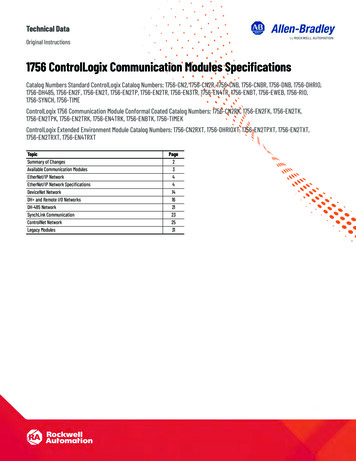
Converting a PLC-5 or SLC 500 Program into a Logix Project1-5Using RSLogix5 or RSLogix500 programming softwareCreate a .PC5 or .SLC file for the program file:1.Select File Save As.2.Select the program to export.Select the program to export.By default, the software points to the \Project folderfor the destination. You can enter a differentdestination directory.You must select the Library Files(.PC5 or .SLC) format.Select this option so that comments and symbolsare included in the export.Click Save.3.Select export options.Select Complete Program Save.Select all these options.Click OK.Publication 1756-RM085B-EN-P - November 2001
1-6Converting a PLC-5 or SLC 500 Program into a Logix ProjectCreate a .TXT file for comments and symbols:1.Select Tools Database ASCII Export.2.Select where to export comments and symbols.Select the AB 6200 format.Click OK.3.Select the directory where the .PC5 or .SLC file is.Click OK.4.Accept the warning about comments and symbols.Click OK.Publication 1756-RM085B-EN-P - November 2001
Converting a PLC-5 or SLC 500 Program into a Logix Project1-7RSLogix5 programming software stores PLC-5 programs using .RSP fileextensions. RSLogix500 programming software stores SLC 500programs using .RSS file extensions.Using 6200 series programming softwareTo export a program and its symbols using 6200 series programmingsoftware:1. Place the program files in \IPDS\ARCH\PLC52. Start 6200 series programming software.3. Select F7:File Utils F7:Export F1:Processor Memory FileOnly.4. Cursor to the program to export.5. Select F3:Select Source F1:Begin Operation.6. When the export process is complete, press any key to continue.7. Rename the log file in \IPDS\ARCH\PLC5 because the next stepwill overwrite the file.8. Select F7:File Utils F7:Export F3:Comments and Symbols.9. Use the cursors to select the program to export.10. Select F3:Select Source F1:Begin Operation.11. When the export process is complete, press any key to continue.12. Copy or move the .PC5/.SLC and .TXT files to where the Logixtranslation tool will find them.6200 software uses these file extensions for program files: .AC , .AF5,.B0 , .B1 , .D1 , .IX , .LX , .OP , .P1 , and .PC .Publication 1756-RM085B-EN-P - November 2001
1-8Converting a PLC-5 or SLC 500 Program into a Logix ProjectUsing A.I. series programming softwareTo export a program and its symbols using A.I. series programmingsoftware:1. Start A.I.5 series programming software.2. Select F1:Select Program/PLC-5 Address.3. Cursor to the program to export and press Enter.4. Select F5:Utility Options F1:Rebuild Damaged Data Base F1:Rebuild current program F1:Yes – Force rebuilding ofIndex files.5. When the rebuild process is complete, press any key tocontinue.6. Select F4:Export data base F4:6200 ASCII.7. Enter a name without an extension for the exported databasefile.8. When the database export is complete, press any key tocontinue.9. Press Esc to return to the main menu.10. Select F2:Offline Programming F3:Edit F2:Block F1:Block Start F2:Copy Block (it does not matter what isactually selected) F8:Save Block.11. Select F1:ASCII and enter a name without an extension for theexported program.12. Select F2:No Rung Descriptions. The translation tool usescomments from the .TXT file, not the .PC5/.SLC file.13. Select F3:Entire Program F4:No Annotation F5: No F7:Export. You do not need the “short description.”A.I.5 software uses these file extensions for program files: .ADR, .CEI,.CET, .CFG, .DSC, .IO2, .IO4, .PRF, .RCK, .RPD, .RPI, .SYM, .X5, .XRF,and .XRI.Publication 1756-RM085B-EN-P - November 2001
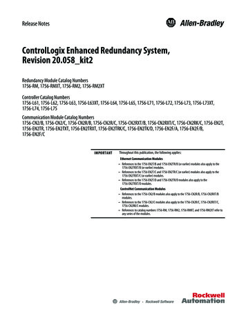
Converting a PLC-5 or SLC 500 Program into a Logix ProjectConverting a PLC-5 orSLC 500 Program1-9After you have the ASCII text file of the PLC-5 or SLC 500 program file,you can convert the logic to its Logix equivalent.Use RSLogix5000 programming software:1.Select Tools Translate PLC5/SLC.2.Select the text file to convert.Select the file to convert.It must have a .PC5 or .SLC extensionBy default, the software points to the\RSLogix5000\Project folder for the destination. Youcan enter a different destination directory.Note: Both the .PC5/.SLC and .TXT files must be in thesame directory for the conversion to work.Select conversion options.Select the controller type.Click Translate.This box displays the status of the conversion process.Click View Log to see the log file.Publication 1756-RM085B-EN-P - November 2001
1-10Converting a PLC-5 or SLC 500 Program into a Logix ProjectYou can select from these conversion options:Option:Description:Verbose logging modeCheck this option to write all messages of all categories to the log file. Otherwise, only asubset of the status messages and all of the question messages will be written to thelog file.Select Full to cause all messages of all categories to be written to the log file, in additionto extra, descriptive text.Select Partial to cause all messages of all categories to be written to the log file, withoutthe extra, descriptive text.Include comments and symbolsCheck this option to specify whether documentation is to be included in the conversion.By default, this option is enabled, causing the ASCII comment file .TXT to be processedalong with the processor program file.Important: The .TXT file must exist for the conversion process to operate when thisoption is selected.Important: Both the .PC5/.SLC and .TXT files must be in the same directory.View the ConversionResultsThe translation tool creates a complete import/export file (.L5Kextension) that you can then import into a Logix project. For moreinformation on the contents of a Logix import/export file, see theLogix5000 Controller Import/Export Reference Manual,publication 1756-RM084.After the conversion process, the import/export file followsthis format:CONTROLLER Controller Name TAG(* All tags, aliases, and associated descriptions areplaced here. *)END TAGPROGRAM Continuous ( MAIN : mcpMain )ROUTINE mcpMainJSR Routine Name ;%% More JSR calls could appear dependent uponprocessor type.END ROUTINE%% A routine is created for each ladder program thatexecutes.ROUTINE Routine Name (* A translated legacy ladder program *)END ROUTINEEND PROGRAMPublication 1756-RM085B-EN-P - November 2001
Converting a PLC-5 or SLC 500 Program into a Logix Project1-11PROGRAM Sti ( MAIN : Routine Name )ROUTINE Routine Name (* A translated legacy ladder program *)END ROUTINE%% A routine is created for each ladder program thatexecutes.END PROGRAMTASK Continuous ( MODE : CONTINUOUS, WATCHDOG : 500 )Continuous;END TASKTASK Sti ( MODE : PERIODIC, RATE : Rate , WATCHDOG : 500 )Sti;END TASKEND CONTROLLERThe components of the converted import/export file are:Component:Description:CONTROLLERThe conversion process creates one CONTROLLER structure.The controller name is based on the PROJECT statement in the PLC-5 import/export file.If the controller name is the same as any other instruction or keyword in the PLC-5import/export file, the conversion process appends DUP to the controller name.TAGThe conversion process creates one, controller-scoped TAG structure.All tags and aliases are placed in this global TAG structurePROGRAM ContinuousThe conversion process creates one PROGRAM named Continuos.This program holds all the routines.ROUTINE mcpMAINThe conversion process creates one ROUTINE names mcpMAIN.This routine contains the JSR instructions for one or more ROUTINES that are consideredthe main routines. The main routines are determined from PLC-5 processor status datathat identifies the main control programs.ROUTINEThe conversion process creates a ROUTINE for each PLC-5 program file.It is possible that JSR calls or processor status information may specify that the sameROUTINE is required by multiple PROGRAMS. If this occurs, the conversion processcreates duplicate ROUTINES, one for each PROGRAM that needs the ROUTINE.PROGRAM StiThe conversion creates this program for the STI logic, if is exists, for the PLC-5processor.TASK ContinuousThe conversion process creates one TASK to specify how to execute the programs. ThisTASK is always continuous and references the Continuous PROGRAM.TASK StiThe conversion creates this task to execute the STI logic. This is a periodic task thatreferences the STI PROGRAM.Publication 1756-RM085B-EN-P - November 2001
1-12Converting a PLC-5 or SLC 500 Program into a Logix ProjectViewing the log fileEach conversion process generates an ASCII-based log file. This logfile provides a summary of the conversion process, and containsformatted messages describing the actions and steps taken during theconversion process. The number and type of messages depend on theoptions you selected for the conversion process. The messages arewritten to the log file in the order in which their related translationactions occur.IMPORTANTThe log file identifies areas that should be examinedfor potential problems.You can open the log file from within the translation tool by pressingthe View Log button. You can also use any standard windows texteditor to open the log file. The name of the log file is the same as thename of the output file, but with a .LOG extension.The line numbers referenced in the log file correspond to the linenumbers in the exported PLC-5 or SLC 500 program file. Having aneditor that displays line numbers is helpful if you have to refer back tothe exported PLC-5 or SLC 500 program file.For more information about the messages that can appear in the logfile, see appendix A.Publication 1756-RM085B-EN-P - November 2001
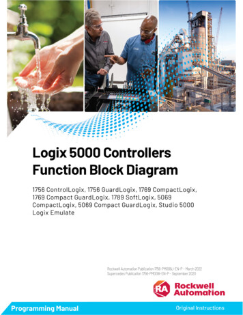
Converting a PLC-5 or SLC 500 Program into a Logix ProjectImport the ASCII Text Fileinto a Logix Project1-13The output file from the conversion process is a Logix import/exportfile with a .L5K extension. Import this file into a Logix project usingRSLogix5000 programming software.Use RSLogix5000 programming software:1.Select File Open.2.Select the text file.The text file should have a .L5K extension.Select the file to import.By default, the software points to the\RSLogix5000\Project folder. You can changethe default via Tool Options.Specify the name for the file to import.Click Open.3.Specify the name and location of the projectSpecify the project location.Specify the project name.Click Import.Publication 1756-RM085B-EN-P - November 2001
1-14Converting a PLC-5 or SLC 500 Program into a Logix ProjectRework PCE InstructionsThe conversion process inserts a PCE (Possible Conversion Error)instruction to identify possible errors. The PCE instruction followsthis format (in the ASCII text file):PCE( Message , PCETag )Where:Parameter:Description:Messageidentifies the type of error or warning that occurred.See appendix A for a list of possible conversion messages.PCETagidentifies the errorEach conversion error receives a unique PCETagThe output import/export file and the log file both have thePCE instruction. You can search on either file using thePCETag to find the related information.For example:A rung in the converted import/export file would look like:PCE( “3000”, “pce00001” ),OTE( B3[0].0 );The corresponding rung in the log file would look like:pce00001QUES:3000 356:1024 MyProg:MyFirstRoutine:10Output File reference is not validWhere:Value:Corresponds to:3000PCETag 3000356line 356 in the original, ASCII PLC-5 or SLC 500 file1024line 1024 in the converted, ASCII Logix fileMyProgprogram in the imported Logix projectMyFirstRoutineroutine in the imported Logix project10rung number in the imported Logix projectOnce you import the converted Logix project, you need to find eachPCE instruction. A PCE instruction highlights a possible conversionerror. You must delete each PCE instruction and replace it with theappropriate, corrected logic.Publication 1756-RM085B-EN-P - November 2001
Converting a PLC-5 or SLC 500 Program into a Logix Project1-15PCE instructions can highlight these possible errors:A PCE instruction can mean:How to correct the error:Instruction cannot be convertedDelete the PCE instruction. Rewrite the logic to achieve the desired functionality.Status word S:24In a PLC-5 processor, this status word contains the index offset for indexed addressing.This word does not exist in a Logix controller. The translation tool inserts a PCEinstruction for each occurrence of S:24.For example, in a COP instruction, there will be two PCE instructions, one for the sourceand one for the destination. Be sure that you account for how S:24 is used and thendelete the PCE instruction. Similarly, all file instructions will have a “ S24” added to thesource and destination words. Again, account for how S:24 is used in the instruction andthen delete the “ S24.”Battery lowDelete the PCE instruction. Use a GSV instruction to get this status information.Math overflowDelete the PCE instruction. Use the S:V keyword in a bit instruction.Locating PCE instructionsYou can locate all of the PCE instructions by verifying the logic.1.Select Logic Verify.The bottom of the screen displays the results:Double-click on an error to go directly to the rung.Publication 1756-RM085B-EN-P - November 2001
1-16Converting a PLC-5 or SLC 500 Program into a Logix ProjectRework UNK InstructionsThe translation tool converts some PLC-5 and SLC 500 instructions thathave no equivalent in the Logix architecture. Once you import theseinstructions into a Logix project, they appear as UNK instructions. Youmust delete each UNK instructions and replace it with the appropriate,corrected logic.You can also verify the logic to locate UNK instructions, as shownabove for locating PCE instructions.Configure the Controllerand ChassisUse the Controller Properties dialog to assign the chassis size and slotnumber of the controller.1.Place the cursor over the Controller folder.2.Click the right mouse button and select Properties.3.Configure the controller.Specify the slot number of the controller.Specify the chassis size.Publication 1756-RM085B-EN-P - November 2001
Converting a PLC-5 or SLC 500 Program into a Logix Project1-17Then use the Con
that is included with RSLogix 5000 programming software, version 10.0. Changes to this document include: When you select the source file to convert, the dialog box now includes a drop down menu where you select the type of Logix controller for the converted file. While RSLogix 5000 software now supports ASCII instructions