Transcription
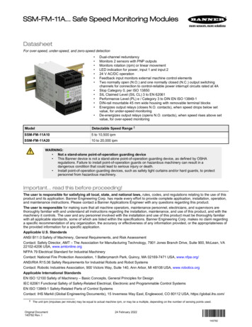
SSM-FM-11A. Safe Speed Monitoring ModulesDatasheetFor over-speed, under-speed, and zero-speed detection Dual-channel redundancyMonitors 2 sensors with PNP outputsMonitors rotation (rpm) or linear movementLED indication for power, input 1 and input 224 V AC/DC operationFeedback input monitors external machine control elementsTwo normally open (N.O.) and one normally closed (N.C.) output switchingchannels for connection to control-reliable power interrupt circuits rated at 4AStop Category 0, per ISO 13850SIL Claimed Level (SIL CL) 3 to EN 62061Performance Level (PL) e / Category 3 to DIN EN ISO 13849-1DIN-rail mountable 45 mm wide housing with removable terminal blocksEnergizes output relays (closes N.O. contacts), when speed drops below setvalue, for under-speed monitoringDe-energizes output relays (opens N.O. contacts), when speed rises above setvalue, for over-speed monitoringModelDetectable Speed Range 1SSM-FM-11A105 to 10,500 ipmSSM-FM-11A2010 to 20,000 ipmWARNING: Not a stand-alone point-of-operation guarding device This Banner device is not a stand-alone point-of-operation guarding device, as defined by OSHAregulations. Failure to install point-of-operation guards on hazardous machinery can result in adangerous condition that could lead to serious injury or death. Install point-of-operation guarding devices, such as safety light curtains and/or hard guards, to protectpersonnel from hazardous machinery.Important. read this before proceeding!The user is responsible for satisfying all local, state, and national laws, rules, codes, and regulations relating to the use of thisproduct and its application. Banner Engineering Corp. has made every effort to provide complete application, installation, operation,and maintenance instructions. Please contact a Banner Applications Engineer with any questions regarding this product.The user is responsible for making sure that all machine operators, maintenance personnel, electricians, and supervisors arethoroughly familiar with and understand all instructions regarding the installation, maintenance, and use of this product, and with themachinery it controls. The user and any personnel involved with the installation and use of this product must be thoroughly familiarwith all applicable standards, some of which are listed within the specifications. Banner Engineering Corp. makes no claim regardinga specific recommendation of any organization, the accuracy or effectiveness of any information provided, or the appropriateness ofthe provided information for a specific application.Applicable U.S. StandardsANSI B11.0 Safety of Machinery, General Requirements, and Risk AssessmentContact: Safety Director, AMT – The Association for Manufacturing Technology, 7901 Jones Branch Drive, Suite 900, McLean, VA22102-4206 USA, www.amtonline.orgNFPA 79 Electrical Standard for Industrial MachineryContact: National Fire Protection Association, 1 Batterymarch Park, Quincy, MA 02169-7471 USA, www.nfpa.org/ANSI/RIA R15.06 Safety Requirements for Industrial Robots and Robot SystemsContact: Robotic Industries Association, 900 Victors Way, Suite 140, Ann Arbor, MI 48108 USA, www.robotics.orgApplicable International StandardsEN ISO 12100 Safety of Machinery – Basic Concepts, General Principles for DesignIEC 62061 Functional Safety of Safety-Related Electrical, Electronic and Programmable Control SystemsEN ISO 13849-1 Safety-Related Parts of Control SystemsContact: IHS Markit (Global Engineering Documents), 15 Inverness Way East, Englewood, CO 80112 USA, https://global.ihs.com/1The unit ipm (impulses per minute) may be equal to actual machine rpm, or may be a multiple, depending on the number of sensing points used.Original Document140782 Rev. I24 February 2022140782
SSM-FM-11A. Safe Speed Monitoring ModulesEU Declaration of Conformity (DoC)Banner Engineering Corp. herewith declares that these products are in conformity with the provisions of the listed directives and allessential health and safety requirements have been met. For the complete DoC, please go to 1Ax Safe Speed Monitoring Module2006/42/ECRepresentative in EU: Spiros Lachandidis, Managing Director, Banner Engineering BV. Address: Park Lane, Culliganlaan 2F, bus3,1831 Diegem, Belgium.OverviewThe SSM-FM-11A10 and SSM-FM-11A20 Safe Speed Monitoring Module ("the Module") can be used to monitor a rotating orlaterally moving device's stopping, starting, or speed. The Module requires signals from two independent sensors.As a "standstill" (under-speed) monitor, the Module is often used in combination with hard guarding, access doors, and safety gateswith solenoid-lock or -unlock safety switches. When the speed of the monitored device drops below the set switch point (where itsspeed is no longer considered dangerous), the Module closes its normally open (N.O.) safety output contacts, applying power to thesafety switch solenoid, releasing the switch lock and enabling the operator to open the safety gate.In over-speed monitor applications, the N.O. safety contacts are closed for operation (when the motor speed of the monitored deviceis below the set switch point). When the speed exceeds the set value, indicating a too-high (dangerous) speed, the safety outputcontacts open.IndicatorsStandstill / Under-speedMonitoring ApplicationsOver-speed MonitoringApplications1. Power ON(green) whenPower is appliedPower is applied2. Safety outputchannel 1 ON(green) whenStandstill signal detected on No over-speed detected onInput Channel 1Input Channel 12. Safety outputchannel 2 ON(green ) whenStandstill signal detected on No over-speed detected onInput Channel 2Input Channel 2Figure 1. SSM-FM-11A. features and terminal locations123Operation and RequirementsThe Module is redundant and self-checking. It requires digital input signals from two independent sensors (for example, proximityswitches) to monitor for either standstill (under-speed) or over-speed conditions.The input channels are factory pre-adjusted for simultaneity, and a simultaneity potentiometer (behind the Module front cover) isavailable to further synchronize the input channel timing. Two banks of DIP switches are also located behind the front cover, for thepurpose of selecting the switch point range; a second potentiometer is used to fine-tune the switch point setting. See Figure 7 onpage 6.2www.bannerengineering.com - Tel: 1 888 373 6767P/N 140782 Rev. I
SSM-FM-11A. Safe Speed Monitoring ModulesFigure 2. Functional DiagramMotor ONOverspeedMotor OFFMotor ONOverspeed DetectionMotor StandstillMotor StandstillMotor ONStopMotor ONStopStopMotor StandstillSupply ONStandstill DetectionMotor ONInput Sensor Requirements. Both sensors must have 24 V PNPoutputs. The Module continually monitors the power supply current toeach sensor. The minimum acceptable sensor current is 3 mA (withthe sensor PNP output in either the ON or OFF state). The Module willdetect if any sensor power supply wire (S1 , S1-, S2 , S2-) is broken.A broken power supply wire always results in an OFF condition. If the safety outputs are closed (on) when a sensor wirebreaks or is disconnected, the related internal relay turns offand the safety outputs open, signaling "No Standstill" and/or"Over-speed." If the safety outputs are open (off) when a sensor wire breaksor is disconnected, they cannot close (again signaling "NoStandstill" and/or "Over-speed") until the sensor connection isfixed.Sensor Mounting Requirements: For safe and reliable operation, thetwo input sensors must be mounted so that they are vibration-free,their signals are received simultaneously, and they don't influenceeach other.A1/A2 24V0VMotorSpeedS1sS2s13-1423-24tRes t dst dst doS2s: Output signal from sensor Bt ds: Response after standstill/underspeeddetectiont Res : Power-up delayt do: Response after overspeed detectionS1s: Output signal from sensor AMechanical InstallationThe SSM-FM-11Ax SSM Module must be installed inside an enclosure.It is not designed for exposed wiring. It is the user’s responsibility to house the SSM-FM-11Ax SSM Module in an enclosure withNEMA 3 (IEC IP54) rating, or better. The SSM-FM-11Ax SSM Module mounts directly to standard 35 mm DIN rail.Heat Dissipation Considerations: For reliable operation, ensure that the operating specifications are not exceeded. The enclosuremust provide adequate heat dissipation, so that the air closely surrounding the SSM-FM-11Ax SSM Module does not exceed themaximum operating temperature stated in the Specifications. Methods to reduce heat build-up include venting, forced airflow (forexample, exhaust fans), adequate enclosure exterior surface area, and spacing between modules and other sources of heat.Electrical InstallationIt is not possible to give exact wiring instructions for a Safety Module that interfaces to a multitude of machine control configurations.The following guidelines are general in nature.The Safety Module has no delay function. Its output relay contacts open within the time frame determined by the formula shown inthe Configuration section. This classifies the Safety Module as functional stop "Category 0", as defined by NFPA 79 and IEC/EN60204-1.Input Sensor ConnectionsThe Module provides 24 V DC and 0 V to power the sensors through S1 /S1- and S2 /S2-. The sensor output signals areconnected to terminals S1s and S2s.Periodic Checksthe safety function must be triggered during commissioning and, at least, once every 30 days (or at a frequency determined by a riskassessment).Reset and Startup ConditionsThe Module works only in automatic reset mode. In order for the Module to switch to RUN mode for normal operation, the Y1 - Y2feedback input must be closed during power-up.The Module typically requires two to three seconds after power On to evaluate the signals from the two sensors and to decide if thenumber of incoming signals/pulses is above or below the set switch point value. After three seconds, if the Module detects a numberof pulses per minute below the set value, the relays energize and the N. O. safety output contacts close, indicating a standstillcondition. If the machine being monitored and the Module are powered up at the same time, the machine has only three seconds tocome up to speed, or the Module detects a standstill condition. If the machine requires more than three seconds, power up themachine first, then the Module, after the appropriate delay.When each of the internal relays is energized, its corresponding LED turns On green. Both relay outputs activate only if both inputsreach the enabling conditions within approximately two seconds. If the signals are not received within two seconds, for example,because of a defective sensor or because the channels did not switch simultaneously, the output contacts will not close, and powerto the Module must be cycled.P/N 140782 Rev. Iwww.bannerengineering.com - Tel: 1 888 373 67673
SSM-FM-11A. Safe Speed Monitoring ModulesFigure 3. Typical hookup to two sensorsFigure 4. Typical hookup to one sensor0V24V ac/dcA1SSM-FM-11A10orSSM-FM-11A20A2Sensor 1 24VMSC1PNPSignalOutS1s0VS1-MSCMonitorContactsor JumperY2PNPSignalOutS2s0VS2-See External DeviceMonitoringMSC1S1 nitorContactsor JumperSee External DeviceMonitoringS2sS2-4 A max.4 A max.13A2 24V0VS2 SSM-FM-11A10orSSM-FM-11A20SensorMSC2Sensor 2 24V0VA1Y1S1 24V ac/dc131423243132Suited up to SIL3, Performance Level e, Cat. 3K1AK2AK1BK2BK1CK2C142432Suited up to SIL2, Performance Level c, Cat. 2 (to achieve CAT. 2 thesafety function has to be tested on a regular basis)Connection to the Machine to be ControlledThe machine wiring diagram shows a generic connection of the Safety Module's redundant output circuits to the Machine PrimaryControl Elements MPCE1 and MPCE2. A Machine Primary Control Element is an electrically powered device, external to theInterface Module, which stops the machinery being controlled by immediately removing electrical power from the machine and (whennecessary) by applying braking to dangerous motion.4www.bannerengineering.com - Tel: 1 888 373 6767P/N 140782 Rev. I
SSM-FM-11A. Safe Speed Monitoring ModulesFigure 5. Machine connection with an interlocked guard with guard locking and another safety module24V or 1 24VS1 Y1PNPSignalOutS1sY20VS1-Request toEnter (2)E10VES-FA-9AA24Vac/dcReset(1)MPCE1 MPCE2(6)0VA1A2S33S34 n.c.S11Sensor 2 24VS2s0VS2-StartFunction(7)S22S12Unlock (3)4A max.24V ac/dcMachineControlCircuitsS21S2 PNPSignalOut13K1AK2A(5)14OK to 0VMPCE124MPCE2(5)3334MPCE1 MPCE2MStandard connection, suited up to SIL3, Performance Level e, Cat. 31. Safety Module ES-FA-9AA is configured for manual reset. See data sheet p/n 60606 for complete information. Other SafetyModules can be used. Call Banner Engineering with all questions.2. After the guard has been closed, the Safety Module has been reset, and the machine control has started the motor, theRequest to Enter button can be pushed to interrupt the cycle.3. The machine control and the SSM Safe-Speed Monitoring Module enable the Unlock button and illuminate the OK to Openlight.4. The signal from the Unlock button energizes the solenoid locking mechanism of the locking style safety switch, allowing theguard to be opened. It is recommended to locate the Unlock button near the associated guard. The solenoid contactprevents the reset of the ES-FA-9AA Safety Module until the guard is locked.5. Arc Suppressor, see Warning, "Properly install arc or transient suppressors".6. See the External Device Monitoring section and the Warning, "Interfacing MPCEs".7. Not all feedback or monitoring functions of the machine interface are shown.WARNING: Interfacing MPCEs Failure to follow these instructions could result in serious injury or death. Do not wire any intermediate device(s) (PLC, PES, PC), between the Safety Module outputs and theMachine Primary Control Elements (MPCE1 to MPCE3) it switches in such a manner that in the event ofa failure there is the loss of the safety stop command, OR in such a manner that the safety function canbe suspended, overridden, or defeated, unless accomplished with the same or greater degree of safety. Whenever forced-guided, mechanically linked relays are added as intermediate switching devices, anormally closed forced-guided monitor contact from each relay must be added to the series feedbackloop between Interface Module terminals Y1 and Y2.WARNING: Properly install arc or transient suppressors Failure to follow these instructions could result in serious injury or death. Install any suppressors as shown across the coils of the machine primary control elements. Do notinstall suppressors directly across the output contacts of the safety or interface module. In such aconfiguration, it is possible for suppressors to fail as a short circuit.P/N 140782 Rev. Iwww.bannerengineering.com - Tel: 1 888 373 67675
SSM-FM-11A. Safe Speed Monitoring ModulesWARNING: Risk of electric shock Use extreme caution to avoid electrical shock. Serious injury or death could result. Always disconnect power from the safety system (for example, device, module, interfacing, etc.),guarded machine, and/or the machine being controlled before making any connections or replacing anycomponent. Lockout/tagout procedures might be required. Refer to OSHA 29CFR1910.147, ANSIZ244-1, or the applicable standard for controlling hazardous energy. Make no more connections to the device or system than are described in this manual. Electricalinstallation and wiring must be made by a Qualified Person 2 and must comply with the applicableelectrical standards and wiring codes, such as the NEC (National Electrical Code), NFPA 79, or IEC60204-1, and all applicable local standards and codes.External Device MonitoringTo satisfy the requirements of Control Reliability (OSHA and ANSI), Category 3 and 4 of ISO 13849-1, the Machine Primary ControlElements (MPCEs) must each offer a normally closed, forced-guided (mechanically linked) monitor contact. Connect one normallyclosed monitor contact from each Machine Primary Control Element as shown in the appropriate hookup drawing.In operation, if one of the switching contacts of either MPCE fails in the energized condition, the associated monitor contact willremain open. Therefore, it will not be possible to reset the Primary Safety Device. If no MPCE-monitor contacts are monitored, it isthe user's responsibility to ensure that any single failure will not result in a hazardous condition and will prevent a successivemachine cycle.Overvoltage Category II and III Installations (EN 50178 and IEC 60664-1)The Safety Module is rated for Overvoltage Category III when voltages of 1 V to 150 V AC/DC are applied to the output relaycontacts. It is rated for Overvoltage Category II when voltages of 151 V to 250 V AC/DC are applied to the output relay contacts andno additional precautions are taken to attenuate possible overvoltage situations in the supply voltage. The Module can be used in anOvervoltage Category III environment (with voltages of 151 V to 250 V AC/DC) if care is taken either to reduce the level of electricaldisturbances seen by the Module to Overvoltage Category II levels by installing surge suppressor devices (for example, arcsuppressors), or to install extra external insulation in order to isolate both the Safety Module and the user from the higher voltagelevels of a Category III environment.For Overvoltage Category III installations with output contact voltage 151 V to 250 V AC/DC applied to the outputcontact(s): the Safety Module may be used under the conditions of a higher overvoltage category where appropriate overvoltagereduction is provided. Appropriate methods include: An overvoltage protective device A transformer with isolated windings A distribution system with a multiplicity of branch circuits (capable of diverting energy of surges) A capacitance capable of absorbing energy of surges A resistance or similar damping device capable of dissipating the energy of surgesWhen switching inductive AC loads, it is good practice to install appropriately-sized arc suppressors to protect the Safety Moduleoutputs. However, if arc suppressors are used, they must be installed across the load being switched (for example, across the coilsof external safety relays), and never across the Safety Module's output contacts (see Warning, "Properly install arc or transientsuppressors").Auxiliary Monitor ContactThe action of the auxiliary monitor contact, terminals 31-32, inversely "follows" the action of the safety outputs. The 31-32 auxiliarymonitor contact is to be used only for control functions that are NOT safety-related. A typical use is to communicate the status of theSafety Module output to a programmable logic controller (PLC).ConfigurationFigure 6. Removing the front cover1. DIP switch bank AFigure 7. Module adjustments2. DIP switch bank B3. Simultaneity adjustmentpotentiometer1Frontplate4. Fine-tune potentiometer23426A person who, by possession of a recognized degree or certificate of professional training, or who, by extensive knowledge, training and experience, hassuccessfully demonstrated the ability to solve problems relating to the subject matter and work.www.bannerengineering.com - Tel: 1 888 373 6767P/N 140782 Rev. I
SSM-FM-11A. Safe Speed Monitoring ModulesUse DIP switch banks A and B together to set the ranges. For example, to select the first range setting, set DIP switch 1 in bank Aand in bank B to OFF, set DIP switch 2 in bank A and bank B to OFF.Range SettingsModel SSM- 10Model SSM- 205–40 ipm1,200–10,500DIP Switch Banks A and B1210–80 ONOFF35–340 ipm80–650 ipmONONAdjusting the Switch Point ValueThe Module's four impulse-per-minute (ipm) ranges are selected via redundant pairs of DIP switches, as shown in the table. Toaccess the DIP switches, insert a small flat-blade screwdriver in the slot behind the Module's front panel, and pry the front panel off.To adjust the switch point to any value, first select the range via the DIP switches. Then select the value within that range via thefine-tuning potentiometer, using either of two methods.Note: Operate the DIP switches when power is disconnected from the device.Approximate MethodThe mechanical range of the potentiometer is 270 . Because the potentiometer is linear, set the approximate values as in thefollowing example: Desired switching point: 1,400 ipm Selected range: 300 to 2,700 ipm Potentiometer range delta: 2,700 ipm minus 300 ipm 2,400 ipmWith the potentiometer dial all the way to the left (counterclockwise), the switch point is at 300 ipm. To increase the setting to 1,400ipm, 1,100 ipm (1,400 minus 300 1,100 ipm) must be added:[270 degrees 2,400 ipm (total range)] x 1,100 ipm 123.75 degreesStarting from the left, turn the potentiometer dial 123.75 clockwise. The middle position of the potentiometer is 135 (or 1,200 ipm),so the setting is just a few degrees right from the middle position. This method provides only an approximate value.More Precise MethodMeasure the motor speed, including the speeds to be detected as over-speed, under-speed or zero speed (standstill), using an rpmmeter.Adjusting SimultaneityThe input channels are factory pre-adjusted; use the simultaneity potentiometer (behind the Module's front cover) to furthersynchronize the input channel timing.1. Start the motor.The safety output contacts should open and indicators should turn off, as soon as the motor speed passes the switch point.2. Stop the motor.After the motor speed drops below the switch point value and after the selected delay time, the safety output contacts shouldclose and indicators should turn on.3. If only one of the two channels detects the low-speed condition, restart the motor and turn the simultaneity potentiometer afew degrees clockwise (or counterclockwise, depending on which of the two channels switched first) to adjust thesimultaneity. Repeat this procedure until both channels detect standstill and turn OFF both internal relays simultaneously.P/N 140782 Rev. Iwww.bannerengineering.com - Tel: 1 888 373 67677
SSM-FM-11A. Safe Speed Monitoring ModulesLinear or Rotational MovementThe Module can monitor either linear or rotational motion because it looks only for pulses on its two inputs.Linear Motion Applications (Monitoring the Speed of a Conveyor)Figure 8. Linear Motion DetectionConveyor (top view)Speed 1 meter per secondReflectorsSensor11 meterSensor2Conveyor (side view)Module should monitor conveyor for max. speed of 1 meter/second.Sensing points per meter pulses per meter: 1 per 0.25 meter 4 per meterMax. speed: 1 meter/second 60 meters/minuteNumber of pulses per minute at a speed in meters per minute: sensing points/meter meters/minuteFor this example, the number of pulses 4 pulses/meter 60 meters/minute 240 pulses/minute.To detect a speed greater than 1 meter/second, the switching point must be set slightly higher than 240 ipm; for 4 sensing points: 4pulses per meter.Rotational Motion ApplicationsDepending on the number of sensing points at the motor, the ipm (impulses per minute) can be a multiple of the motor rpm. Use thefollowing formula to calculate the number of impulses per minute the Module will see from the two sensor outputs: rpm x number ofsensing points per sensor ipmIf each sensor sees one sensing point per motor turn, then rpm ipm: At 1000 rpm with 1 sensing point per turn per sensor: 1000 x 1 1000 ipm At 1000 rpm with 2 sensing points per turn per sensor: 1000 x 2 2000 ipmBecause more sensing points per sensor are interpreted by the Module as a higher rpm, the more sensing points used, the closerthe switch point can be set to 0 rpm.Note: Both sensors must always sense their sensing points at the exact same time, so that the two Moduleinputs receive the pulses at the same time. If two sensing points are used per sensor, they must be offset by180 . If four sensing points are used, they must be offset by 90 of each other (see the following figures).8www.bannerengineering.com - Tel: 1 888 373 6767P/N 140782 Rev. I
SSM-FM-11A. Safe Speed Monitoring ModulesTwo sensing points at different distancesfrom the center of the disk. Each sensorsends one pulse per revolution to theModule (500 rpm 500 ipm).Two sensing points at the same distancefrom the center of the disk. Each sensorsends two pulses per revolution to theModule (500 rpm 500 x 2 1,000 ipm).Four sensing points at the same distancefrom the center of the disk. Each sensorsends four pulses per revolution to theModule (500 rpm 500 x 4 2,000 ipm).Standstill (Under-speed) Monitoring ApplicationsBecause the pulses that define the detected speed are created by sensors that monitor the moving or rotating part (work piece ortool), speed sensing is independent of the supply voltage of the monitored motor.The two input channels are factory pre-adjusted for reliable switching simultaneity of the sensor inputs. A channel fine-tuningpotentiometer inside the Module housing (behind the front cover) provides exact simultaneity.Figure 9. Under-speed TimingSet Switch Point Value(30 rpm)Motor Min.Speed (30 rpm)Set Switch Point Value (5 rpm)(Potentiometer)Safety OutputsSetupNormalOperationSpeedMotor Shuts OffAnd Comes to aStandstillDelay TimeA delay time occurs between the detection of the standstill condition and the closing of the safety output contacts; this delay time isbased on the Module's adjusted ipm (input pulses per minute) set value. Calculate the delay time as follows: (60 seconds adjustedipm value) minimum response time of 2.5 seconds output contact close delay (in seconds) after standstill detection .Example: ipm 15(60 seconds 15) minimum response time of 2.5 seconds 6.5 secondsIn this example, the safety output contacts closes 6.5 seconds after the standstill condition is detected. In standstill monitoringapplications, the safety output contacts are open when the motor speed is above the standstill switch point setting. When the speeddrops below that value, the output contacts close.Configuring for Under-speed DetectionUnder-speed detection is detecting a low speed anywhere within the set range of the Module. For this example, we are using 500ipm.1.2.3.4.5.6.7.8.9.Turn off the power to the Module.Using a small flat-blade screwdriver, pry open the Module's front plate.Using the four DIP switches, select a switching range of 300-2,700 or 80-650, depending on the model.Turn the fine-tune potentiometer counterclockwise to the 1 setting.Set the simultaneity potentiometer to the middle position (0).If sensors are not yet installed, install them now so that they can detect the rotation of the motor.Connect the sensors to the Module.Disconnect the wires from the Module safety output contacts 13-14 and 23-24.Connect power to the Module; the Motor should still be off.The Module's Power LED must come ON immediately. The safety output contacts (13-14 and 23-24) should close and theindicators should come on after no more than a 3-second time delay, indicating a standstill condition.10. Start the motor and run it at the speed you want to detect as under-speed (for this example, 500 ipm).11. The N.O. safety output contacts must open and the indicators must turn off.12. Slowly turn the fine-tuning potentiometer clockwise (1 or 2 degrees at a time), pausing to allow the Module its necessaryresponse time to detect under-speed. Continue to turn clockwise until both N.O. safety output contacts (13-14 and 23-24)close and the indicators turn on.13. Increase the motor speed again to normal operating speed.Both safety output contacts must open and the indicators must turn off.14. To test for the correct setting, slow the motor down below the set value (or turn the motor off).Both safety output contacts must close and the indicators must turn on again.P/N 140782 Rev. Iwww.bannerengineering.com - Tel: 1 888 373 67679
SSM-FM-11A. Safe Speed Monitoring Modules15. Wire the safety output contacts into your machine control circuit and verify that the system works according to therequirements.Use the simultaneity potentiometer to adjust simultaneity between the two input channels if only one of them detects the standstillsignal from its assigned sensor.Configuring for Zero Speed DetectionThese directions illustrate only one setup method, which may be not as accurate as using an rpm meter or an oscilloscope to set theswitching frequency to a precise value. This example should set the switch point very close to Standstill.1. Turn off the power to the Module and the machine.2. Pry open the Module's front plate with a small flat-blade screwdriver.3. Select the range with the slowest ipm values using the DIP switches (5-40 ipm range for model SSM-FM-11A10 and 10-80ipm range for model SSM-FM-11A20).4. Set the simultaneity potentiometer to the middle position (0).5. Use the fine-tuning potentiometer to set the switch point to the lowest possible value (fully counter-clockwise, to the 1setting).6. If the sensors are not yet installed, install them now so that they can detect the rotation of the motor.7. Connect the sensor outputs to the Module.8. Disconnect the wires from the Module safety output contacts 13-14 and 23-24.9. Connect power to the Module; the Motor should still be off.The Module Power LED must come on immediately. The safety output contacts (13-14 and 23-24) should close and theindicators should come on after no more than a 3-second time delay.10. Start the motor.The safety output contacts should open and the indicators should turn off, as soon as the motor speed passes the switchpoint for standstill.11. Stop the motor.After the motor speed drops below the minimum switch point value (less than 5 ipm or 10 ipm, depending on model) andaft
SSM-FM-11A20 10 to 20,000 ipm WARNING : Not a stand-alone point-of-operation guarding device This Banner device is not a stand-alone point-of-operation guarding device, as defined by OSHA regulations. Failure to install point-of-operation guards on hazardous machinery can result in a dangerous condition that could lead to serious injury .