Transcription
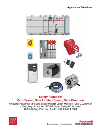
Application TechniqueSafety Function:Zero Speed, Safe Limited Speed, Safe DirectionProducts: PowerFlex 750 Safe Speed Monitor Option Module / TLS3-GD2 Switch/ GuardLogix Controller / POINT Guard Safety I/O ModulesSafety Rating: PLd, Cat. 3 to EN ISO 13849.1 2008
2Safety Function: Zero Speed, Safe Limited Speed, Safe DirectionImportant User InformationSolid state equipment has operational characteristics differing from those ofelectromechanical equipment. Safety Guidelines for the Application, Installation andMaintenance of Solid State Controls (publication SGI-1.1 available from your localRockwell Automation sales office or online athttp://literature.rockwellautomation.com) describes some important differencesbetween solid state equipment and hard-wired electromechanical devices. Becauseof this difference, and also because of the wide variety of uses for solid stateequipment, all persons responsible for applying this equipment must satisfythemselves that each intended application of this equipment is acceptable.In no event will Rockwell Automation, Inc. be responsible or liable for indirect orconsequential damages resulting from the use or application of this equipment.The examples and diagrams in this manual are included solely for illustrativepurposes. Because of the many variables and requirements associated with anyparticular installation, Rockwell Automation, Inc. cannot assume responsibility orliability for actual use based on the examples and diagrams.No patent liability is assumed by Rockwell Automation, Inc. with respect to use ofinformation, circuits, equipment, or software described in this manual.Reproduction of the contents of this manual, in whole or in part, without writtenpermission of Rockwell Automation, Inc., is prohibited.Throughout this manual, when necessary, we use notes to make you aware of safetyconsiderations.WARNING: Identifies information about practices orcircumstances that can cause an explosion in a hazardousenvironment, which may lead to personal injury or death,property damage, or economic loss.IMPORTANTIdentifies information that is critical for successful applicationand understanding of the product.ATTENTION: Identifies information about practices orcircumstances that can lead to personal injury or death,property damage, or economic loss. Attentions help youidentify a hazard, avoid a hazard, and recognize theconsequence.SHOCK HAZARD: Labels may be on or inside theequipment, for example, a drive or motor, to alert people thatdangerous voltage may be present.BURN HAZARD: Labels may be on or inside the equipment,for example, a drive or motor, to alert people that surfacesmay reach dangerous temperatures.Rockwell Automation Publication SAFETY-AT027D-EN-E – March 2013
Safety Function: Zero Speed, Safe Limited Speed, Safe Direction3General Safety InformationContact Rockwell Automation to find out more about our safety risk assessmentservices.IMPORTANTThis application example is for advanced users andassumes that you are trained and experienced in safetysystem requirements.ATTENTION: A risk assessment should be performed tomake sure all task and hazard combinations have beenidentified and addressed. The risk assessment may requireadditional circuitry to reduce the risk to a tolerable level.Safety circuits must take into consideration safety distancecalculations that are not part of the scope of this document.Table of ContentsIntroduction . 4Safety Function Realization: Risk Assessment . 5Safety Function . 5Safety Function Requirements . 6Functional Safety Description . 6Bill of Material . 7Setup and Wiring . 8Configuration . 10Programming . 19Falling Edge Reset. 21Calculation of the Performance Level. 21Verification and Validation Plan. 25Additional Resources . 33Rockwell Automation Publication SAFETY-AT027D-EN-E – March 2013
4Safety Function: Zero Speed, Safe Limited Speed, Safe DirectionIntroductionThis Safety Function application note explains how to wire, configure, and program aCompact GuardLogix controller and POINT Guard I/O module to interface to aPowerFlex 750 Safe Speed Monitor Option (-S1) module to perform Safe Speedfunctions. It is important to note that the safe speed module actually performs theZero Speed, Safe Limited Speed, and Safe Direction safety functions described inthis application note. The GuardLogix safety controller simply requests when theZero Speed and Safe Limited Speed (SLS) safety functions should be performed.For example, when the SLS keyswitch is rotated, the GuardLogix outputs wired tothe PowerFlex 755 SLS inputs are energized to request Safe Limited Speed. Notethat Safe Direction is configured in the safe speed module and is always beingmonitored. The GuardLogix controller has no interaction with the Safe Directionsafety function.The actuators for the safety functions are the Safe Torque Off (STO) channelsembedded within the safe speed module. If the PowerFlex 755 STO inputs are deenergized, the motor controlled by the PowerFlex 755 drive will coast to a stop.This example uses a Compact GuardLogix controller, but is applicable to anyGuardLogix controller.This example assumes the use of two diverse incremental encoders; one 845H andone 845T that are wired into the PowerFlex 750 Universal Feedback Option moduleand monitored by the safe speed module. The default MTTFd of 10 years, from ISO13849, is used. A Diagnostic Coverage of 99% will be obtained from the SISTEMALibrary of DC Measures. The DC is based on redundancy (two encoders), diversity(two types of encoders), diagnostics (cross monitoring between encoder signals),and individual power supplies for each encoder.The SISTEMA calculations shown later in this document would have to berecalculated if different products are used.Rockwell Automation Publication SAFETY-AT027D-EN-E – March 2013
Safety Function: Zero Speed, Safe Limited Speed, Safe Direction5Safety Function Realization: Risk AssessmentThe required performance level is the result of a risk assessment and refers to theamount of the risk reduction to be carried out by the safety-related parts of thecontrol system. Part of the risk reduction process is to determine the safety functionsof the machine. For the purposes of this document, the assumed requiredperformance level is Category 3, Performance Level d (Cat. 3, PLd).From: Risk Assessment (ISO 12100)1. Identification of safety functions2. Specification of characteristics of each function3. Determination of required PL (PLr) for each safety functionTo: Realization and PL EvaluationSafety FunctionThe PowerFlex 750 Safe Speed Monitor Option module is capable of performingmultiple safety functions simultaneously. In this application note, the followingfunctions are used:1. Safe DirectionWhen the safe speed module is configured to monitor the safe direction, a shutdownoccurs if the motor attempts to rotate in the dangerous direction.2. Safe Limited SpeedWhen Safe Limited Speed has been requested, the safe speed module initiates ashutdown, if the motor exceeds a pre-determined speed (the Safe Max Speed).When at or below the Safe Limited Speed, the door control logic is set to Unlock.You must perform a risk assessment to determine the safe maximum speed for theaxis.3. Standstill (Zero) SpeedWhen configured for Safe Stop, the safe speed module initiates a safe stop upondeactivation of the SS In inputs. Standstill Speed is used to declare motion asstopped. The system is at standstill when the speed detected is less than or equal tothe configured Standstill Speed. When standstill has been reached, door control logicis set to Unlock. Standstill Position Tolerance defines the position limit in encoderunits that is tolerated after standstill has been reached. If the position changes bymore than the amount specified by the Standstill Position Tolerance, after standstillRockwell Automation Publication SAFETY-AT027D-EN-E – March 2013
6Safety Function: Zero Speed, Safe Limited Speed, Safe Directionhas been reached and the door is unlocked, a fault occurs and the system enters thesafe state.Safety Function RequirementsLimiting and monitoring the speed of a motor to make sure hazardous motion doesnot exceed a predetermined limit. The safe speed limit must be established such thatthe operator can avoid the hazardous motion. Monitoring the direction of the motorguards against hazardous motion. The system monitors for Zero (Standstill) Speedso that the door remains closed and locked until hazardous motion is stopped. Atsuch time, the safe speed module unlocks the door by applying power to the guardlock. While the door is open, the system is monitored to prevent an unexpected startup. When the door is closed, hazardous motion and power to the motor does notresume until a secondary action (start button depressed) occurs.Faults at the variable speed drive, door interlock switch, encoder, wiring terminals orsafety controller will be detected before the next safety demand.The safety function meets the requirements for Category 3, Performance Level d(Cat. 3, PLd), per ISO 13849-1, and control reliable operation per ANSI B11.19.Functional Safety DescriptionIn this example, Safe Limited Speed is requested by placing a demand on a safetyinput interlock. After a user-configured delay (3 seconds in this example) to reach thesafe speed, the PowerFlex 750 Safe Speed Monitor Option module beginsmonitoring the speed and makes sure that the safe speed is not exceeded. If themotor speed is below the configured safe limited speed, the gate is unlocked to allowoperator entry into the hazardous area. If the motor speed exceeds the safe speedwhile the gate is unlocked, then the safe speed module drops out the Safe TorqueOff (STO) and the motor coasts to a stop.If a demand is placed on the Emergency Stop, the safe speed module drops out theSTO and the motor coasts to a stop. When Zero Speed is reached, the gate unlocks.The TLS3-GD2 channels are wired to the safe speed module in the PowerFlex 750drive. One channel pair is the lock monitoring contacts and the other is the doormonitoring contacts. The gate solenoid is wired to the safe speed module as well.The Safe Stop button, Reset button, and Safe Limited Request keyswitch are wiredto the POINT Guard input module. Outputs from the POINT Guard output module arewired directly to inputs on the safe speed module. These hardwired signals includethe Safe Stop, Safe Limited Speed Request, and a reset signal. The I/O module isconnected via CIP Safety over an EtherNet/IP network to the safety controller (SC1).The safety code in SC1 monitors the status of the Emergency Stop and SLS safetyinputs using the pre-certified safety instruction Dual Channel Input Stop (DCS).When all safety input interlocks are satisfied, no faults are detected, and the resetpush button is pressed, a second certified function block called ConfigurableRedundant Output (CROUT) controls and monitors feedback for the Safe Stop signalto the PowerFlex 750 drive.Rockwell Automation Publication SAFETY-AT027D-EN-E – March 2013
Safety Function: Zero Speed, Safe Limited Speed, Safe DirectionBill of MaterialThis application uses these products.Cat. No.DescriptionQuantity440G-T27181TLS3-GD2 Power to Release Safety InterlockSwitch1800FM-G611MX10800F Reset Push Button - metal, guarded, blue,R, metal latch mount, 1 N.O. contact(s),standard2800FM-KM22XM022 position keyswitch; metal; maintained; rightkey removal; 2 N.C. contacts1800FP-MT44PX02800F non-illuminated mushroom operators,twist-to-release, 40 mm, round plastic (Type4/4X/13, IP66), red, 2 N.C. contacts1800F-15YE112800F Legend Plate, 60 mm round, English:EMERGENCY STOP, yellow with black legendtext11768-ENBTCompactLogix EtherNet/IP Bridge Module1Compact GuardLogix Processor,1768-L43S2.0 MB standard memory, 0.5 MB safetymemory1768-PA3Power Supply, 120/240 VAC input, 3.5 A @ 24VDC11769-ECRRight end cap/terminator11734-AENT24V DC ethernet adapter11734-TBModule base with removable IEC screwterminals41734-IB8SPOINT Guard Safety Input Module11734-OB8SPOINT Guard Safety Output Module11783-US05TStratix 2000 Unmanaged Ethernet Switch120G11RD2P1AA0NNNNNPowerFlex 750; 480V; 2.1A continuous outputrating120-750-S1PowerFlex 750 Safe Speed Monitor OptionModule120-750-UFB-1PowerFlex 750 Universal Feedback OptionModule1User specified845T/845H Incremental Encoders2Rockwell Automation Publication SAFETY-AT027D-EN-E – March 201317
8Safety Function: Zero Speed, Safe Limited Speed, Safe DirectionSetup and WiringFor detailed information on installing and wiring, refer to the publications listed in theAdditional Resources on the back cover.System OverviewThe PowerFlex 750 Safe Speed Monitor Option module monitors two door channelsand two lock channels of the TLS3-GD2. The 1734-IB8S module monitors the SafeStop and Safe Limited Request keyswitch.Both the safe speed module and the 1734-IB8S module can source the 24V DC forall these channels to dynamically test the signal wiring for shorts to 24V DC andchannel-to-channel shorts. If a fault occurs, either or both channels will be set LO,and the system reacts by dropping out the Safe Torque Off (STO). The systemresets only after the fault is cleared and the input is cycled.Shorts to 0V DC (and wire off) are seen as an open circuit by the safe speed moduleand 1734-IB8S module input and the system will react by dropping out the safetycontactors. If the inputs remain discrepant for longer than the discrepancy time, thenthe PowerFlex 755 drive safety or controller will declare a fault. The system resetsonly after the fault is cleared and the input is cycled.The gate solenoid is controlled by the safe speed module.From a Guardlogix controller perspective, Safe Stop (Zero Speed) is a pair of safetyoutputs wired to the Safe Stop inputs (S12/S22) on the safe speed module. If theSafe Stop inputs ever go LO, a shutdown occurs and the motor coasts to a stop. TheGuardLogix controller gets feedback for Safe Stop by using one of the cascading SSoutputs (S34/S44) on the safe speed module. These safety outputs cannot restart ifthe feedback channel is not in the correct state. This feedback is optional. Becausethe redundant safety outputs are pulse tested, this is no different than wiring a Cat. 4light curtain to the SS inputs, an architecture that achieves Cat. 4 without feedback.From a Guardlogix controller perspective, the SLS safety function device is a pair ofsafety outputs wired to the SLS inputs (S52/S62) on the safe speed module. If theSLS inputs ever go LO, a SLS request is made to the PowerFlex 755 drive. TheGuardLogix controller gets feedback for SLS using one of the cascading SLS outputs(S68/S78) on the safe speed module. These safety outputs cannot restart if thefeedback channel is not in the correct state. This feedback is optional for the samereasons as stated above.The system has individual reset buttons for resetting faults and safety outputs. Ifeither of these resets is pressed, a signal is sent from a GuardLogix output to thereset input on the safe speed module (S34).The reset buttons and the feedback circuits are all wired to the 1734-IB8S module inthis example. This is not required for functional safety. These inputs could be wiredto a standard input module.Rockwell Automation Publication SAFETY-AT027D-EN-E – March 2013
Safety Function: Zero Speed, Safe Limited Speed, Safe Direction9Electrical SchematicSafety ResetFault ResetPowerFlex 755 drive standard wiring not shownE-StopKeyswitchPulse OutputsSS InputsSLS InputsEnable InputsSolenoidLock StatusDoor StatusPowerFlex 750 Safe Speed Monitor Option (-S1)SS OutputResetRockwell Automation Publication SAFETY-AT027D-EN-E – March 2013SLS Output
10Safety Function: Zero Speed, Safe Limited Speed, Safe DirectionConfigurationThe Compact GuardLogix controller is configured by using RSLogix 5000, version17 or later. You must create a new project and add the I/O modules. Then, configurethe I/O modules for the correct input and output types. A detailed description of eachstep is beyond the scope of this document. Knowledge of the RSLogix programmingenvironment is assumed.Configure the Controller and Add I/O ModulesFollow these steps:1. In RSLogix 5000 software, create a new project.2. In the Controller Organizer, add the 1768-ENBT module to the 1768 bus.Rockwell Automation Publication SAFETY-AT027D-EN-E – March 2013
Safety Function: Zero Speed, Safe Limited Speed, Safe Direction3. Select the 1768-ENBT module and click OK4. Name the module, type its IP address, and click OK.We used 192.168.1.8 for this application example. Yours may be different.5. Add the 1734-AENT adapter by right-clicking the 1768-ENBT module in theController Organizer and choosing New Module.Rockwell Automation Publication SAFETY-AT027D-EN-E – March 201311
12Safety Function: Zero Speed, Safe Limited Speed, Safe Direction6. Select the 1734-AENT adapter and click OK.7. Name the module, type its IP address, and click OK.We used 192.168.1.11 for this application example. Yours may be different.8. Click Change.Rockwell Automation Publication SAFETY-AT027D-EN-E – March 2013
Safety Function: Zero Speed, Safe Limited Speed, Safe Direction139. Set the Chassis Size as 3 for the 1734-AENT adapter and click OK.Chassis size is the number of modules that will be inserted in the chassis. The1734-AENT adapter is considered to be in slot 0, so for one input and one outputmodule, the chassis size is 3.10. In the Controller Organizer, right-click the 1734-AENT adapter and choose NewModule.Rockwell Automation Publication SAFETY-AT027D-EN-E – March 2013
14Safety Function: Zero Speed, Safe Limited Speed, Safe Direction11. Expand Safety, select the 1734-IB8S module, and click OK.12. In the New Module dialog box, name the device ‘IB8S’ and click Change.Rockwell Automation Publication SAFETY-AT027D-EN-E – March 2013
Safety Function: Zero Speed, Safe Limited Speed, Safe Direction1513. When the Module Definition dialog box opens, change the Output Data to ‘None’,verify the Input Status is Combined Status-Power’, and click OK.Setting the output data to ‘None’ means that you cannot use the Test Outputs asstandard outputs, which is appropriate in this example. This saves one controllerconnection because we are using only the input connection.14. Close the Module Properties dialog box by clicking OK.15. Repeat steps 10 14 to add the 1734-OB8S safety output module.a. Name the module OB8S.b. Choose slot 2.c. Select ‘Combined Status-Readback-Power’ for Input Status definitionRockwell Automation Publication SAFETY-AT027D-EN-E – March 2013
16Safety Function: Zero Speed, Safe Limited Speed, Safe DirectionConfigure the I/O ModulesFollow these steps to configure the POINT Guard I/O modules.1. In the Controller Organizer, right-click the 1734-IB8S module and chooseProperties.2. Click Test Output and configure the module as shown.T0 and T1 are used to pulse test the E-Stop and keyswitch.3. Click Input Configuration and configure the module as shown.Inputs 0/1 are the E-Stop channels. Recall that inputs 0/1 are being sourced fromtest outputs 0/1. Inputs 2/3 are the keyswitch channels. They are also beingsourced from test outputs 0/1. Single is used because the discrepancy timediagnostic is done in the Dual Channel Input Stop (DCS) safety instruction in thecontroller. Inputs 4/5 are the reset buttons. Inputs 6/7 are wired to the safe speedmodule for Safe Stop (SS) and Safe Limited Speed (SLS) feedback.4. Click OK.5. In the Controller Organizer, right-click the 1734-OB8S module and chooseProperties.Rockwell Automation Publication SAFETY-AT027D-EN-E – March 2013
Safety Function: Zero Speed, Safe Limited Speed, Safe Direction176. Click Output Configuration and configure the module as shown.Outputs 0/1 are controlling the Safe Stop inputs on the safe speed module.Outputs 4/5 are controlling the Safe Limited Speed inputs on the PowerFlex 755drive. All four of these outputs are configured for pulse testing. Output 7 is drivingthe reset signal on the safe speed module.7. Click OK.PowerFlex 750 Safe Speed Monitor Option Module ConfigurationThe parameters with a red arrow have been configured based on this examplearchitecture. Configure the remainder based on the risk assessment and applicationrequirements.General TabRockwell Automation Publication SAFETY-AT027D-EN-E – March 2013
18Safety Function: Zero Speed, Safe Limited Speed, Safe DirectionFeedback TabStop TabLimited Speed TabRockwell Automation Publication SAFETY-AT027D-EN-E – March 2013
Safety Function: Zero Speed, Safe Limited Speed, Safe Direction19Door Control TabProgrammingThe Dual Channel Input Stop (DCS) monitors dual-input safety devices whose mainfunction is to stop a machine safely, for example, an E-Stop, light curtain, or safetygate. In this example, one is being used to monitor an E-Stop button, and the other ismonitoring the Safe Limited Speed (SLS) keyswitch.The DCS instruction monitors dual-input channels for consistency (Equivalent –Active High) and detects and traps faults when the inconsistency is detected forlonger than the configured Discrepancy Time (ms).The automatic restart type lets the DCS output (O1) reset automatically after ademand. The manual action typically required for safety is provided in rung 1 to resetthe safety output enable.Input status typically represents the channel status of the two input channels. In thisexample, the ‘Combined Input Status’ bit goes LO if any of the eight input channelshas a fault.In this example, the DCS reset acts as a fault reset. Even when configured forautomatic restart, a reset is required to recover from a fault.The output (O1) of the DCS is used as a safety interlock in the seal-in rungs to drivethe SS OK and SLS OK tags. If the DCS output drops out, so does the seal-in and itremains off until a manual reset action is carried out.The Configurable Redundant Output (CROUT) instruction controls and monitorsredundant outputs. Essentially, this instruction verifies that feedback follows thesafety outputs appropriately. For the positive feedback used in this example: if theoutputs are HI, the feedback should be HI and vice versa. In this example, thefeedback has 500 ms to change to the proper state. Because only a single feedbackcircuit is being used, the feedback tag is used for both Feedback 1 and 2.The two output tags from the CROUT instruction are used to drive the safety outputson the 1734-OB8S module that are wired to the respective solid state inputs on thePowerFlex 750 Safe Speed Monitor Option module.Rockwell Automation Publication SAFETY-AT027D-EN-E – March 2013
20Safety Function: Zero Speed, Safe Limited Speed, Safe DirectionRockwell Automation Publication SAFETY-AT027D-EN-E – March 2013
Safety Function: Zero Speed, Safe Limited Speed, Safe Direction21Falling Edge ResetISO 13849-1 stipulates that instruction reset functions must occur on falling edgesignals. To comply with this requirement, a One Shot Falling (OSF) instruction isused on the reset rung. Then, the OSF instruction Output Bit tag is used as the resetbit for the Output Enable rungs.Calculation of the Performance LevelWhen configured correctly, these safety functions can achieve a safety rating of PLdaccording to EN ISO 13849.1 2008.The functional safety specifications of the project call for a minimum PerformanceLevel of PLd and a minimum structure of Cat. 3.A PFHd of less than 1.0E-06 for the overall safety function is one of the requirementsfor PLd.The measures against Common Cause Failure (CCF) are quantified using thescoring process outlined in Annex F of ISO 13849-1. For the purposes of the PLcalculation, the required score of 65 needed to fulfill the CCF requirement isconsidered to be met. The complete CCF scoring process must be performed whenimplementing this example.Calculations are based on one operation of the Safe Stop per hour; therefore 8760operations per year.The individual subsystem values are shown below.Zero SpeedRockwell Automation Publication SAFETY-AT027D-EN-E – March 2013
22Safety Function: Zero Speed, Safe Limited Speed, Safe DirectionSafe Limited SpeedSafe DirectionThe overall safety function value is shown below for each safety function.Zero SpeedRockwell Automation Publication SAFETY-AT027D-EN-E – March 2013
Safety Function: Zero Speed, Safe Limited Speed, Safe DirectionSafe Limited SpeedSafe DirectionRockwell Automation Publication SAFETY-AT027D-EN-E – March 201323
24Safety Function: Zero Speed, Safe Limited Speed, Safe DirectionThe safety functions can be modeled as shown in the following safety-related block diagram:Zero Speed800FPE-StopCh A1734-IB8S1768-L43S1734-OB8SSubsystem 2Subsystem 3Subsystem 4EncoderCh ATLS3-GD2Ch BEncoderCh A20-750-S1800FPE-StopCh BSubsystem 1TLS3-GD2Ch ASubsystem 5Subsystem 6Subsystem 7TLS3-GD2Ch AEncoderCh ATLS3-GD2Ch BEncoderCh BSafe Limited Speed800FMKeyswitchCh hCh BSubsystem 1Subsystem 2Subsystem 3Subsystem 4Subsystem 5Subsystem 6Safe DirectionEncoderCh A20-750-S1EncoderCh BSubsystem 1Subsystem 2Rockwell Automation Publication SAFETY-AT027D-EN-E – March 2013Subsystem 7
Safety Function: Zero Speed, Safe Limited Speed, Safe Direction25Verification and Validation PlanVerification and validation play an important role in the avoidance of faultsthroughout the safety system design and development process. ISO EN 13849-2sets the requirements for verification and validation by calling for a documented planto confirm that all of the safety functional requirements have been met.Verification is an analysis of the resulting safety control system. The PerformanceLevel (PL) of the safety control system is calculated to confirm it meets the RequiredPerformance Level (PLr) specified. The SISTEMA software tool is typically used toperform the calculations and assist with satisfying the requirements of ISO 13849-1.Validation is a functional test of the safety control system to demonstrate that itmeets the specified requirements of the safety function. The safety control system istested to confirm all of the safety related outputs respond appropriately to theircorresponding safety related inputs. The functional test should include normaloperating conditions in addition to potential fault inject of failure modes. A checklist istypically used to document the validation of the safety control system.Validation of software development is a process in which similar methodologies andtechniques that are used in hardware development are deployed. Faults, createdthrough poor software development processes and procedures, are systemic innature rather than faults associated with hardware, which are considered to berandom.Prior to validating the GuardLogix Safety System, confirm that the safety system andsafety application program has been designed in accordance with the GuardLogixSystem Safety reference manuals (publication 1756-RM093 for GuardLogix 5560and Compact GuardLogix, and publication 1756-RM099 for GuardLogix 5570controllers) and the GuardLogix Application Instruction Safety Reference Manual,publication 1756-RM095.Rockwell Automation Publication SAFETY-AT027D-EN-E – March 2013
26Safety Function: Zero Speed, Safe Limited Speed, Safe DirectionGuardLogix & PowerFlex 750 Safe Speed with Guard Locking Safety Function Verification and ValidationChecklistGeneral Machinery InformationMachine Name/Model NumberMachine Serial NumberCustomer NameTest DateTester Name(s)Schematic Drawing Number20-750-S1 Configuration SignatureIDController NameRSLogix 5000 Safety Signature IDSafety Network Number(s)RSLogix 5000 Software VersionSafety Control System ModulesGuardLogix System ModulesGuardLogix Safety Controller1768-L43SCompactLogix Ethernet Bridge1768-ENBTPOINT I/O Ethernet Adapter1734-AENTPOINT Guard I/O Input Modules1734-IB8SPOINT Guard I/O Output Modules1734-OB8SFirmware VersionRockwell Automation Publication SAFETY-AT027D-EN-E – March 2013
Safety Function: Zero Speed, Safe Limited Speed, Safe Direction27GuardLogix & PowerFlex 750 Safe Speed with Guard Locking Safety Function Verification and ValidationChecklist (continued)Safety System Configuration and Wiring VerificationTestStepVerification1Verify that the safe speed drive has been wired andconfigured in accordance with the Safe Speed MonitorOption Module for PowerFlex 750-Series AC DrivesSafety Reference Manual, publication 750-RM001.2Verify the safety system has been designed inaccordance with the GuardLogix System SafetyReference Manuals (publication 1756-RM093 forGuardLogix 5560 and Compact GuardLogix, publication1756-RM099 for GuardLogix 5570).3Verify the safety application program has been designedin accordance with the GuardLogix Application InstructionSafety Reference Manual, publicatio
Safety Function: Zero Speed, Safe Limited Speed, Safe Direction 5 Rockwell Automation Publication SAFETY-AT027D-EN-E – March 2013 Safety Function Realization: Risk Assessment The required performance level is the result of a risk assessment and refers to the amount of the risk reduc