Transcription
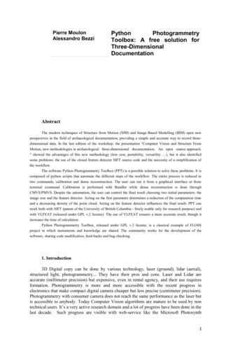
Pierre MoulonAlessandro BezziPythonPhotogrammetryToolbox: A free solution forThree-DimensionalDocumentationAbstractThe modern techniques of Structure from Motion (SfM) and Image-Based Modelling (IBM) open newperspectives in the field of archaeological documentation, providing a simple and accurate way to record threedimensional data. In the last edition of the workshop, the presentation “Computer Vision and Structure FromMotion, new methodologies in archaeological three-dimensional documentation. An open source approach.” showed the advantages of this new methodology (low cost, portability, versatility ), but it also identifiedsome problems: the use of the closed feature detector SIFT source code and the necessity of a simplification ofthe workflow.The software Python Photogrammetry Toolbox (PPT) is a possible solution to solve these problems. It iscomposed of python scripts that automate the different steps of the workflow. The entire process is reduced intwo commands, calibration and dense reconstruction. The user can run it from a graphical interface or fromterminal command. Calibration is performed with Bundler while dense reconstruction is done throughCMVS/PMVS. Despite the automation, the user can control the final result choosing two initial parameters: theimage size and the feature detector. Acting on the first parameter determines a reduction of the computation timeand a decreasing density of the point cloud. Acting on the feature detector influences the final result: PPT canwork both with SIFT (patent of the University of British Columbia - freely usable only for research purpose) andwith VLFEAT (released under GPL v.2 license). The use of VLFEAT ensures a more accurate result, though itincreases the time of calculation.Python Photogrammetry Toolbox, released under GPL v.3 license, is a classical example of FLOSSproject in which instruments and knowledge are shared. The community works for the development of thesoftware, sharing code modification, feed-backs and bug-checking.1. Introduction3D Digital copy can be done by various technology, laser (ground), lidar (aerial),structured light, photogrammetry. They have their pros and cons. Laser and Lidar areaccurate (millimeter precision) but expensive, even in rental agency, and their use requiresformation. Photogrammetry is more and more accessible with the recent progress inelectronics that make compact digital camera cheaper but less precise (centimeter precision).Photogrammetry with consumer camera does not reach the same performance as the laser butis accessible to anybody. Today Computer Vision algorithms are mature to be used by nontechnical users. It’s a very active research domain and a lot of progress have been done in thelast decade. Such progress are visible with web-service like the Microsoft Photosynth1
Project1.Our objective consist in providing a tool-chain in order to make 3D digital copy easy.This tool-chain should be Free, Open-source and Cross-Platform to be accessible withoutconstraint. Our pipeline draws largely from existing solution that have proven to befunctional and adequate.2. Related WorkThe reconstruction of a scene captured from different viewpoints by a set of 2Dimages is a computer vision problem that have been studied for decades. Such 3Dreconstructions are able to describe the structure (3D points) of the scene and theconfiguration (motion) of the camera for the registered pictures.The 3D reconstruction problem could be decomposed into three main steps:1. Correspondences between pairs of images are found and 3D configuration ofimage pairs are estimated (estimation of relative camera pose),2. The two-view geometries are fused in a common coordinates system(estimation of global camera pose),3. Having a complete camera calibration, a homogeneous dense model of thescene surfaces is computed using all images.While the two-view camera calibration is a well-studied problem, the multi-viewcamera calibration remains a challenging task. This multi-view calibration is crucial as it willdetermine the precision of the scene reconstruction and the quality of the resulting dense 3Dmodel.The most impressive progress in SfM and MVS make possible to compute a 3Drepresentation of a city from web images 2, with aerial or ground images. But only a few freeor open solution exists. Recent research gave birth to companies that have efficient productssuch as Pix4d3 and Acute3D4.A short history 3D reconstruction from pictures starts with project like Façade 5,Canoma6 and PhotoModeler7 that use corresponding points selected by the user in variouspictures to determine the 3D position of cameras and thus provide the user with an interfaceto model the pictured scene by hand . The process was long and required a lot of expertise.Progress in image matching and wide baseline matching allows now to determine thecorrespondences automatically thanks to contributions like SIFT 8 or SURF9.In recent years, a lot of commercial products and web services make 3Dreconstruction more accessible but computed 3D data are not always provided to the users.The main example is Photosynth. It only provides a 3D visualization service to travelthrough the set of photos but 3D data cannot be used for your own purpose. The web serviceuses the cloud as a storage and computational platform, so the pictures and computed datausage are not under your control. Some web services are free (ARC3D 10 or CMP SFMWebService11) but again they use a cloud for computation so there is no of the usage of the12http://photosynth.netAGARWAL et alii 2009FRAHM et alii 20103 http://www.pix4d.com/4 http://www.acute3d.com/5 http://ict.debevec.org/ debevec/Research/6 http://www.canoma.com/7 http://www.photomodeler.com/8 LOWE 20049 BAY et alii 200810 http://homes.esat.kuleuven.be/ visit3d/webservice/v2/11 http://ptak.felk.cvut.cz/sfmservice/2
data (pictures).Thanks to the emergence of OpenSource frameworks (Bundler 12, CMVS/PMVS13)that perform multi-view calibration and dense 3D point cloud computation, we aim todevelop a free and easy to use pipeline in order to make 3D digital copy easy. We providethe user a self-contained solution that gives him control on the whole data flow. As picturesare the property of the user we chose a user-side pipeline. The main drawback of ourapproach is that computation speed depends from user's computer. It could have somedrawbacks for large scenes or large images but a compromise between performance andquality can be made by reducing image size dynamically in the toolbox.3. 3D from pictures, the basisBuilding 3D “model” from pictures consists in recover 3D camera positions related topictures and 3D positions of particular content of the images. It is done by identifying similarcontent between N views and solve 3D geometry problems. User input consist of an imagecollection and camera parameters. The computed output is a set of 3D camera positions and3D points (fig. 1).3D from pictures is an active research domain that rely on Computer Vision and morespecifically, Image retrieval/matching, Structure from Motion (SfM) and Multiple ViewStereovision (MVS). Image matching finds common local sub-image between two pictures. Structure from Motion estimates the relative camera position from anchorpoints computed at the previous step. Multiple View Stereovision estimate a dense representation of the 3D model(Dense point cloud).3.1 Image MatchingImage matching identifies pictures that can be used to compute the relative orientationof 2 camera and thus to calibrate a network of images. This process of image matching isperformed in 3 steps:1. compute local content on each image(Feature and Descriptor computation, forinstance SIFT),2. find putative matches between two pictures (find the nearest descriptor in theother image of the pairs),3. check the geometry of the putative matches (Epipolar geometry).Once the image matching between all possible pair is performed, a geometric graph isbuilt (fig. 2). An edge is added if a geometric connection exists between two pictures.3.2 Camera Pose estimationCamera pose estimation finds the camera positions by solving the relative poseestimation problem. Relative pose estimation consists in estimating a rigid motion betweentwo cameras, a rotation R and a translation T (fig. 3). This relative geometry between two12 SNAVELY 200813 FURUKAWA 20103
views is faithfully described by an “Essential” matrix 14.This Essential 3 3 matrix relates corresponding points in stereo images assuming thatthe cameras satisfy the pinhole camera model. This E matrix could be computed from 8points with a linear method or with 5 points 15. The 5 points method is preferred because it isthe minimal case and it allows to add more constraint on the estimated matrix and so providemore accurate results. The image matching step is thus crucial: the more common points weget between pictures we will get, the more images we can estimate 3D positions accurately.The position of a camera can also be computed from correspondences between 3Dpoints and corresponding projections in the image plane. This 3D-2D correspondenceproblem is known as Resection (fig. 4). It consists in estimating Pi (rotation, translation andinternal parameters of the camera) with a ray constraint geometry. It finds the Piconfiguration that minimize the re-projection errors between the rays passing through opticalcamera center to 3D points and the 2d image plane coordinates. Once two cameras arerelated with an Essential matrix and 3D points X are build, we can add incrementally newcamera to the scene by using successive resection.Based on those computations (Essential, Resection) we can perform IncrementalStructure from Motion. It’s the algorithm that is implemented in the 3D calibration softwarewe use (Bundler).3.3 Incremental Structure from MotionBundler is one of the state-of-the-art implementation of incremental SfM. It takes asinput a image series and camera information (like focal values extracted from Exif jpg dataand CCD sensor size available on camera manufacturer website or dpreview.com).From an initial image network, Bundler chooses a pair of images, computes therelative pose with the Essential Matrix and try to add incrementally the remaining images inthe 3D scene by using successive resections. In order to avoid incremental error, bundleadjustments16 is used to refine non linearly the estimated camera parameters and 3D pointpositions, and thus reduce the error across computed data whose size is growing.This pseudo algorithm can be pictured as in figure 5:Input:image network of geometrically coherent pictures,internal camera parameters (Focal length, CCD sensor size). Output: camera position,sparse point cloud.Bundler suffers from some defaults. It's code is not very clean and sometimes the 3Dreconstruction fails due to drift error. But it have the advantage of being nearly the onlyOpen-Source viable solution over internet with such performance. Recent communityinitiative like the libmv project 17 is a prelude to a cleaner implementation of “Bundlerclones”. This bricks could be replaced in the tool-chain in a near future.3.4 Multiple View Stereovision14 http://en.wikipedia.org/wiki/Essential matrix15 NISTER 200416 http://en.wikipedia.org/wiki/Bundle adjustment17 http://code.google.com/p/libmv/4
Multiple View Stereovision (MVS) consists in mapping image pixel to 3D pointsfcposes, images point cloud. This dense representation can be a dense point cloud or a densemesh. In order to find a 3D position for each corresponding pixel of the image sequence,MVS uses multiple image to reduce ambiguities and estimate accurate content (fig. 6).One of the interesting state-of-the-art method is the Patch approach called PMVS(Patch MultiView Stereo) 18. It is based on a seed growing strategy. It finds correspondingpatches between images and locally expand the region by an iterative expansion and filteringsteps in order to remove bad correspondences (fig. 8). Such an approach finds additionalcorrespondences that were rejected or not found at the image matching phase step.Figure 9 shows benefit of using PMVS (empty 3D zones correspond to poorlytextured or too ambiguous image zones):4. The Python Photogrammetry ToolboxThe Python Photogrammetry Toolbox (PPT)19 implements a pipeline to perform 3Dreconstruction from a set of pictures. It design follows the classic reconstruction process. Ittakes pictures as input and performs automatically the 3D reconstruction for the images forwhich 3D registration is possible. PPT hides from the user the boring task of data conversionand files listing that are required to communicate through the various software componentsof the chain. Open-source software has been chosen to perform the intensive computationalparts of the reconstruction pipeline, Bundler for the camera pose estimation andCMVS/PMVS for the dense point cloud computation.Initially Bundler and CMVS/PMVS are provided with some shell scripts thatautomates launching tasks, but one of the main drawback of shell is that it is not crossplatform. It cannot be used under Windows. Compilation of those software are not managedthrough the same basic interface (Makefile on Linux and vcproj on Windows) and sorequires double maintenance for smooth compilation on both platform. Design choices inPPT make it cross-platform: it uses Python20 as a cross-platform script language to handle communication andsoftware launching operations. It handles all the tasks that are required for our purpose(directory listing, file listing, images conversion, Exif reading, Sqlite databasemanagement); it uses Cmake21 for the compilation configuration of the chosen Open-Software thatis available under the Open Source Photogrammetry code repository 22.PPT provides a tool-chain that is easier to maintain and use than the previousapproaches. It defines a clear pipeline to handle 3D reconstruction. This pipeline is designedas python module with a High Level API in order to be extensible in the future. It results in a3-level application: Interface, Python modules and Software.A graphic wrapper has been developed to hide the command-line calls that arerequired to use the chain through python modules. It provides a 2-step reconstructionworkflow.The multi-level application makes maintenance easier. Each bottom module can beupdated as long it respects the designed High Level API. It makes the interface easilyextensible. For example the python wrapper use a design pattern interface in order to havevarious feature detection/description algorithm for the image matching step (the user can use18 FURUKAWA 201019 Source code is accessible from http://code.google.com/p/osm-bundler/20 http://www.python.org/21 http://www.cmake.org/22 https://github.com/TheFrenchLeaf5
the David Lowe SIFT23 or the Open-source implementation VLFEAT24).Data workflow is organized in a temp directory created at the beginning of theprocess. All the required data to process the 3D reconstruction is located in this directory.Data is updated by the different element of the tool-chain and showed at the end to the uservia a directory pop-up. The main workflow is illustrated in figure 10. It’s interesting to take acloser look to the 2-step process workflow (RunBundler and RunCMVS) to better see the jobof the python scripts.RunBundler (fig. 11) performs the camera calibration step. It computes the 3Dcamera pose from a set of image with corresponding “camera model”/”CCD width size”embedded in an Sqlite database. In figure 11, orange coloured items (bottom squares) are thecreated files. We recognize image matching tools (sift, matchFull) and the 3D poseestimation software (Bundler).RunCMVS (fig. 12) takes as input the images collection, cameras poses and performthe dense 3D point cloud computation. Data conversion from Bundler format toCMVS/PMVS format is done by using Bundle2PMVS and RadialUndistort. Densecomputation is done by PMVS as well as CMVS, that is an optional process to divide theinput scene in many smaller instance that make the process of dense reconstruction faster.PPT-Gui (fig. 7) is the graphical interface to interact easily with the photogrammetrytoolbox25. The Gui part is powered by PyQt4 26, a multi-platform gui manager. Theinterface is designed in two different parts: a main window composed by numbered panelswhich allows the user to understand the steps to perform, and a terminal window in whichthe process is running. The GUI is deliberately simple and it is build for people who are notfamiliar with command-line scripts. The four panels lead the user to the end of the processthrough only two steps: Run Bundler (panel 1) and Run CMVS\PMVS (panel 2). RunningCMVS before PMVS is highly recommended, but not strictly necessary: there is also thepossibility to use directly PMVS (panel 3). Panel 4 provides a fast solution to integrate theSQL database with the CCD width (mm) of the camera, without using external software.5. ApplicationArchaeological field activity is mainly a working process which ends, in most cases,with the complete destruction of the site. Usually a ground layer is excavated to investigatethe underlying level. In the lack of particular expensive equipment (laserscanner, calibratedcamera) or software (photogrammetric applications), field documentation is composed bypictures (digital or films), manual drawings, total station measurements and bi-dimensionalphoto-mosaics. At best all the data are connected together inside a Geographical InformationSystem (GIS).The last years' progresses of Computer Vision open new perspectives, giving toeverybody the possibility to record three-dimensional data. The benefits of this technique aredifferent: it is a software-based technology in continuous developing (data analysed todaycould be processed in future ending in better results),it is well represented by Free and Open Source solutions,it needs only the equipment which is normally used in an excavation (digital cameraand total station),easily portable hardware components allow archaeologists to work under critical orextreme conditions (e.g. in high mountain, underwater or inside a cave),23 http://www.cs.ubc.ca/ lowe/keypoints/24 http://www.vlfeat.org/25 Source code is accessible from https://github.com/archeos/ppt-gui/26 http://wiki.python.org/moin/PyQt46
the flexibility of this technique facilitates the documentation of a wide range ofsituations.The next chapters introduce some examples of application in different scales: frommacro (layers, structure) to micro (finds).5.1. LayersNormally archaeological layers are documented using photomapping techniques, a bidimensional projection of reality which produce rectified images starting from zenithpictures and ground control points (GCP). Using the same instruments (digital camera andtotal station) it is possible to record also the morphology of the level (figg. 13-14). The dataacquisition is fast and simple: it consists exclusively in taking pictures of the area of interest(both horizontal surfaces and vertical sections) paying attention to include at least threemeasured marks, which will be used in data processing to georeference the final model. Thesame rules of the traditional photography are to be followed: centre the desired object in eachpicture, avoid extreme contrast shadow/sun, use a tripod in low-light condition.There are no limits around the number of images: it depends on the complexity of thesurface and on the power of the hardware (RAM) which will process the data.5.2. Architectonic StructureThis technique is particularly indicated for architectonic monuments (figg. 15-16). Inthis case the main difficulty is to cover the whole object with a good photo set, in order toavoid holes in the final mesh. Most of the time it is possible to solve logistical problemsrelated to the complexity of the structure, using specific hardware like telephoto lenses orremote sensing devices (UAV).5.3 Finds (artefacts and ecofacts)Archaeological finds can be documented “in situ”, taking pictures moving around theobject (fig. 17), or in laboratory using a turntable and a black background (fig. 18). In thislast case the position of the camera during data acquisition was fixed, but will be split inmore poses during data processing (fig. 19). Good results were reached taking a picture each10 degrees, 36 photos for a complete revolution of the object. It is possible to use macros toobtain model of a small artefact.5.4 3D-data recovering from old or historical photo setsOne the most interesting approaches of SfM is the ability to extract three-dimensionalinformation from old or even historical photographs taken by amateurs for other purposes.The critical point of this application is to reach the minimal number of images needed to startthe reconstruction process (3). It is much easier to find an appropriate photographicdocumentation since digital cameras have become a widespread phenomenon (figg. 20-21).If a monument in the present is not longer in his original conservation status or evencompletely destroyed (e.g. the Banyan Buddhas), Computer Vision is a valid method torecover the original morphology.7
6. ConclusionPython Photogrammetry Toolbox (PPT) is an user-friendly application to perform 3Ddigital copies of pictured scenes. It provides a low-cost, portable solution that opens a directaccess to Structure from Motion (SfM) and Image-Based Modelling (IBM) to every owner ofa consumer camera. It opens particularly interesting perspective in the field of archaeologicaldocumentation due to the fact that a reflex camera is much cheaper than a laser scanner. Apossible drawback of the current solution is that it uses a feature detector/descriptor forimage matching (SIFT algorithm) that is under Patent in the USA. A rewritten and optimizedversion of SIFT is included inside VLFeat (an Open and Portable Library of ComputerVision Algorithms, released under GPL v. 2). This can't completely solve the licenseproblem but most of the users are aware of those constraints.A direct comparison between SfM/IBM and hardware technology (laser scan) or otherphotogrammetric applications is certainly possible, but it is not the objective of this article.All these techniques are different in their approach, but they lead to similar results. Thechoice of one of these methods depends on various factors: environmental characteristics ofthe site, economic budget of the project and technical skills of the staff. Anyway SfM/IBM isable to satisfy some of the basic needs of a typical archaeological project: the reduction ofcosts related to equipment, a fast and simple data collection process and a low-interactiveand easy data processing. For these reasons SfM/IBM is a viable alternative to moreexpensive (laserscan) or more technically complex (stereo-photogrammetric restitution)methods. From an archaeological point of view, the final intent is to acquire threedimensional morphology of the layers that the excavation irreparably destroyed and to createa virtual copy of the archaeological record to allow continuous monitoring and furtheranalysis. The good results achieved in a such fast way can be used to extract 3D volume(voxel) of each stratigraphic level, applying free software like GRASS, Blender andParaView27.PPT is an open source solution, that make 3D reconstruction from images easier, inwhich user contribution will produce benefit for all the community. It is a example of howthe combination of FLOSS projects can contribute to scientific and methodological progress.The future implementation will consider multi-thread computation, performanceimprovement and functionality addition.AcknowledgementsThis work have been made possible due to many individual Open-Source initiative.We thanks particularly Noah Snavely for Bundler sources, Yasutaka Furukawa forCMVS/PMVS sources and Vladimir Elistratov for the osm-bundler initiative.BibliographyAGARWAL 2009S. Agarwal - N. Snavely - I. Simon - S. M. Seitz - R. Szeliski, Building Rome in a day, in ICCV 2009, 72-79.BAY 2008H. Bay – A. Ess - T. Tuytelaars – L. Van Gool, SURF: Speeded Up Robust Features, in CVIU 2008, 346-359.BEZZI 2006A. Bezzi – L. Bezzi – D. Francisci – R. Gietl, L'utilizzo di voxel in campo archeologico, in Geomatic Workbooks,6, 2006.FRAHM 2010J. -M. Frahm – P. Georgel - D. Gallup – T. Johnson – R. Raguram – C. Wu – Y.-H. Jen – E. Dunn - B. Clipp - S.27 Bezzi 2006.8
Lazebnik, Building Rome on a Cloudless Day, in ECCV 2010, 368-381.FURUKAWA 2010Y. Furukawa – B. Curless – S. M. Seitz – R. Szeliski. Towards Internet-scale multi-view stereo, in CVPR 2010,1434-1441.LOWE 2004D. G. Lowe, Distinctive image features from scale-invariant keypoints, in IJCV 2004, 91-110.NISTER 2004D. Nister, An Efficient Solution to the Five-Point Relative Pose Problem, in IEEE Trans. Pattern Anal. Mach.Intell. 2004, 756-777.SNAVELY 2008N. Snavely – S. M. Seitz – R. Szeliski. Modeling the World from Internet Photo Collections, in IJCV 2008, 189210.FiguresFig. 01: Structure from Motion/Image-Based Modeling's standard workflow.Fig. 02: Three steps of Image Matching and final geometric graph.Fig. 03: Essential matrix E.Fig. 04: Resection.Fig. 05: Bundler's workflow.Fig. 06: Multiple View Stereovision (MVS) allows to convert image pixel to 3Dpoints starting from camera poses, photos and an initial point cloud.Fig. 07: Python Photogrammetry Toolbox GUI.Fig. 08: Initial seed (left), patch expansion (middle) and problem parametrization(right).Fig. 09: Bundler result (calibration) on the left and PMVS result (dense point cloud)on the right.Fig. 10: Python Photogrammetry Toolbox pipeline.Fig. 11: RunBundler pipeline.Fig. 12: RunCMVS pipeline.Fig. 13: Mesh of an archaeological layer in Georgia (University of Innsbruck, Institutfuer Alte Geschichte und Altorientalistik, S. Heinsch and W. Kuntner).Fig. 14: Stratigraphy (both vertical and horizontal) of an archaeological trench(Soprintendenza per i beni archeologici del Friuli Venezia Giulia – M. Frassine).Fig. 15: Dense point clouds of the Mausoleum of Theodoric in Ravenna (University ofUdine – S. Marchi).Fig. 16: Inside the Mausoleum of Theodoric in Ravenna (University of Udine – S.Marchi).Fig. 17: Mesh of an ancient vase documented “in situ” (Soprintendenza per i beniarcheologici del Friuli Venezia Giulia – M. Frassine).Fig. 18: 3D model of a loom weight documented in laboratory (Soprintendenza per ibeni librari, archivistici e archeologici della Provincia Autonoma di Trento – N. Pisu).Fig. 19: Dense point clouds of a human skull (left) extracted from pictures taken by afix camera and “false” viewpoints (right). The object was rotating using a turntable(Soprintendenza per i beni librari, archivistici e archeologici della Provincia Autonoma diTrento – N. Pisu).Fig. 20: Sparse point clouds of a ancient vase obtained from pictures taken byamateurs for other purposes (University of Innsbruck, Institut fuer Alte Geschichte undAltorientalistik, S. Heinsch and W. Kuntner).Fig. 21: Morphology of a wall surface extracted from photos taken in 2005, threeyears before the release of Bundler 0.1 (Soprintendenza per i beni librari, archivistici e9
archeologici della Provincia Autonoma di Trento – N. Pisu).Affiliation Pierre MOULON IMAGINE/LIGM, University Paris Est & Mikros Imagehttp://imagine.enpc.fr http://mikrosimage.eupmo@mikrosimage.eu Alessandro BEZZI ArcTeam team.com10
11
12
Python Photogrammetry Toolbox: A free solution for Three-Dimensional Documentation Abstract The modern techniques of Structure from Motion (SfM) and Image-Based Modelling (IBM) open new perspectives in the field of archaeological documentation, providing a simple and accurate way to record three-dimensional data.