Transcription
Design for AdditiveManufacturing (DFAM)ME2110 – Austen Thien
Learning Objectives Obtain a broad understanding of Additive Manufacturing (AM) Distinguish between AM and Traditional Manufacturing Recognize when 3D printing is appropriate, and when anothermanufacturing method would be more appropriate Apply heuristics while making AM design decisions Recognize applications of AM parts in mechanism design
Additive Manufacturing “Additive manufacturing uses data computer-aided-design (CAD)software or 3D object scanners to direct hardware to depositmaterial, layer upon layer, in precise geometric shapes.” – GE Additive Additive manufacturing adds material to create an object Traditional manufacturing is subtractive manufacturing because you areremoving material – milling, carving, shaping, machining, etc Although the term "3D printing" and "rapid prototyping" is casuallyused to discuss additive manufacturing, it is actually a subset ofadditive manufacturing
Types of AM Selective Laser Sintering (SLS) “Powder bed” 3D printing Laser is used to fuse small particles of plastic, ceramic, glass, or metal Stereolithography (SLA) Uses photochemical processes to form polymers layer-by-layer Fused Deposition Modeling (FDM) or Fused Filament Fabrication (FFF) Nozzle extrudes molten material to form layers In the Invention Studio and IDEA Lab
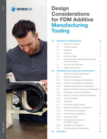
FDM A heated thermoplastic filament isextruded from a capillary die Part chamber is heated tominimize stresses and deformation Requires support structures Stratasys, Prusa, Ultimaker,Makerbot, RepRap etc
Benefits of AM Complexity of a part is independent of its costand manufacturability No tooling Internal features such as cooling channels Topology optimization for weight reduction anduniform stress distribution Parts can be easily customized or personalized Custom materials Assemblies can be directly produced, parts canbe interlinked Less waste (materials are used more efficiently)
Drawbacks to AM A complete digital model is needed Constrained by CAD capabilities Anisotropy Surface roughness, impact of build orientation Mechanical and thermal stresses meanthat support structures are needed duringproduction Support materials can become trapped in thepart
When to 3D Print Limited production run or just one custom part New part to interface with existing parts Repair broken or missing parts Part with complex 3D geometry Consolidating parts to print as an assembly
When Not to 3D Print Don’t 3D print 2-dimensional objects Think about other manufacturing methods that might be moreappropriate Common mistake: don’t 3D print boxes or similar items that couldmore easily be made by assembling 2D parts Consider other manufacturing methods if you are making manyidentical parts (injection molding?)
Design for Additive Manufacturing As you can tell, designing for additive manufacturing is considerablydifferent from designing for traditional manufacturing methods Heuristics: rules of thumb, methods/principles for making decisions,simplification to address a problem, “common sense”
Heuristics
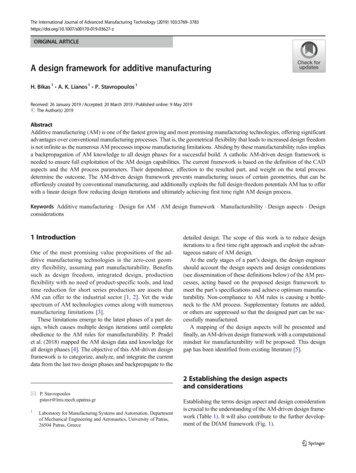
Overhang If there is an overhang on thepart, ensure that the angle issmaller than 45 If the angle of the overhang islarger than 45 , then supportstructure is required
Accessible Support If your part requires supportstructures that must beremoved, make sure they arenot trapped inside aninaccessible volume If support structures aretrapped, modify the partgeometry to ensure it can beremoved
Part Size If the part is larger than thebuild area in one direction,either reorient it, or split thepart into twoUnfavorableFavorable
Warping Thermal cycling in FDM 3D printing can lead to warping Degree of warping can be material dependent ABS is more susceptible to warping and thus needs a heated enclosure Build plate adhesion can mitigate part warping
Corners If the corners on the bottom ofthe part are warping, design thepart to have rounded (filleted)corners instead of sharp corners
Surfaces If the angle of a surface is not 0 or 90 , the surface will have astaircase effect Reducing layer height willimprove the surface roughnessof the part Redesign the part with faces thatare parallel and perpendicular tothe print bed
Surfaces As-built parts may not havefunctional surfaces due tostaircase effect and leftoversupport material SandingAs-builtSanded Higher grit yields smoothersurface Vapor Smoothing Acetone vapor causes partialmelting of plastic that blendstogether layer linesAs-builtVapor Smoothed
Feature Size Rule of thumb: features shouldbe 1.0 mm in thickness Nozzle size ranges from 0.4 –0.8mmLooks ok, right? Nozzle size determines minimumfeature accuracy Minimum feature thickness dependson printer specsWrong!
Infill Percentage Infill: Percent of material inside perimeter of part Reduces print time and material cost to achievecomparable strength Higher infill, stronger but more expensive part
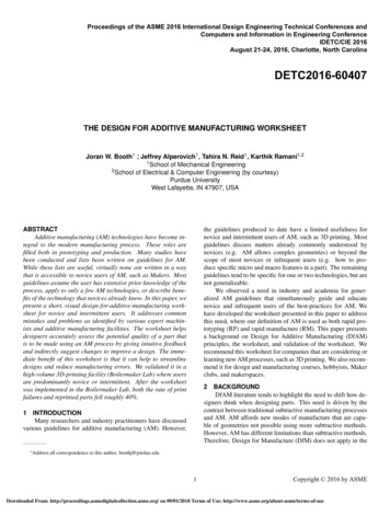
Infill Geometry Infill geometry can affect bothstrength and printing time Rectangular Strong in all directions and can be fastto printRectangularTriangular Triangular Strong in direction of walls but takeslonger to print Wiggle Allows part to be soft/twist/compress Hexagonal Strong in all directions and quick toprintWiggle/Zig-ZagHexagonal
Shell Shell is the outer “skin” of the part Increasing shell thickness canincrease overall strength of partwithout increasing material neededfor infill Increased shell thickness is alsobeneficial if part is to be sandedafter printing Increased shell thickness alsoprovides localized strengthening ofpart features
Part Orientation – Support Material To avoid needing supportmaterial, orient your prints in away that minimizes overhangs
Part Orientation – Surface Finish Optimize the orientation of the model to avoid the appearance ofstepping in the z-direction
Part Orientation – Load If the 3D printed part will bear a load, consider the application anddirection of the load when deciding how to orient the part
Part Orientation – Surface Area Design parts so that the amount of surface area in contact with theprint bed is maximized Ideally, this will be a large, flat face
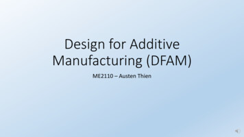
Part Orientation – Holes Cylindricity Vertical orientation is a stack ofconcentric circles Horizontal orientation is layeredrectangles of different width Cylindrical parts with verticalaxis generally have bettersurface finish and cylindricity
AM in Mechanism Design
Conveying Information If you want your part to conveyinformation to the user, considerconveying it with: ColorGeometryHapticsLightBraille MapLithophane
Consolidating Parts If you are considering 3Dprinting parts of an assembly, tryto consolidate the parts Using additive manufacturing toconsolidate parts can achieve: Better functional performanceReduced assembly timeIncrease robustnessAchieve multiple functions
Consolidating Parts Access to support material forremoval Difficult when consideringcomplex assemblies Soluble support is ideal for thisreason Access to critical componentswithin assembly Troubleshooting electronics Replacement of failed partsExampleSupportMaterialLocation
Bolted Connections Thread Wear Threaded Insert Captive Nuts Circle vs Square Bolt Hole CrossSection Competition Tip: Boltedconnections means more tools(ie screwdriver, hex key, socketwrench) and more time neededto disassemble joints
Snap-Fit Connections Cantilever Most commonly used Ball and cup Allows for motion Snap-Fit Pivot Allows for motion
Snap-Fit Connections Design Rules Tolerances vary from machine tomachine Fillets, not sharp corners Wide clips Retraction angle Build direction Final position Competition Tip: Less steps neededto disassemble joint so less timerequired for trouble shooting
Slot-Follower Connections Barrel Bolt Discrete positioning Dove-Tail Slot Stationary T-slot 8020 aluminum extrusioninterface Competition Tip: Lesssteps needed todisassemble joint so lesstime required for troubleshooting
Conclusion 3D printing is a great tool to rapidly make custom parts Some things for designers to remember: We can increase the likelihood of a successful print in the design phase aswell as in the manufacturing setup phase Consider how part orientation on the print bed will affect the finishedproduct Generally, we want to try to reduce the amount of time for a print, and avoidusing support material
“Additive manufacturing uses data computer-aided-design (CAD) software or 3D object scanners to direct hardware to deposit material, layer upon layer, in precise geometric shapes.” –GE Additive Additive manufacturing adds material to create an object Traditional manufacturing is s