Transcription
University of Arkansas, FayettevilleScholarWorks@UARKLandscape Architecture Undergraduate HonorsThesesLandscape Architecture12-2013Between the Posts: Research on the Cap and TopRail to Guardrail Post ConnectionBlake BucknerUniversity of Arkanasas, FayettevilleFollow this and additional works at: http://scholarworks.uark.edu/larcuhtRecommended CitationBuckner, Blake, "Between the Posts: Research on the Cap and Top Rail to Guardrail Post Connection" (2013). Landscape ArchitectureUndergraduate Honors Theses. 5.http://scholarworks.uark.edu/larcuht/5This Thesis is brought to you for free and open access by the Landscape Architecture at ScholarWorks@UARK. It has been accepted for inclusion inLandscape Architecture Undergraduate Honors Theses by an authorized administrator of ScholarWorks@UARK. For more information, please contactscholar@uark.edu.
Between the Posts: Research on the Cap and Top Rail to Guardrail PostConnectionA thesis submitted in partial fulfillment of the requirements of the Honors Program of theDepartment of Landscape Architecture in the Fay Jones School of Architecture,University of ArkansasBlake BucknerThesis Committee:Chair, Mark BoyerMember, Kimball ErdmanMember, Dr. Micah HaleFall 2013
Blake BucknerTable of ContentsIntroduction . . . . . . . . . . . . . . . . . . . . . . . . . . . . . . . . . . . . . . . . . . . . . . . . . . . . . . . . . .3-4Literature Review . . . . . . . . . . . . . . . . . . . . . . . . . . . . . . . . . . . . . . . . . . . . . . . . . . . . 4-19Methodology . . . . . . . . . . . . . . . . . . . . . . . . . . . . . . . . . . . . . . . . . . . . . . . . . . . . . . .19-31Results . . . . . . . . . . . . . . . . . . . . . . . . . . . . . . . . . . . . . . . . . . . . . . . . . . . . . . . . . . . 31-34Discussion . . . . . . . . . . . . . . . . . . . . . . . . . . . . . . . . . . . . . . . . . . . . . . . . . . . . . . . . 34-38Page 2
Blake BucknerIntroductionBetween 2003 and 2007, an estimated 11,120 Americans went to the emergencyroom as a direct result of a structural failure or collapse of wood deck railings. This is anaverage of 2,224 people each year. Furthermore, estimates show there are over 40million decks in the United States and about half of these are more than fifteen yearsold, which is past their expected lifespan (Legacy Services, 2012). Decks are exteriorstructures susceptible to the elements that degrade over time, making the need forproper, safe construction techniques even more important. The safety of unsuspectingpeople who use decks and rely on the deck’s safety components is at stake.The 2012 International Residential Code states that guardrails and handrailsmust withstand a 200-pound “single concentrated load applied in any direction at anypoint along the top.” (Table R301.5). A fair amount of research and testing has beendone to ensure that guardrail posts meet this requirement but not the rest of theguardrail system. Two studies, one at Virginia Tech (Loferski et al., 2005) and the otherat the University of Maryland (Morse, 2005), have been pretty widely disseminatedonline and through Professional Deck Builder Magazine, which has had follow-uparticles as well (“Question & Answers”, 2011). These studies found that all of thetraditional guardrail post to joist connections failed to meet the code requirement butthat the use of certain brackets, such as the Simpson StrongTieTM HD2A and theDeckLok bracket would make the posts code-compliant. These studies have certainlyhelped to make decks safer, but what about the space between the guardrail posts?There is typically at least six feet between posts, obviously comprising the vast majorityof the guardrail system of a deck. This space between the posts relies mainly on thePage 3
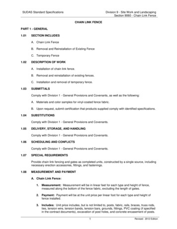
Blake Bucknercap rail and top rails to keep people from falling through and they also need to meet the200-pound concentrated load safety requirement, but do they? That is the mainquestion and area of research for this paper as there has been practically no testingdone on this subject.Literature ReviewWhen searching for common methods of cap and top rail attachment, two thingsbecame apparent: the sheer variety of possible connections but also the ambiguity as tohow they are actually achieved. With a focus solely on the most common guardrailsystem, wood, a search through professional reference books, Do-It-Yourself books,websites, on-line videos, and real world examples revealed many different connectionsand methods of construction. Research also focused on materials that would beavailable to the average contractor or “weekend warrior,” except for possibly theprofessional reference books.A look at professional reference books revealed little about the cap and top rail toguardrail post connection. The only one that showed details of this connection was theLandscape Architectural Graphic Standards (Hopper, 2007). It gives two details for anexclusively wood guardrail system (Fig. 1). Example A has a horizontal, continuous 2x6cap rail running centered over the tops of the guardrail posts with horizontal 2x4 toprails directly beneath, which can be assumed to only run between the posts. The bottomrail mimics the top rail and galvanized screws are shown going through the top andbottom rails into the ends of the 2x2 balusters held centered between them. Nothing ismentioned as to how the cap, top, and bottom rails are fastened to the guardrail postsPage 4
Blake Buckneror each other. The other detail, example B, shows an independent, continuous 2x6 caprail on edge, attached to the upper inside surface of the guardrail posts. The 5/4x4 topand bottom rails are attached to the posts in the same way with 2x2 balusters attachedto their outside surfaces. There is no mention offasteners.Figure 1. Landscape Architectural Graphic Standards, pg. 591Example A, on the left, shows a continuous cap rail runningover the posts with discontinuous top and bottom rails betweenthe posts. Example B, on the right, is quite unique with the cap,top, and bottom rails all attached flush to the inside surface ofthe posts. Another version of this example was not seen again.A search through Do-It-Yourself books was much more fruitful in terms of variety,but the ambiguity was still there. The local home improvement stores had only one DIYbook that went into detail on the cap/top rail to guardrail post connection. This was aBlack & Decker book: The Complete Guide to Decks, Updated 5th Edition (CreativePublishing international, 2012). It provides pretty good step-by-step instructions, and inessence it calls for a continuous, 2x4 top rail on edge that is attached flush to the insidesurface of the guardrail posts with two-and-a-half inch deck screws or 10d nails at scarfjoint splices. A continuous 2x6 cap rail is laid flat atop the top rail and the posts, alsoattached with two-and-a-half inch deck screws or 10d nails at scarf joints (Fig. 2). Thereis no bottom rail, as the balusters extend down to attach to the joists (the guardrail postsare not notched), with two two-and-a-half inch deck screws at the top and bottom.Page 5
Blake BucknerFigure 2. Black & Decker: The Complete Guide to Decks, pg.169. This image shows how all the rails are continuous,except where scarf joints are needed. The cap rails run overthe posts and the top and bottom rails attach flush to theinside surface of the posts.Various other Do-It-Yourself books were available at local bookstores. TheComplete Deck Book: Everything You Need to Plan, Build, or Buy the Perfect Deck forYour Home, a Sunset Book (Beneke, 2002), called for something very similar to whatBlack & Decker recommended except with a bottom rail for the balusters to end on witha sweep space below (Fig. 3).The fasteners were not specified.Figure 3. Complete Deck Book pg. 152This example is very similar to the Black& Decker guardrail example shownabove, except lacks detail on what fasteners to use. A maximum post spacing of six feet is also specified.Page 6
Blake BucknerA Reader’s Digest book, The Family Handyman: Decks, Patios, and Porchesdetailed quite an interesting connection (Reader’s Digest Association, 2002). Figure 4shows how the guardrail posts extend past the top of the cap rail so it calls for adiscontinuous, horizontal 2x4 cap rail that is toe-nailed on the short sides to the postswith a 10d galvanized casing nail and from underneath with two, two inch No. 10galvanized screws at an upward angle. Centered directly beneath the 2x4 is a horizontal1x3 which is somehow attached to the cap rail and/or posts but is not shown. What isshown are two nails going through either just thehorizontal top rail or both the cap and top rail to thetops of the balusters to hold them in place. The bottomrail is a horizontal 2x4, just like the cap rail.Figure 4. The Family Handyman: Decks, Patios, and Porches, pg.21. All of the rails are discontinuous between the posts and a curious system involving a laid flat 1x3 asthe top rail is shown. The common method of toe-nailing to attach the rails to the posts is also shown.The final Do-It-Yourself book is a bit older and depicts a guardrail system notseen much in more recent ones but is still not entirely uncommon (Beneke, 1998). It isan interesting detail because although the 2x6 cap rail is continuous and runs over thetops of the guardrail posts, it is entirely independent since the top rail sits an inch or twobelow (Fig. 5). This means the cap rail is only fastened at the posts and nowhere else.The top and bottom rails are 2x4s secured on edge, with 2x2 balusters running betweenthem. There is no indication of whether the top and bottom rail are continuous andPage 7
Blake Bucknermounted to the face of the posts or are discontinuous and mounted between the posts.Fasteners were not specified.Figure 5. Better Homes & Gardens: Deck Projects, pg. 54And independent cap rail runs over the posts but whetherthe top and bottom rails are continuous or not is not clear.The internet was slightly more rewarding than Do-It-Yourself books, offering asimilar amount of variety but a bit more detail on the actual connections. Decks.comrecommends a horizontal, continuous 2x6 cap rail, centered atop the guardrail postswith a vertical 2x4 top rail just beneath, flush with the inside surface of the posts (Fig. 6).The 2x4 bottom rail is installed the same as the top rail with 2x2 balusters attached totheir outer surface. There is nomention as to what type of fastener touse (Decks.com, 2012).Figure 6. http://www.decks.com/Deckbuilding/Wood Deck Rail PartsIt is clear that the top and bottomrails are discontinuous between the posts but there is still no mention of fasteners.Deckplans.com goes into more detail and switches up the dimensions of the capand top rail while also extending the guardrails up past the 36 inch height of the cap rail(DekBrands, 2012). This website says to first attach a 2x6 top rail on edge between theposts, flush to their inside face with four deck screws toe-nailed from the top and bottomPage 8
Blake Bucknerat each end to hold it in place (Fig. 7). Then a 2x4 cap rail goes on top, discontinuousbetween the posts and attached with deck screws to the top rail every 16-20 inches(Fig. 8). There is no bottom rail as the posts are notched at the bottom and the 2x2balusters go down to attach directly to the joists, fastened with one two-and-one-halfinch deck screw at both the top and bottom (Fig. 9).Figure drail-posts/step-3This figure shows how thedeck screws are toe-nailed from the top and bottom tohold the top rail in place.Figure drail-posts/step-4The cap rail is attached tothe top rail through deck screws every 16-20 inches,with screws close to posts as well.Figure drail-posts/step-7This figure shows how thebalusters are attached with one screw per end.Page 9
Blake BucknerThere are two articles from the website HammerZone.com and they went into themost detail of all the websites mentioned here. In the first article, 2x4s were used for thecap, top, and bottom rails (Maki, 2003). Where possible the cap rail went over theguardrail posts but at some locations had to stop at posts which supported an overheadstructure. The top rail was installed on edge, flush with the top of the posts, and nearlyflush with the inside surface of the posts so that it and the 2x2 balusters would becentered on the posts. The top rails were fastened with four, three inch deck screwsdriven in at an angle at the tops and bottoms of each end (Figs 10 & 11). The bottomrail was installed essentially the same way except with two screws driven in diagonallyat each end from the inner surface into the posts (Figs 10 & 11). The balusters wereattached to the top and bottom rails’ outer surface. Three-inch deck screws were alsoused to fasten the cap rail,about every twelve inches orso to the top rail and two perlocation at posts and splices(Fig. 12).Figure il/contemporary/basic1/painted 2x4.htm This figureshows how three-inch deck screws were toe-nailed to attach the top and bottom rails to the posts.Page 10
Blake BucknerFigure il/contemporary/basic1/painted 2x4.htm Toenailed attachments are shownagain with discontinuous top andbottom rails.Figure il/contemporary/basic1/painted 2x4.htm Thisfigure shows a continuous 2x4cap rail that utilizes scarf jointsplices when needed.The other article (Maki, 2005) didn’t have quite as much information (Fig. 13). A2x4 was used for the top rail, secured on edge and flush to the outside surface of theguardrail posts. The fastener was not specified. The 2x6 cap rail was then attached as acontinuous, horizontal member, centered over the posts and top rail and possiblyattached with three-inch deck screws. The balusters were 2x2s fastened with two, twoand-one-half inch deck screws at both ends, with the bottom ends attached to the joists.Page 11
Blake BucknerFigure 2/build6p2.html Top and bottom rails arecontinuous and attached to theoutside surface of the posts.Two-and-one-half, and threeinch deck screws arementioned as fasteners.Page 12
Blake BucknerAlso somewhat informative were online videos, provided by Lowe’s, HomeDepot, and Decks.com. In the Lowe’s video they notched the inside top of the guardrailposts for a 2x4 top rail to fit and fastened it with screws (Lowe’s, 2009). The cap rail wascontinuous 5/4x6 decking material, laid flat, and centered over the posts. 2x2 balusterswere attached to the top rail and joists at the bottom (the bottom of the guardrail postswere notched), with just one screw per location, two screws seemed to be used at everyotherattachmentlocation (Fig 14).Figure 14.http://www.youtube.com/watch?v RwNsJ5sFjHcCompleted deck withcontinuous cap rail anddiscontinuous top and bottomrails. Screws seemed to be used exclusively as fasteners. There was no mention of post spacing.Whereas the Lowe’s video used all screws, the Home Depot video used almostall nails (even to attach the guardrail posts to the joists!). The top rails were 2x4s butsimply installed on edge, with nails, to the inside surface of the guardrail posts, withoutnotching. There was a bottom rail that mimicked the top rail with 2x2 balusters nailed toit and the top rail (Fig. 15), with 5/4x6 continuous decking running atop the top rail andposts, this time fastened with decking screws (The Home Depot, 2008).Page 13
Blake BucknerFigure 15.http://www.youtube.com/watch?v 9y9560S5a0Q A nailgun was used liberally duringthis video. Balusters arebeing attached with nails inthis figure.The Decks.com video used 2x4 top and bottom rails installed between guardrailposts attached with four, three-and-one-half inch trim screws driven in diagonally, twoper end (“How to Build Deck Railings”, 2012). 2x2 balusters run between, fastened withtwo-and-one-half inch trim screws, one at each top and bottom. A 2x6 or 5/4x6 (theyused 2x6) horizontal cap rail is suggested, screwed in place and discontinuous sincethe posts extend up pastit (Fig. 16).Figure 16.http://www.youtube.com/watch?v c84wb8Z660c All of therails were discontinuous inthis video as the posts extendpast the cap rail. Screwsseemed to be used exclusively as fasteners and there was no mention of post spacing.Page 14
Blake BucknerThe final area of research was real world examples in Fayetteville, Arkansas.About ten locations were visited, most of them being wood walkways for lowerincome/student apartment buildings near Leverett and Deane Streets because theywere semi-public and access was possible. Again, there was a surprising amount ofvariety, but one thing that was noticeable was that nails were used more often thanscrews. However, this could be attributable to the generally older construction of thesedecks. The first example (Fig. 17) is actually a bit different than the others since it is aprivate deck located just outside of city limits, almost fifteen years old. Galvanized nailsare the only fasteners and the guardrail posts are curiously notched on the outside forthe 2x4 top rail. A 2x6 continuouscap rail is centered above the postsand the balusters attach to theoutside surface of the top rail andthe joists below.Figure 17. Residential deck with the tops ofthe posts notched to receive the top rails.The next example is from apartments across from the Lewis Soccer Fields (Fig.18). This example also used all nails with a continuous 2x6 cap rail centered above theguardrail posts with 2x4 top rails running directly beneath, discontinuous between, andflush with the inside of the posts. 2x2 balusters extend down to attach to the joists.Page 15
Blake BucknerFigure 18.Apartments on Lewis Avenue with acontinuous cap rail and discontinuous top rails. Nailswere the only fasteners used.The final example, or at least some variation on it, was fairly common becausethe guardrail posts often extended up to support an overhanging roof or more walkways(Fig. 19). This makes the cap, top, and bottom rails discontinuous. Here a 2x6 is usedfor the cap rail, 2x4s for the top and bottom rails, and 2x2s for the balusters. The topand bottom rails are flush with the inside surface of the posts and the balusters areattached to their outside surface. Nails were mostly used at this location but somescrews were used to attach the cap rail to the top rail and posts.Page 16
Blake BucknerFigure 19. Apartments near Cleveland and Storer withall rails discontinuous. Nails were used to attach thebottom rails to the posts and some separation can beseen in this figure where the nails have completelypulled out or sheared off.The literature search also focused on guardrail post spacings since a maximumis not stated by code. A six foot spacing was the most-recommended in the literature.Although only one real world example had the posts six feet on center and the averagespacing from a sample of eight different locations was just under nine feet, the literatureis pretty clear about calling for a six foot maximum spacing. In fact, the only specifiedspacing length for wood deck guardrail posts besides six feet was one for five feet andanother for four feet. The previously mentioned Complete Deck Book (Beneke, 2002),the Deckplans.com website (DekBrands, 2012), and the Decks.com video (“How toBuild Deck Railings” 2010) specify a six foot maximum spacing while the Better Homesand Gardens book specified five feet (Beneke, 1998). Other resources, such as theAmerican Wood Council’s “Prescriptive Residential Wood Deck Construction Guide”,recommends a six foot maximum spacing, while Portland, Oregon’s “Deck DesignGuide” specifies a four feet maximum spacing. There appears to be nothing in the localPage 17
Blake Buckner(Fayetteville’s), national, or international building codes which specifies wood deckguardrail post spacing maximums. A six foot spacing was therefore chosen to representthe most common, but also largest, spacing specified by the literature.Fastener use was the last final area researched. In the real world examples, nailsappeared more frequently than screws. However, all of the real world examples visitedlooked to be at least a decade old and did not reflect what was found in the literature,especially the newer literature. With the exception of the Home Depot video, the oldestDo-It-Yourself book (Beneke, 1998), and the Black & Decker book (Creative Publishinginternational, 2012), nails were not used. It should also be noted that nails were onlyspecified for use at splices or scarf joints in the Black & Decker book. Therefore, a largemajority of the literature specifies screws rather than nails. Even though they take moretime and labor, a good contractor should use screws rather than nails to construct decksbecause of nails’ tendency to pull out and weaken connections over time. For thesereasons, it seems that screws rather than nails should be used to construct wood deckguardrails.All in all, the strongest of the examples found in the literature review generallyrely on eight (two per cap and top rail per end) toe-nailed screws to hold everythingbetween the posts in place and resist 200 pounds of force. In a laboratory setting, the200 pounds is magnified by 2.5 as a safety factor for a 500 pound total load as per the2012 International Building Code instructions: “the test specimen shall be subjected toan increasing superimposed load until structural failure occurs or the load is equal totwo and one-half times the desired superimposed design load” (1710.3.1). Furthermore,apply this 500-pound force three or more feet from where the cap and top rails connectPage 18
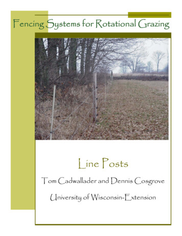
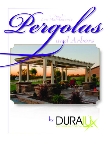
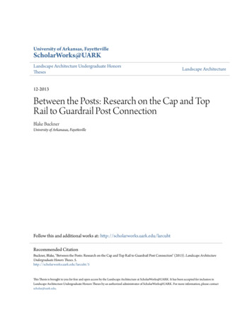
Blake Bucknerto the guardrail post and this becomes a minimum of a 1,500 pound moment force,certainly a lot to overcome. Especially after seeing the real world examples, it wasdoubtful that any of the above-mentioned examples would pass this test, which wouldrender almost all deck guardrails not code-compliant and likely dangerous. Testing andresearch needed to be done to make the space between the posts safe as well.MethodologyWhen looking at all of the sources in the literature review and takingcommonalities from them all, three main types, or simply “Guardrails,” emerged thatseemed to encompass nearly all of the most common modes of construction. Guardrail1 is where the cap, top, and bottom rails are discontinuous because the guardrail postsextend up past them (Fig. 4, 7-9, 16, and 19). This is somewhat common for eitheraesthetic or functional purposes such as supporting an overhead structure or even otherwooden walkways or balconies above, as witnessed at several of the apartmentbuildings. This Guardrail relies solely on toe-nailed fasteners to hold the guardrailsystem in place between the posts (page 20).The next system, Guardrail 2, is where the top and bottom rails are discontinuousbut the cap rail runs continuously over the tops of the guardrail posts (Fig. 5, 6, 1012,18, and example A in Fig. 1). This is quite common but the top and bottom rails stillrely on toe-nailed fasteners and although the cap rail is no longer toe-nailed, it isfastened into the end-grain of the guardrail posts which is about half as strong asfastening to the edges of the posts (page 21).Page 19
Blake Buckner6' O.C.5' - 8 1/2 "4x4 Guardrail Post2x6 Cap Rail2x4 Top Rail2x2 Baluster3" Coated Deck Screw2 1/2" GalvanizedDeck Screw2'3'3 1/2"2"Top of Decking (not constructed)2x4 Bottom RailGUARDRAIL 1 - ELEVATION7 1/4"SCALE: 1" 1'-0"2"Steel Channel1/2" dia. Bolt4x4 Guardrail Post3" Coated Deck Screw4x4 Guardrail Post3" Coated Deck Screw2x4 Top Rail2x6 Cap Rail2 1/2" GalvanizedDeck Screw2x6 Cap Rail2x4 Top Rail2x2 Baluster2'-7"3'-1 1/2"2 1/2" GalvanizedDeck Screw2x4 Bottom Rail2x2 BalusterSteel Channel2"1/2" dia. Bolt2"CROSS SECTIONSCALE: 1" 1'-0"CAP/TOP RAIL DETAILSCALE: 1/2" 1'-0"Page 20
Blake Buckner6' O.C.5' - 8 1/2 "3" Coated Deck Screw2x6 Cap Rail2x4 Top Rail2x2 Baluster4x4 Guardrail Post2 1/2" GalvanizedDeck Screw2'3'3 1/2"2"Top of Decking (not constructed)2x4 Bottom RailGUARDRAIL 2 - ELEVATION7 1/4"SCALE: 1" 1'-0"2"Steel Channel1/2" dia. Bolt3" Coated Deck Screw3" Coated Deck Screw4x4 Guardrail Post2x4 Top Rail2x6 Cap Rail2x6 Cap Rail2x4 Top Rail2 1/2" GalvanizedDeck Screw2x2 Baluster4x4 Guardrail Post2'-7"3'-1 1/2"2 1/2" GalvanizedDeck Screw2x2Baluster2x4 Bottom RailSteel Channel2"1/2" dia. Bolt2"CROSS SECTIONSCALE: 1" 1'-0"CAP/TOP RAIL DETAILSCALE: 1/2" 1'-0"Page 21
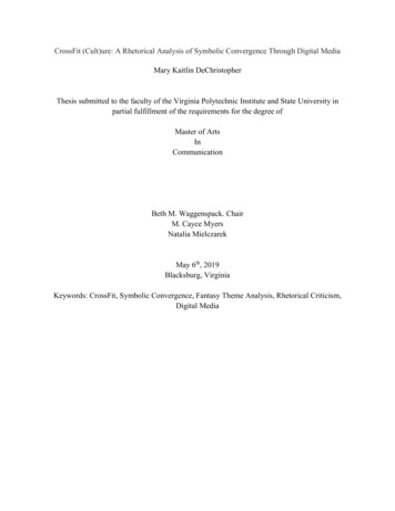
Blake BucknerThe last common mode of construction, Guardrail 3 uses continuous cap, top,and bottom rails by having the cap rail run over the tops of the guardrail posts and thetop and bottom rails fastened flush to their inside surface (Fig. 2, 3, 13-15, and 17). Thetop and bottom rails could be fastened to the outside surface of the posts instead, butthis configuration was not tested since it was not seen as often and its opposite, whichshould theoretically better resist forces from the usable side of the deck, could bespecified just as easily. Here the top and bottom rails are attached straight to theguardrail posts and not into the end-grain (page 23). Also, if the force is directed awayfrom the deck, the top and bottom rails would probably have to snap in order for thissystem to completely fail. This is unlikely to occur but is still a possibility.One more system, Guardrail 4, seemed like it should also be tested (Fig. 20-21).This system is very similar to Guardrail 1 or 2 except that it uses “rail-set brackets” bythe manufacturer Tehk (DecksDirect.com, 2012). The top and bottom rails are attachedusing powder-coated steel brackets on each end that are fastened to the guardrailsposts with four, one-and-one-half inch square drive stainless steel screws. One morescrew going up from the bottom attaches the bracket to the top or bottom rail. Thissystem should be quite strong since the steel brackets cover a decent amount of the topor bottom rail on both sides of their ends. Again they are also attached with four screwsdriven straight into the guardrail post which doesn’t seem likely to pull out. Testing thissystem should mimic Guardrail 1 so as to determine if the brackets will hold up with thesupposedly weakest system (page 24). It still remains to be seen if it will be strongerthan Guardrail 3 with its lack of brackets, however.Page 22
Blake Buckner4x4 Guardrail Post6' O.C.5' - 8 1/2 "3" Coated Deck Screw2x6 Cap Rail2x4 Top Rail2x2 Baluster2 1/2" GalvanizedDeck Screw2'3'3 1/2"2"Top of Decking (not constructed)2x4 Bottom RailGUARDRAIL 3 - ELEVATION7 1/4"SCALE: 1" 1'-0"2"Steel Channel1/2" dia. Bolt3" Coated Deck Screw3" CoatedDeck Screw2x4 Top Rail4x4 Guardrail Post2x6 Cap Rail2x6 Cap Rail2x4 Top Rail2 1/2" GalvanizedDeck Screw2x2 Baluster2'-7"3'-1 1/2"2 1/2" GalvanizedDeck Screw2x4 Bottom Rail2x2Baluster4x4 Guardrail PostSteel Channel2"1/2" dia. Bolt2"CROSS SECTIONCAP/TOP RAIL DETAILSCALE: 1" 1'-0"SCALE: 1/2" 1'-0"Page 23
Blake Buckner6' O.C.5' - 8 1/2 "3" Coated Deck Screw2x6 Cap Rail2x4 Top Rail2x2 Baluster4x4 Guardrail Post1 1/2" Stainless Steel Screw2 1/2" GalvanizedDeck Screw2'3'Rail-set Bracket by Tehk2"Top of Decking (not constructed)2x4 Bottom Rail3 1/2"GUARDRAIL 4 - ELEVATION7 1/4"SCALE: 1" 1'-0"2"1/2" dia. Bolt4x4 Guardrail Post3" Coated Deck ScrewSteel Channel4x4 Guardrail Post3" Coated Deck Screw1 1/2" Stainless Steel ScrewRail-set Bracket by Tehk2x6 Cap Rail2 1/2" GalvanizedDeck Screw2x6 Cap Rail2x4 Top Rail2x2 Baluster2x4 Top Rail2'-7"3'-1 1/2"2 1/2" GalvanizedDeck Screw2x4 Bottom Rail2x2 BalusterSteel Channel2"1/2" dia. Bolt2"CROSS SECTIONSCALE: 1" 1'-0"CAP/TOP RAIL DETAILSCALE: 1/2" 1'-0"Page 24
Blake BucknerFigure ery/id/7244/image/3729/ Tehk Rail-SetBracket and the screws used to fasten it to thepost and rail.Figure ery/id/7244/image/3730/ Tehk Rail-SetBracket as it is installed.As mentioned in the literature review, all Guardrails were constructed with theposts six feet on center and screws rather than nails were used as the fasteners.Page 25
Blake BucknerMaterials:All of the lumber used to construct the Guardrails was purchased from CityLumber, a local business in Fayetteville, Arkansas. The grade of the lumber variedsome but all was Yellow Pine and MCA pressure-treated. All the 2x2s, 2x4s, and 2x6swere of the higher, #1 grade while the 4x4s were #2 grade. At every connection besidesthose involving the Tehk brackets and balusters, three inch long, #9, Phillips drive,coated deck screws were used. Where the balusters connected to the top and bottomrails, two-and-a-half inch long, #8, square drive, galvanized deck screws were used. Toattach the Guardrails to the testing apparatus, five inch long, one-half inch diameterbolts and their corresponding nuts and washers were used. Two bolts per post wereused and the attachment pattern mimicked actual connections to joists or band joists.The lumber was delivered all at once and left outside until what was needed wasbrought inside to construct the Guardrails, which were left inside until they were tested.The amount of time each piece of lumber spent outside or inside varied, one could evensay significantly, but moisture content readings on the lumber were taken right beforeeach test (Table 2) and prove that the moisture content, and therefore strength, did notactually differ greatly. Three samples of each Guardrail were constructed and all thesamples of one Guardrail were tested during the same testing period.Testing Set-Up and Protocol:Testing took place at the University of Arkansas’ Engineering Research Center.The testing location had a long,
Landscape Architectural Graphic Standards (Hopper, 2007. It ) gives two details for an exclusively wood guardrail system (Fig. 1). Example A has a horizontal, continuous 2x6 cap rail running centered over the tops of the guardrail posts horizontal with2x4 top rails directly beneath, which can be assumed to only run between the posts. The bottom