Transcription
Lassen iQ GPS ReceiverSystem Designer Reference ManualPart Number 54854-00Revision AFebruary 2005
Corporate OfficeRelease NoticeTrimble Navigation LimitedComponents Technologies Division749 North Mary AvenuePost Office Box 3642Sunnyvale, CA 94088-3642U.S.A.Phone: 1-408-481-8940, 1-800-545-7762Fax: 1-408-481-7744www.trimble.comThis is the February 2005 release (Revision A) ofthe Lassen iQ GPS Receiver System DesignerReference Manual, part number 54854-00.The following limited warranties give you specificlegal rights. You may have others, which varyfrom state/jurisdiction to state/jurisdiction.Waste Electrical and Electronic Equipment(WEEE) NoticeSupport OfficesTrimble Navigation LimitedComponents Technologies Division749 North Mary AvenuePost Office Box 3642Sunnyvale, CA 94088-3642U.S.A.Phone: 1-408-481-8940, 1-800-545-7762Fax: 1-408-481-7744Trimble Navigation Europe LimitedTrimble HouseMeridian Office ParkOsborn Way, HookHampshire RG27 9HXEnglandPhone: 44-1256-760-150Fax: 44-1-256-760-148Copyright and Trademarks 2005 Trimble Navigation Limited. All rightsreserved. No part of this manual may be copied,reproduced, translated, or reduced to anyelectronic medium or machine-readable form forany use other than with the Lassen iQ GPSReceiver.The Globe & Triangle logo, Trimble, Colossus,FirstGPS, and Lassen, are trademarks of TrimbleNavigation Limited.The Sextant logo with Trimble is a trademark ofTrimble Navigation Limited, registered in theUnited States Patent and Trademark Office.All other trademarks are the property of theirrespective owners.This Trimble product is furnished on an OEMbasis. By incorporating this Trimble product withyour finished goods product(s) you shall bedeemed the “producer” of all such products underany laws, regulations or other statutory schemeproviding for the marking, collection, recyclingand/or disposal of electrical and electronicequipment (collectively, “WEEE Regulations”) inany jurisdiction whatsoever, (such as for examplenational laws implementing EC Directive 2002/96on waste electrical and electronic equipment, asamended), and shall be solely responsible forcomplying with all such applicable WEEERegulations.Hardware Limited WarrantyTrimble warrants that this Trimble hardwareproduct (the “Product”) shall be free from defectsin materials and workmanship and willsubstantially conform to Trimble’s applicablepublished specifications for the Product for aperiod of one (1) year, starting from the date ofdelivery. The warranty set forth in this paragraphshall not apply to software/firmware products.
Software and Firmware License, LimitedWarrantyThis Trimble software and/or firmware product(the “Software”) is licensed and not sold. Its use isgoverned by the provisions of the applicable EndUser License Agreement (“EULA”), if any,included with the Software. In the absence of aseparate EULA included with the Softwareproviding different limited warranty terms,exclusions, and limitations, the following termsand conditions shall apply. Trimble warrants thatthis Trimble Software product will substantiallyconform to Trimble’s applicable publishedspecifications for the Software for a period ofninety (90) days, starting from the date ofdelivery.Warranty RemediesTrimble's sole liability and your exclusive remedyunder the warranties set forth above shall be, atTrimble’s option, to repair or replace any Productor Software that fails to conform to such warranty(“Nonconforming Product”), or refund thepurchase price paid by you for any suchNonconforming Product, upon your return of anyNonconforming Product to Trimble in accordancewith Trimble’s standard return materialauthorization procedures.Warranty Exclusions and DisclaimerThese warranties shall be applied only in the eventand to the extent that: (i) the Products andSoftware are properly and correctly installed,configured, interfaced, maintained, stored, andoperated in accordance with Trimble’s relevantoperator's manual and specifications, and; (ii) theProducts and Software are not modified ormisused.The preceding warranties shall not apply to, andTrimble shall not be responsible for defects orperformance problems resulting from (i) thecombination or utilization of the Product orSoftware with products, information, data,systems or devices not made, supplied or specifiedby Trimble; (ii) the operation of the Product orSoftware under any specification other than, or inaddition to, Trimble's standard specifications forits products; (iii) the unauthorized modification oruse of the Product or Software; (iv) damagecaused by accident, lightning or other electricaldischarge, fresh or salt water immersion or spray;or (v) normal wear and tear on consumable parts(e.g., batteries).THE WARRANTIES ABOVE STATE TRIMBLE'SENTIRE LIABILITY, AND YOUR EXCLUSIVEREMEDIES, RELATING TO PERFORMANCE OFTHE PRODUCTS AND SOFTWARE. EXCEPT ASOTHERWISE EXPRESSLY PROVIDED HEREIN,THE PRODUCTS, SOFTWARE, ANDACCOMPANYING DOCUMENTATION ANDMATERIALS ARE PROVIDED “AS-IS” ANDWITHOUT EXPRESS OR IMPLIED WARRANTYOF ANY KIND BY EITHER TRIMBLENAVIGATION LIMITED OR ANYONE WHO HASBEEN INVOLVED IN ITS CREATION,PRODUCTION, INSTALLATION, ORDISTRIBUTION, INCLUDING, BUT NOT LIMITEDTO, THE IMPLIED WARRANTIES OFMERCHANTABILITY AND FITNESS FOR APARTICULAR PURPOSE, TITLE, ANDNONINFRINGEMENT. THE STATED EXPRESSWARRANTIES ARE IN LIEU OF ALLOBLIGATIONS OR LIABILITIES ON THE PARTOF TRIMBLE ARISING OUT OF, OR INCONNECTION WITH, ANY PRODUCTS ORSOFTWARE. SOME STATES ANDJURISDICTIONS DO NOT ALLOW LIMITATIONSON DURATION OR THE EXCLUSION OF ANIMPLIED WARRANTY, SO THE ABOVELIMITATION MAY NOT APPLY TO YOU.TRIMBLE NAVIGATION LIMITED IS NOTRESPONSIBLE FOR THE OPERATION ORFAILURE OF OPERATION OF GPS SATELLITESOR THE AVAILABILITY OF GPS SATELLITESIGNALS.
Limitation of LiabilityTRIMBLE’S ENTIRE LIABILITY UNDER ANYPROVISION HEREIN SHALL BE LIMITED TOTHE GREATER OF THE AMOUNT PAID BY YOUFOR THE PRODUCT OR SOFTWARE LICENSE ORU.S. 25.00. TO THE MAXIMUM EXTENTPERMITTED BY APPLICABLE LAW, IN NOEVENT SHALL TRIMBLE OR ITS SUPPLIERS BELIABLE FOR ANY INDIRECT, SPECIAL,INCIDENTAL, OR CONSEQUENTIAL DAMAGESWHATSOEVER UNDER ANY CIRCUMSTANCEOR LEGAL THEORY RELATING IN ANY WAY TOTHE PRODUCTS, SOFTWARE, ANDACCOMPANYING DOCUMENTATION ANDMATERIALS, (INCLUDING, WITHOUTLIMITATION, DAMAGES FOR LOSS OFBUSINESS PROFITS, BUSINESS INTERRUPTION,LOSS OF BUSINESS INFORMATION, OR ANYOTHER PECUNIARY LOSS), REGARDLESS OFWHETHER TRIMBLE HAS BEEN ADVISED OFTHE POSSIBILITY OF ANY SUCH LOSS ANDREGARDLESS OF THE COURSE OF DEALINGWHICH DEVELOPS OR HAS DEVELOPEDBETWEEN YOU AND TRIMBLE. BECAUSE SOMESTATES AND JURISDICTIONS DO NOT ALLOWTHE EXCLUSION OR LIMITATION OF LIABILITYFOR CONSEQUENTIAL OR INCIDENTALDAMAGES, THE ABOVE LIMITATION MAY NOTAPPLY TO YOU.
Table of ContentsTable of Contents1234Starter KitProduct Overview . . . . . . . .Starter Kit . . . . . . . . . . . .Receiver Performance . . . . . .Interface Protocols. . . . . . . .Ordering Starter Kit ComponentsStarter Kit Interface Unit . . . . .Power . . . . . . . . . . . . . .Hardware Setup . . . . . . . . .Software Toolkit . . . . . . . . . .2. .3. .5. .6. .7. .8. 13. 15. 17Hardware IntegrationGeneral Description . . .Connectors . . . . . . .Power Requirements . .Serial Interface. . . . . .Serial Port Connections .Pulse-Per-Second (PPS)Mounting . . . . . . . . .GPS Antennas . . . . . . 20. 21. 25. 27. 28. 31. 32. 33Software InterfaceStart-up . . . . . . . . . . . . . . . . . . . . . .Communicating with the Lassen iQ GPS ReceiverPort Protocol and Data Output Options . . . . . .Custom Port Configuration . . . . . . . . . . . .Timing Applications . . . . . . . . . . . . . . . .Known Anomalies in Firmware Release 1.10 . . . 38. 39. 42. 47. 51. 52Operation and PerformanceIntroduction . . . . . . . . . . . . . . .GPS Satellite Message . . . . . . . . .Satellite Acquisition and Time to First FixSatellite Mask Settings . . . . . . . . .Standard Operating Modes . . . . . . . 54. 55. 56. 60. 63.Lassen iQ GPS Receiver
Table of ContentsDifferential GPS Operating Modes . . . . . .Position Accuracy . . . . . . . . . . . . . . .Coordinate Systems . . . . . . . . . . . . . .Performance Characteristics . . . . . . . . .Lassen iQ GPS Receiver Sensitivity Modes. .Lassen iQ GPS Receiver Aided GPS Feature.GPS Timing . . . . . . . . . . . . . . . . . .Pulse-Per-Second (PPS) . . . . . . . . . . .System Architecture . . . . . . . . . . . . . .AB. 64. 65. 66. 68. 70. 75. 78. 80. 82Trimble Standard Interface Protocol (TSIP)Interface Scope . . . . . . . . . . . . . . . . . .Packet Structure . . . . . . . . . . . . . . . . . .Automatic Output Packets . . . . . . . . . . . . .Customizing Receiver Operations . . . . . . . . .Automatic Position and Velocity Reports . . . . .Initialization Packets to Speed Start-up . . . . . .Packets Output at Power-Up . . . . . . . . . . .Timing Packets . . . . . . . . . . . . . . . . . .Satellite Data Packets . . . . . . . . . . . . . . .Backwards Compatibility. . . . . . . . . . . . . .Recommended TSIP Packets . . . . . . . . . . .Command Packets Sent to the Receiver . . . . .Report Packets Sent by the Receiver to the User .Key Setup Parameters or Packet BB . . . . . . .Packet Descriptions . . . . . . . . . . . . . . . .TAIP Message Output (Packet 0x7E) . . . . . . .TSIP Superpackets . . . . . . . . . . . . . . . . 86. 87. 88. 89. 89. 90. 91. 91. 92. 92. 93. 94. 96. 97102145156TSIP Tool kit User’s GuideiQ Monitor . . . . . . . . . . . . . . . . . . . . . . . . . . . . . . . 165Lassen iQ GPS Receiver
Table of ContentsCTrimble ASCII Interface Protocol (TAIP)Message Format. . . . . . . . . . . . . .Sample PV Message . . . . . . . . . . .Time and Distance Reporting . . . . . . .Latitude and Longitude Conversion . . . .Message Data Strings . . . . . . . . . . .Communication Scheme for TAIP . . . . ns and Mechanical DrawingsLassen iQ GPS Receiver Specifications. . .Ultra Compact Embedded Antenna . . . . .Compact Magnetic Mount Antenna . . . . .Compact Unpackaged Antenna . . . . . . .226232235240DGPSSK User’s Guide (TAIP)ENMEA 0183The NMEA 0183 Communication InterfaceNMEA 0183 Message Format . . . . . . .Field Definitions . . . . . . . . . . . . . .NMEA 0183 Message Options . . . . . .NMEA 0183 Message Formats . . . . . .Exception Behavior . . . . . . . . . . . .FGGlossaryLassen iQ GPS Receiver
Table of ContentsLassen iQ GPS Receiver
About this ManualWelcome to System Designer Reference Manual for the Lassen iQGPS receiver. This manual describes how to integrate and operate theLassen iQ GPS receiver.If you are not familiar with GPS, visit Trimble’s website,www.trimble.com, for an interactive look at Trimble and GPS.Trimble assumes that you are familiar with Microsoft Windows andknow how to use a mouse, select options from menus and dialogs,make selections from lists, and refer to online help.Technical AssistanceIf you have a problem and cannot find the information you need in theproduct documentation, contact the Trimble Technical AssistanceCenter at 800-767-4822.Your CommentsYour feedback about the supporting documentation helps us toimprove it with each revision. To forward your comments, send ane-mail to ReaderFeedback@trimble.com.Lassen iQ GPS Receiver
About this Manual6Lassen iQ GPS Receiver
CHAPTER1Starter Kit Product Overview Starter Kit Receiver Performance Interface Protocols Ordering Starter Kit Components Starter Kit Interface Unit Power Hardware Setup Software Toolkit1
11.1Starter KitProduct OverviewThe Lassen iQ GPS receiver is a full featured, ultra low power receiveron a miniature form factor, suitable for a variety of mobile, embeddedapplications. The Lassen iQ GPS receiver incorporates Trimble’sFirstGPSTM architecture in the form of two ASICS: Colossus RF downconverter and IO-C33 baseband chip.The IO-C33 integrates Trimble’s IO digital signal processor with theEpson C33 RISC processor, real-time clock, UART, and 1Mbitmemory. Together with the colossus RF, this implementation ofFirstGPS technology makes possible one of the smallest(26 mm x 26 mm x 6mm) and lowest power (less than 89 mW) GPSmodules available.The Lassen iQ GPS receiver outputs a complete position, velocity, andtime (PVT) solution in the NMEA Version 3.0 ASCII protocol, theTrimble ASCII Interface Protocol (TAIP), and the Trimble TSIPbinary protocol. A Pulse-Per-Second signal is available for veryaccurate timing applications.2Lassen iQ GPS Receiver
Starter Kit1.21Starter KitThe Starter Kit makes it simple to evaluate the Lassen iQ GPSreceiver’s exceptional performance. The Starter Kit can be used as aplatform for configuring the receiver module and as a platform fortroubleshooting your design. The Starter Kit includes: Shielded Lassen iQ GPS module mounted on an interfacemotherboard in a durable metal enclosure. The motherboardaccepts 9 - 32 VDC power and provides regulated 3.3V power tothe Lassen iQ GPS receiver. The motherboard also contains:–3.6V lithium battery that provides back-up power to thereceiver.–Circuitry to convert the TTL output to RS-232, enablingthe user to connect the RS-232 ports in the Starter Kit tothe PC COM port via an RS-232 cable connection. Compact Magnetic-Mount GPS Antenna with a 5 meter cable. Ultra-Compact Embedded Antenna with an 8 cm cable. 9-pin RS-232 interface cable. AC/DC power supply adapter (input: 100-240VAC,output: 12 VDC). DC power cable. Cigarette lighter adapter power cable. CD containing software tools used to communicate with thereceiver, the System Designer Reference Manual, and “C”programming source routines to be used as software templates forcommunicating directly with the receiver.Lassen iQ GPS Receiver3
11.2.1Starter KitRemoving the Lassen iQ GPS ModuleThe Lassen iQ GPS module is secured to the motherboard withdouble-sided adhesive tape allowing for easy removal and integrationwith the user’s application. (The adhesive tape used by Trimble is 3MScotch, part number 4945).Follow these steps to remove the module from the motherboard: Unplug the I/O cable and the RF cable from the module. Use a small flat-head screw driver to pry the Lassen iQ GPSreceiver module off the motherboard.Warning – When the Lassen iQ GPS receiver module is removed fromthe motherboard, the double-sided tape looses some of it’s adhesivequality. This adhesive tape may only be re-used for laboratory testing. Theoriginal adhesive tape should not be re-used for drive testing the StarterKit interface unit because the module could loosen and cause short circuitwhen contacting other motherboard components. If drive testing isrequired, use a new piece of double-sided adhesive tape to re-attach theLassen iQ GPS receiver module to the motherboard.4Lassen iQ GPS Receiver
Starter Kit1.31Receiver PerformanceThe Lassen iQ GPS receiver is a complete 12-channel parallel trackingGPS receiver designed to operate with the L1 frequency, StandardPosition Service, Coarse Acquisition code. Using two highlyintegrated Trimble custom integrated circuits, the receiver is designedin a modular format especially suited for embedded applicationswhere small size and extremely low power consumption are required.The receiver features Trimble's latest signal processing code, a highgain RF section for compatibility with standard 27 dB active gain GPSantennas, and a CMOS TTL level pulse-per-second (PPS) output fortiming applications or for use as a general purpose synchronizationsignal.The Lassen iQ GPS receiver acquires a position fix with minimaldelay after power cycling. The battery back-up RAM is used to keepthe Real Time clock (RTC) alive, and to store the following: Almanac Ephemeris Last positionUser settings such as port parameters, NMEA, and TAIPconfigurations can be stored in the receiver’s non-volatile (Flash)memory. These settings are retained without application of mainpower or battery back-up power.The Lassen iQ GPS receiver has two configurable serial I/Ocommunication ports.Warning – When customizing port assignments or characteristics,confirm that your changes do not affect your ability to communicate withthe receiver (see Chapter 3, Software Interface).Lassen iQ GPS Receiver5
Starter Kit11.4Interface ProtocolsThe Lassen iQ GPS receiver operates using one of three protocols —Trimble Standard Interface Protocol (TSIP), Trimble ASCII InterfaceProtocol (TAIP), or NMEA 0183. Protocol selection and portcharacteristics are user configurables. The factory default settings are:1.4.1 Port 1, TSIP bi-directional Port 2, NMEA 0183 OUT/RTCM SC-104 V2.1 INTSIPTSIP is a powerful binary packet protocol that allows the systemdesigner maximum configuration control over the GPS receiver foroptimum performance in any number of applications. TSIP supportsover 20 commands and their associated response packets for use inconfiguring the Lassen iQ GPS receiver to meet user requirements.1.4.2TAIPTAIP is the Trimble ASCII interface protocol designed specifically forvehicle tracking applications. It is a bi-directional protocol usingsimple ASCII commands with the associated ASCII responses.1.4.3NMEANMEA 0183 is an industry standard protocol common to marineapplications. NMEA provides direct compatibility with other NMEAcapable devices such as chart plotters, radars, etc. The Lassen iQ GPSreceiver supports most NMEA messages for GPS navigation. NMEAmessages and output rates can be user selected as required.1.4.4DGPSThe Lassen iQ GPS receiver can be configured for RTCM SC-104input which is the GPS industry standard for differential correctiondata. The receive side of Port 2 is factory configured to accept RTCMdata.6Lassen iQ GPS Receiver
Starter Kit1.51Ordering Starter Kit ComponentsThe Lassen iQ GPS receiver is available in a Starter Kit or as anindividual module and associated antenna. The Starter Kit(PN 51099-00) includes all the components necessary to quickly testand integrate the module: Compact Magnetic-Mount Antenna with 5m cable Ultra-Compact Embedded Antenna with 8cm cable AC/DC power supply adapter DC Power cable (3-wire) RS-232 interface cable DB9M/DB9F (pin to pin) Cigarette lighter adapter power cable CD-ROM containing software tools and the System DesignerReference ManualTable 1.1 provides ordering information for the Lassen iQ GPSmodule and the associated antennas and cables.Table 1.1Lassen iQ GPS Receiver Ordering InformationProductsPart NumberLassen iQ GPS receiver Module46240-10/46240-20Lassen iQ GPS receiver Starter Kit51099-00Antenna transition cable, MCX-HFL connector47274Antenna transition cable, SMA-HFL connector49894-05Ultra-Compact Embedded Antenna, 3.3V, 8cm cable45336-00Compact Unpackaged Antenna, 3V, 11cm cable, MCX connector39265-51Compact Magnetic Mount Antenna, 3V, 5m cable, MCX connector39265-50Compact Magnetic Mount Antenna, 3V, 5m cable, SMA connector39265-52Note – Part numbers are subject to change. Confirm part numberswith your Trimble representative when placing your order.Lassen iQ GPS Receiver7
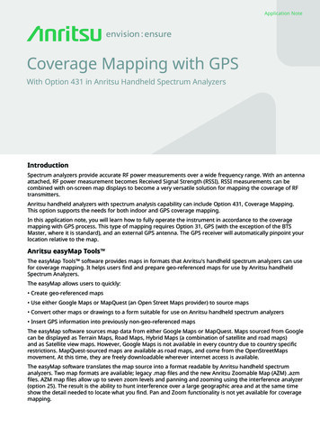
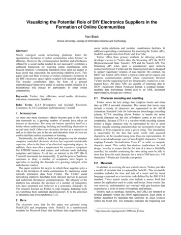
11.6Starter KitStarter Kit Interface UnitThe Starter Kit interface unit consists of a Lassen iQ GPS moduleattached to an interface motherboard, housed in a sturdy metalenclosure. This packaging simplifies testing and evaluation of themodule by providing two RS-232 serial interfaces which arecompatible with most PC communication ports. Power (9-32 VDC) issupplied through the power connector on the front of the interfaceunit. The motherboard features a switching power supply whichconverts this voltage input to the 3.3 volts required by the module. Thetwo DB9 connectors allow for easy connection to a PC serial portusing the serial interface cable provided in the Starter Kit. The metalenclosure protects the module and the motherboard for testing outsideof the laboratory environment.The Lassen iQ GPS receiver is a single module encased in a sturdymetal enclosure. The dimensions of the receiver in this enclosure are26 mm H x 26 mm L x 6 mm H (1.02” W x 1.02” L x 0.24” H). Astraight-in, panel-mount RF connector (J1) supports the GPS antennaconnection. The center conductor of the coaxial connector alsosupplies 3.3 VDC for the Low Noise Amplifier of the active antenna.An 8-pin (2x4), 0.09 inch header (J2) supports the two serial interfaces(CMOS TTL level), the pulse-per-second (PPS) signal (CMOS TTLlevel), and the input power ( 3.3 VDC). Figure 1.1 illustrates themodule in the metal enclosure.8Lassen iQ GPS Receiver
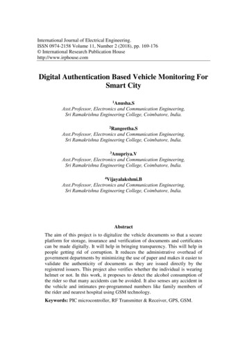
Starter KitBottom ShieldFigure 1.11Top ShieldLassen iQ GPS receiver ModuleThe interface motherboard includes a 9 to 32 VDC switching powersupply which provides regulated 3.3 VDC power to the receiver, andcontains circuitry which provides two RS-232 interface ports. A 3.6Vlithium backup battery enables quick hot starts. The TTL level PPS isbrought directly out to Pin 9 of the Port 2 DB9 connector on the frontof the interface unit.The Starter Kit includes an AC/DC converter for powering the modulefrom an AC wall socket. The metal enclosure (see Figure 1.2.)provides 2 DB9 interface port connectors, an antenna connector, and apower connector. Port 1 and Port 2 are used for serial I/O.Lassen iQ GPS Receiver9
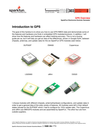
1Starter KitThe mounting plate is secured to the metal enclosure with four screws.The eight pin I/O header on the receiver module connects to a matingconnector on a ribbon cable. The ribbon cable is attached to a matingI/O connector on the interface motherboard. Figure 1.2 illustrates theStarter Kit interface unit.Port 2Figure 1.210Starter Kit Interface UnitLassen iQ GPS ReceiverPort 1
Starter Kit1.6.11Serial Port InterfaceThe Starter Kit interface unit is a DCE (Data CommunicationEquipment) device. To connect to a host computer, or DTE (DataTerminal Equipment) device, use a straight through cable. To connecta Differential Radio (DCE device) to the receiver (DCE Device) use across over cable or null modem cable.Table 1.2Port 1 able 1.3Port 2 PinoutsPinDescription1NC2TX3RX4NC5GND6NC7NC8NC9PPS OutLassen iQ GPS Receiver11
11.6.2Starter KitPulse-Per-Second (PPS)The Lassen iQ GPS receiver provides a four microsecond wide,CMOS compatible TTL level Pulse-Per-Second (PPS). The PPS is apositive pulse available on pin 9 of the port 2 DB9 connector of theinterface unit (see Table 1.3). The rising edge of the PPS pulse issynchronized with respect to UTC. The timing accuracy is 50nanoseconds when valid position fixes are being reported.The rising edge of the pulse is typically less than 20 nanoseconds. Thedistributed impedance of the attached signal line and input circuit canaffect the pulse shape and rise time. The PPS can drive a load up to5mA without damaging the module. The falling edge of the pulseshould not be used. The PPS is always on (early PPS) and is driven bythe Real Time Clock (RTC) until the receiver acquires GPS time fromthe satellite and generates position fixes. The PPS is outputimmediately after main power is applied, and continues even if thereceiver loses GPS lock. The drift of the PPS, when the receiver is nottracking satellites, is unspecified and should not be used forsynchronization.Note – Trimble has measured better than 50 nanosecond accuracy onthe Lassen iQ GPS receiver’s PPS signal in static mode. For moreinformation on use of the Lassen iQ GPS receiver in timingapplications, contact your Trimble sales representative.12Lassen iQ GPS Receiver
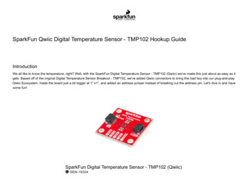
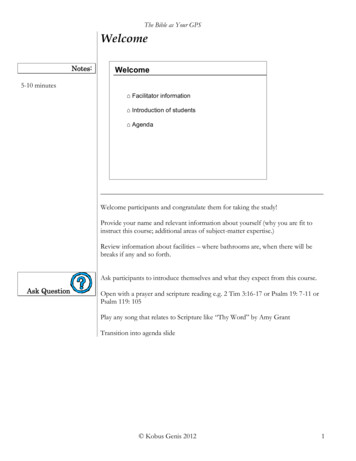
Starter Kit1.71PowerThe Lassen iQ GPS receiver receiver is designed for embeddedapplications and requires a regulated 3.3 VDC input ( 3.0 to 3.6VDC). The receiver provided in the Starter Kit is installed on amotherboard, providing a DC power regulator which converts a 9 to32 VDC input to the regulated 3.3 VDC required by the receiver.Power can be applied to the interface unit using one of three options:the DC power cable (Figure 1.3), the AC/DC power converter(Figure 1.4), or the cigarette lighter adapter.Figure 1.3DC Power CableThe DC power cable is ideal for bench-top or automotive testingenvironments. The power cable is terminated at one end with a 3-pinplastic connector which mates with the power connector on the metalenclosure. The un-terminated end of the cable provides easyconnection to a DC power supply. Connect the red power lead to asource of DC positive 9 to 32 VDC, and connect the black powerlead to ground. This connection supplies power to both the receiverand the antenna.Note – To ensure compliance with CE conducted emissionsrequirements when using the DC power cable, the Starter Kit interfaceunit must be bonded to a ground plane.Note – The yellow wire of the DC power cable is not used. Batteryback-up power is provided by a factory installed 3.6V lithium batteryon the motherboard.Lassen iQ GPS Receiver13
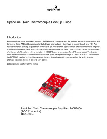
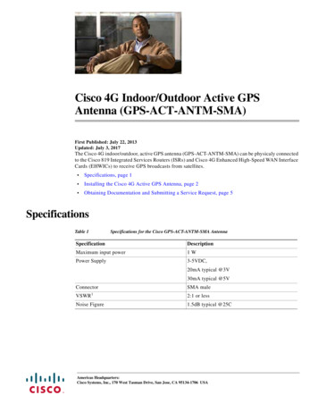
1Starter KitThe AC/DC power converter may be used as an alternate power sourcefor the interface unit. The AC/DC power converter converts 110 or 220VAC to a regulated 12 VDC compatible with the interface unit. TheAC/DC power converter output cable is terminated with a 3-pinconnector compatible with the power connector on the metalenclosure. The AC power cable is not provided in the kit, since thiscable is country-specific. The input connector is a standard 3-prongconnector used on many desktop PCs.Figure 1.414Lassen iQ GPS ReceiverAC/DC Power Converter
Starter Kit1.81Hardware SetupThe Lassen iQ GPS receiver supports the TSIP and NMEA protocols.A single port supports both the input/output of TSIP messages and theoutput of NMEA messages. Follow the steps below to setup the StarterKit interface unit. Figure 1.5 illustrates the setup.PowerSupplyLassen iQ GPSStarter KitGPSReceiver9 to 32 VDCDTEDCEComputerDCEGPSAntennaFigure 1.5Starter Kit Interface UnitLassen iQ GPS Receiver15
1Starter Kit1.For use with the TSIP or TAIP protocols, connect one end of the9-pin serial interface cable to Port 1 (or Port 2 to view NMEAdata) of the receiver module. Connect the other end of the cableto COM1 or COM2 on a PC. If your PC has a 25-pincommunication port, a 9-pin-to-25-pin adapter may be requiredfor this serial interface connection.2.Connect the antenna cable to the interface unit. This connectionis made by pushing the antenna cable connector onto the MCXconnector on the module. Place the antenna so that it has a clearview of the sky.Note – To remove the antenna cable, grasp the antenna mating MCXconnector and pull from the MCX connector mounted on the interfaceunit.3.Using either the DC power cable or an AC/DC power converter,connect to the 3-pin power connector on the interface unit.–DC Power Cable — connect the terminated end of thepower cable to the power connector on the interface unit.Connect the red lead to DC positive voltage ( 9 to 32VDC) and black power lead to DC ground. The yellowwire is not used. Switch on the DC power source.–AC/DC Power Converter — connect the output cable of theconverter to the 3-pin power connector on the interfaceunit. Using the appropriate 3-prong AC power cable (notprovided), connect the converter to an AC wall socket (110VAC or 220 VAC). The AC power cable is not provided inthe Starter Kit.Warning – If the Lassen iQ GPS Starter Kit is powered-up and attached toa PC COM port, the Windows operating system may recognize the StarterKit as a new serial device and assign it to the mouse driver. This cancause erratic mouse control. To disable serial mouse detection at start-up,add one of the following lines in the BOOT.INI file in the root directory:/NOSERIALMICE (detection is disabled on all serial ports) or/NOSERIALMICE COMx,COMy,COMz (detection is disabled on one ormore specified com ports)16Lassen iQ GPS Receiver
Starter Kit1.91Software ToolkitThe CD provided in the Starter Kit contains the iQ Monitor, theiQ CHAT, and the GPSSK interface programs used to monitor GPSperformance and to assist system integrators in developing a softwareinterface for the GPS module. These applications are described indetail in Appendix B, TSIP User's Guide.iQ Monitor runs on the Windows 95/98/2000/XP platforms.iQ CHAT runs under the DOS operating system on a 386 or higherprocessor.Following are quick start instructions for using the iQ Monitorapplication to monitor the receiver’s performance.1.Connect one end of the serial interface cable to Port 1 of theinterface unit. Connect the other end of the cable to the COMport of your PC.2.Turn on the DC power source or plug in the AC/DC converter.3.Insert the CD in the computer’s CD-ROM drive.4.The iQ Monitor program may be run directly off the CD or itmay be copied onto your computer’s hard drive. To run theprogram off the CD, initiate the iQ Monitor.exe file.5.When the iQ Monitor screen appears, the TX and RXindicators appear in the lower left corner of the status bar. Ablinking TX indicates that the PC is transmitting commands tothe receiver; a blinking RX indicates that the PC is receivingreports from the receiver. If either of these indicators stopblinking, there is no activity. The PC COM port settings a
Sunnyvale, CA 94088-3642 U.S.A. Phone: 1-408-481-8940, 1-800-545-7762 Fax: 1-408-481-7744 www.trimble.com Support Offices Trimble Navigation Limited Components Technologies Division 749 North Mary Avenue Post Office Box 3642 Sunnyvale, CA 94088-3642 U.S.A. Phone: 1-408-481-8940, 1-800-545-7762 Fax: 1-408-481-7744 Trimble Navigation Europe .