Transcription
CERAMIC TILE INSTITUTE OF AMERICA, INC.12061 Jefferson Blvd., Culver City, CA 90230-6219Phone (310) 574-7800 * Fax: (310) 821-4655 * Email: ctioa@earthlink.netFed. I.D. #95-4401962www.ctioa.orgwww.thetiledoctor.comCTIOA REPORT 2011-4-11SUBJECT: POOL TILE INSTALLATIONINTRODUCTIONThe purpose of this report is to explorethe current options for installing tile onconcrete (gunite, shotcrete, cast inplace concrete and cinder block)swimming pools, spas and other similarwater features as well as discuss theissues the industry experiences as theresult of the many types of tiles,installation materials and methodsbeing used in these assemblies.It is not the intent of this report toexplore the concerns of installing tile onsubstrates such as fiberglass, stainlesssteel and other substrates at this time,however, we are likely include moreinformation on these types of tileinstallations in the future.Pool tile installations can range fromsimple water lines, steps, infinity edges,all tile spas, all the way to tiling an entirepool. This report will explore all of theabove in order to develop acomprehensive list of best practices forinstalling tile on these types of waterfeatures.Because of the wide variety of materialsavailable in today’s market, the authorswere asked to explore the availableoptions in a non- proprietary mannerout of respect for the CTIOA Inc.Technical Committee and the industriesit serves.Table of Contents1)Evaluating the structure, or shell.2)Tile / Coping interface3)Surface Preparation4)Waterproofing5)Scratch coat and Floating6)Tile selection7)Installation8)Appropriate cure time and poolstart up considerations9)Short termmaintenance10)andlongtermPool water chemistryPool Tile CommitteeApril 11, 2011Page 1 of 17
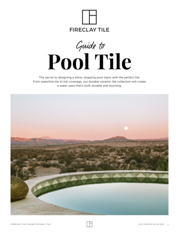
11)Glossary of termsEVALUATING THE STRUCTURETILE / COPING INTERFACE1)Pool coping comes in a variety shapes,forms, and designs, including thefollowing:Check the overall integrity of thestructure. Some of the more typicalcommon warning signs would be inthe order of structural cracks,exposed re-bar, out of level or lowbond beam.2)Observe surrounding landscapeand hardscape to make sure propermeasures have been taken toprovidemovementprovisionsbetween the decking and waterfeature shells.3)Observe any water or moistureentering the pool from an outsidesource through the shell, which maybe an indication of Closeinspection of the wall between thepool and catch basin is essential.Due to its free standing nature,these areas may exhibit signs ofinternal voids and corrosion ofstructural steel if the concrete,shotcrete, or gunite is not properlyshot or cast.Verify that the pool has beenengineeredandbuiltinaccordance with local regulations,according to soils reports, and watertable fluctuations have been takeninto consideration.Note: This is the responsibility of thepool contractor.Cantilevered concrete deckingA concrete deck around the poolspanning over the bond beam andwaterline tile in a manner allowingthe deck to “slip” back and forth asneeded.Thisisusuallyaccomplished with a trowelablemembrane, #15 felt paper, 6mil.Plastic or equal. A movement joint isthen placed between the copingand the top of the pool tile.IsolationSheet2)Cast in place concrete coping:Concrete coping formed on top ofa bond beam, extending over theedge of a pool by 2” to 3” andgenerally terminates in line with theback of the bond beam. Anyconcrete sub-base or decking thatbutts up to the coping and / or poolPool Tile CommitteeApril 11, 2011Page 2 of 17
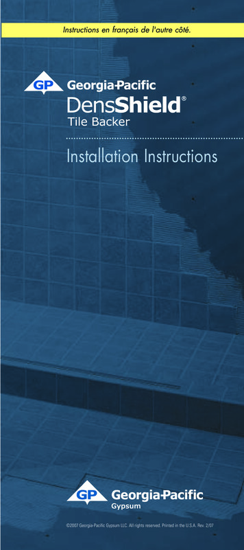
shell must have an expansionprovision between the two.Sealant4)Isolation Sheet(Optional)3)Quarried Stone Coping: Stone ofvarious species, sizes, shapes andthickness installed onto the top ofthe bond beam.Pre-Cast Coping: This coping isgenerally cast into molds off-siteusing concrete or pressed clay,allowed to cure and then broughtto the site for installation. It’s madein straight pieces, end caps, ondedMortarIsolationJoint5)Mechanically Fastened Coping:Commonly used in Rim Flow andSlot drain pools, This type of copingis generally attached by fasteners tostructural systems spanning over atrough designed for water to flowPool Tile CommitteeApril 11, 2011Page 3 of 17
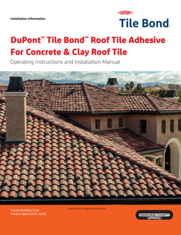
into. The coping is flush with thedecking and the top of the tile,allowing a slot of ¼” to ½” in widthfor water flow.Sealantbondbeamswithoutputtingpressure on waterline tile. If thebond beam of a pool is set too lowfor this to occur, it must be raisedand bonded mechanically orchemically to the existing bondbeam, bringing it up to the sameplane as the top of the waterlinetile. A movement joint must beplaced between the top of the tileand the bottom of the coping.Slot Drain2)IsolationJointIt’s important to have movementprovisions between the top of thewaterline tile and the bottom of thecoping. Equally important is to havethe back side of the copingterminate at the back side of thepool structure, placing movementprovisions between this area andthe any decking that abuts to it.Coping Placement Overview:Note: The interface of coping and tileas they relate to the bond beam ofpools and adjoining decking behindthem can account for a significantpercentage of pool tile failures wheninstalled improperly. These failures areoften a result of pressure applied to thepool shell, coping, and / or tile, frompool decking, and adjoining structures.The following are a few key points tokeep in mind when installing coping:1)Cantilevered decking must befree to slide over the top of poolCast in place coping must beplaced over a bond beam that ison the same plane as the top of thewaterline tile. It should be eithermechanically or chemically bondedto the bond beam unless the intentis to have it float freely on top of thebond beam.3)Pre-Cast coping and quarriedstone must have a positive bond tothe bond beam of the pool. Apositive bond can be achieved intwo ways:a) Thin-set installation: Pre float thebond beam by bonding the mortarwith cement slurry or 1/8”of modifiedthin-set. The coping can then beinstalled over the cured mortar bedusing a medium bed thin-set appliedPool Tile CommitteeApril 11, 2011Page 4 of 17
to the mortar bed and the bottom ofthe coping.b) Mud set installation: Apply cementslurry or 1/8” modified thin-set to thebond beam, followed by a mortarbed. The coping should then beback buttered with cement slurry or1/8” modified thin-set, placed intothe mortar bed and tapped intoplace.removed from the pool, the followingprotocol should be followed:1)Inspect the structure for any highareas in need of chipping, grindingor bush hammering and lower asneeded.2)Inspect all pipe penetrations, lightniches and any other penetrationscoming into the shell of the poolwhere tile is to be installed. Use alight chipping hammer to carefullychip all debris from around pipesandlights,payingparticularattention to any cavities in theseareas. Typically, large penetrationssuch as lights and large pipes willhave some degree of slump duringthe application of shotcrete orgunite, leaving voids underneaththem. This condition as well asinconsistencies around smaller pipescan lead to leaks if not addressedduring this stage of preparation.3)Clean the entire surface of thepool in order to remove any and allof the aforementioned impurities.Listed below are some of themethods, which will vary dependingon the condition of the surface.SURFACE PREPARATIONPreparation and cleaning: Concretepool shells are rarely smooth, free ofcontamination and defects, and aregenerally insufficient for the directapplication of waterproofing or tilewithout proper surface preparation.Proper preparation and cleaning of allsurfaces to be tiled is imperative to asuccessful installation.For cast in place concrete, all surfacesmust be inspected for remnants of formrelease agents or curing compounds aswell as surface defects such ashoneycombing and laitance, etc. Theseconditions can also be present on freestanding walls typically found invanishing edge pools in which a formwas used as a backstop to shoot guniteor shotcrete against.Concrete pool shells are also subject tosurface defects such as dusting, crazingand laitance from improper finishing, aswell as outside construction debris anddirt ground into the pool throughout thecourse of construction.Once all construction debris, dirt andfree standing water have beena)Lowpressurewashing/scrubbing(gardenhose with pressure nozzle)b)Acid cleaning followed bya neutralizer and rinsing withclean water.c)Sand blastingPool Tile CommitteeApril 11, 2011Page 5 of 17
d)Grindinge)Highpressurecleaning (1000 psi)waterf)Highpressurewaterblasting (5000 to 8000 psi)Once the pool is prepared, washedand allowed to become “saturatedsurface dry”, it’s ready to start fillingany large voids in the shell andaroundallpenetrationswithhydraulic cement. Caution must betaken to allow enough room aroundall pipes for the installation of fittingslater.WATERPROOFINGPool waterproofing falls into severalcategories, all of which can be veryeffective depending on a variety ofconditions the pool may be subjectedto, as well as the level at which the poolis expected to perform. While properlywaterproofed vessels will far exceed theindustry standard for in ground pools,there are conditions in which somesystems will be superior for a variety ofreasons including the following:1) Partially or fully above ground poolsand fountains. This could includehillside pools that are exposedunderneath.2) Structures that may be subjected tomovement. i.e. cold joints, concreteblocks,3) Pools in close proximity to orparticularly above occupied space,garages, or other similar areasAdditionally, extreme conditions mayrequiremultiple systemsusedtogether.An example is a pool in which anelastomeric system is specified, but thearea in which the pool is builtexperiences hydro-static pressure, fromthe negative side, stronger than theelastomeric system would be capableof sustaining. This is a case in which acementitious waterproofing capable ofholding back hydro-static pressurecould be applied to the pool shell priorto the application of the mortar bed inwhich the elastomeric system will beapplied.Some of the most common systems areas nesOneexample would be a sheetmembraneplacedintotheexcavated area prior to actuallyshooting the pool. This method istypicallyusedwhenextremeexternal or negative hydrostaticpressure is present. This would beused in conjunction with anothersystem inside the pool to keepwater from entering the shell.b)Integral crystallization - Anadditive mixed into the concrete ormortar that promotes crystallinegrowth that ultimately blocks thecapillaries in the cement.c)Topicallyappliedcrystallization – This uses the sameprinciple as the integral but isPool Tile CommitteeApril 11, 2011Page 6 of 17
applied to the surface of theconcrete shell. The concrete mustbe saturated and allowed tobecome saturated surface drybefore the cement paste is applied,at which time the crystals areactivated and will grow into theconcrete as far as moisture ispresent.Note: During the process ofcrystalline growth, residual crystalscan accumulate on the surfaceand act as a bond breaker forsubsequent layers waterproofing orotherbondingmaterials.It’simperative to remove all potentialcontaminantspriortotheapplication of additional material.d)Dense cementitious film- Aprepackaged cement powder thatwhen mixed with water or acrylic,depending on the manufacturers’recommendations, can be appliedto the surface of the concrete shelland will cure into a dense filmcapable of holding back moisture.e)ElastomericmembraneUsually latex based, these systemsare typically applied over a curedmortar bed and have flexiblecharacteristics. Once applied andcured, tile can be installed directlyover them with an approved thinset.f)FlexiblecementitiousSimilar to the elastomeric system buta two-part cement/latex basedwaterproofing. This system can beapplied directly over the shell andfloated over by bonding the mortarwith an approved thin-set orapplied over a cured mortar bed.Tile can then be bonded directly toit with an approved thin-set.WATERPROOF APPLICATIONSWaterproof applicationswillvarysignificantly depending on the type ofsystem being used as well as specificmanufacturers’ recommendations for agiven product. While it’s extremelyimportant to follow all of themanufacturers’instructions,thefollowing are some basic guidelines andareas of importance.1)CementitioussystemsWhenapplying any type of cementitiouswaterproofinginwhichit’srecommended to wet the substrate,always allow the surface to becomesaturated surface dry (damp withno puddles, or moisture glistening onthe surface) prior to application.Failing to do so will inhibit theproduct from achieving a properbond to the substrate.2)Subsequent bonding lines- Inmultipleapplications,eachapplication is considered a bondingline and should be treated as suchin order to achieve positive bondsthroughout all applications.3)Continually observe pool for anysigns of moisture coming throughthe shell from an outside source. Inthe case of such an occurrence,the source of moisture migrationshould be sought out and stoppedPool Tile CommitteeApril 11, 2011Page 7 of 17
before continuing any furtherapplication of waterproofing.4)As mentioned under “SurfacePreparation” in subsection #2,attention to pipe penetrations andlight niches is of upmost importance.Recognized as one of the most likelysources of leaks in a pool shell, allvoids around these penetrationsshould be tightly packed withhydraulic cement.As an added measure, pipe flangescan be considered where applicable.Scratch coat (if applicable) and floatcoatThe following materials and suggestedapplications apply to traditional mortarsystems.Manufacturers of some waterproofsystems may require specific mortarsystems that are more specificallydesigned to perform in conjunction withtheir waterproofing.Intheeventthataspecificwaterproofing system is e these recommendations.MaterialsCement – Portland cement ASTM C150Sand – Washed Plaster Sand ASTM C144Lime – ASTM C206 Type S or ASTM C207Type SWater- PotableMortar RatiosMortar bed (pool bottom) – 1 partPortland cement, 4 to 5 parts dampsand by volume. When mixed withwater the mortar shall have suchconsistency that will allow greatestcompaction during tamping of themortar bed.Scratch coat and mortar bed (poolwalls and gutter) – 1 part Portlandcement, ½ part lime (optional) and 4parts sandNote: Mix ratios can vary depending onlocal materials.BONDING MATERIALS APPLICATION1) Bonding Materials (not to be used tobuild up substrates)2) Portland cement paste3) ANSI 118.1 Dry Set Portland CementMortar minimum 1/8”4) ANSI 118.4 Modified Latex-PortlandCement Mortar - minimum 1/8”Scratch coat and/or subsequentplumb scratch (if necessary forexcessive build up) A bondedscratch coat should be used anareas in which excessive build up isnecessary, or where the possibility ofthe float coat “sliding” is imminent.5) Float coat (walls) Uniform thicknessranging from ½” to ¾”.6) Float coat (floors) shall not exceed2” in thickness per lift withoutPool Tile CommitteeApril 11, 2011Page 8 of 17
approvalengineer.ofthearchitectorPOOL TILE SELECTIONINSTALLATIONIt is a tile’s physical properties thatdetermine its suitability for use in poolsand water features; not all tile should beinstalled in submerged applications.Historically, tile intended for submergedapplications was marketed as “pooltile” making the tile selection processfairly straightforward. In the diversifiedmodern tile market, products are lesslikely to be marketed for specificapplications.Itisthedesignprofessional, specifier, installer andowner’s responsibility to solicit tile etilemanufacturer’s responsibility to providethese recommendations.The following are some of the physicaltile properties manufacturers generallytakeintoconsiderationwhenevaluating a tile’s suitability forsubmerged applications: Water Absorption Freeze-Thaw Resistance Chemical Resistance tion) Thermal Shock ResistanceOnly tile that is recommended by themanufacturer, in writing, for use in pools,spas and water features should beinstalled in these locations.Strength1)Recognized Installation Methods ANSI A108.14, 15, & 162)Bonding Mortars - ANSI A118.1,118.4 & 118.33)Grouts – ANSI A118.6 StandardCement grouts (sanded & d & un-sanded).4)Movement joints – the CTIOAacknowledges ANSI A108.01.3.7 &A108.02.4.4 – 2005, as well as TCNAEJ-171 for the installation ofmovement provisions in waterfeatures. However, we recognizepools as being unique in that theygenerally offer two very differentsets of circumstances within theconfines of the same vessel; abovethe waterline and below thewaterline.A) Above the waterline: This wouldinclude all areas from the waterlineup to the interface of the coping orother dissimilar materials in whichindependent movement may takeplace. Also included in this categorywould be raised bond beams,feature walls and infinity edgespillways, as well as any other areawhere tile may be subjected toextreme temperature variations,freeze/thaw conditions, or daily wetand dry cycles.Pool Tile CommitteeApril 11, 2011Page 9 of 17
B) Below the waterline: all areas of apool tile that are continuallysubmerged. This may be anythingfrom the lower portion of a 6”waterline tile, step features, all theway to a fully clad pool spa orfountain.It is the opinion of thiscommittee that while provisionsbetween decks, copings, dissimilarmaterials and installations subject toindependent movement, extremetemperature changes, includingfreezethawcyclesrequiremovement provisions, movementprovisions are not always viable incontinuallysubmergedtileinstallations.In summary - It is not the intent of thiscommittee to dissuade the use of,or downplay the necessity ofproperly placed movement joints.We do however recognize that thecommontradepracticeofminimizing movement joints incontinually submerged installationsappears to be a viable option incomparison to its above the watercounterpart.Although this is the case with mostresidential pools, extremely largepools or commercial pools manytimes contain cold joints or workingexpansion jointsin order toaccommodate movement or multiday placement of concrete,Important to remember is that allexpansion, control, construction,cold, and seismic joints in thestructure must be honored andcontinue up through the tilework.As with any tile installation, theaforementioned standards, ANSIA108.01.3.7, A108.02.4.4 – 2005 andTCNA EJ-171 should be the primarypoint of reference for movementjoint considerations.It is theresponsibility of the architect,engineer or builder to specify typeof joint and show locations.Bydefault, the burden will fall on thetile contractor to discuss theseoptions with the owner or temperatures should be maintainedbetween 50 F and 90 F degreesthroughout the installation andcuring process. Keeping in mind thatlow humidity during hot conditionscan accelerate the curing typarameters should be verified withthe thinset and grout manufacturer.In the event of climatic fluctuationsbeyondgivenparameters,precautionary measures should betaken to protect the installation.Bonding and coverage of bondingmaterial to the back of the tile isessential in submerged applications.As stated in the TCNA handbook forthe installation of ceramic tile, “95%bond to the bonding surface to thetile is mandatory”.Troweling methods and open times ofthinset prior to placing tile.1) Trowel sizes will vary depending onthe type, size and thickness of the tilebeing used.Pool Tile CommitteeApril 11, 2011Page 10 of 17
2) While flattening out the ridges of anotched trowel prior to placement of alltiles is good practice in order toachieve 95% coverage to the back ofthe tiles, it’s imperative with glass tile ofall sizes, weather opaque, translucent,or transparent.3) Open times of thinset will varydepending of a variety of conditions,includingambienttemperature,humidity, and wind conditions to namea few. Additionally, manufacturer’sinstructions referring to open times willvary. It’s always best to proceedcautiously and check for “skimmingover” of thinset throughout the courseof the installation process and adjustperceived open time accordingly.b) Easy to adjust individual tiles oncethe paper is removed, assuming thepaper is removed while the thinset is stillpliable.Mounted assembliesa) Inability to remove film while thethinset is pliable for fear of breakingbond to the tile. Adjustments can bemade by cutting through the film;however, the installer is somewhatlimited to the amount of adjustmentsthat can be made as compared topaper face systems.b) Inability to remove thinset that haspushed up through the joints to theback side of the film until the film isremoved.a) Paper facedb) Clear film face mountedc) Back mounted with mesh.Differentiate between water solubleand water stable glue for mountingthe tile to the mesh. While we don’trecommend water soluble glue,performance of both is the burdenof the tile manufacturer and shouldbe stated in writing.d) Perforated paper back mountedtile. Not recommended by TCNAe) Edge mounted tileCommentary about the benefits anddrawback of each of the mountedassemblies.Paper face mounted assemblies:Benefits:a) 100% access to the bonding surfaceof the tile.Drawbacks:Requires an installer with a higher levelof experience than other mountedassemblies.Clear film face mounted assemblies:Benefits:100% access to the bonding surface ofthe tile.Good visibility of the installation throughthe clear film.Drawbacks:Back mounted assemblies:Benefits:Ease of installation as compared toface mounted assemblies, including thespeed at which sheets can be installedas well as the immediate access to theopen joints for the removal of excessthinset. Sheets can also be adjusted tosome degree without having to cutthrough mounting material.Pool Tile CommitteeApril 11, 2011Page 11 of 17
Drawbacks:WATER SANITATION SYSTEMSa) Limited access to the bondingsurface of the tile due to mesh andthe glue holding the mesh to the tile.b) Limitations to the maneuverability ofsheetswhilenegotiatingthecurvatures in pool bottoms and othertransition areas.I.Edge mounted assemblies:Benefits:Typically, good access to the bondingsurface of the tile.Ease of installationchallenging surfaces.onflat,non-Drawbacks:a) Limited ability to adjust sheets ornegotiate curvatures and transitionareas in pool bottoms.b) Edge mount material can sometimesencroach the surface of the tile tosomedegreeandultimatelyjeopardize the grout by leavinginconsistencies in its thickness.CURE TIME AND START UPCONSIDERATIONS1)Proper cure time minimum 21days after grouting & caulking, priorto fill.2)Keeping the pool covered duringthe curing process3)Flow rate of fill or emptying water1” per hour.4)Tests fill water prior to filling pool.IntroductionAs most tile surfaces have cementitiousgrout or polymer modified cementitiousgrout products in them, a proper waterchemistry regimen is essential for thelong-term durability of these products.This begins prior to filling the pool or spa,with tap water testing, and thencontinues with the long-term chemicalmaintenance of the pool, spa, or waterfeature.Prior to filling water features, the tap orfill water must be tested. The fill watershould be checked for pH, totalalkalinity, and calcium hardness. Tapwater should also be checked fordissolved metals. This is especially truefor well water.II.SummaryFill water with low calcium hardness, lowpH, and/or low carbonate alkalinitycoming in contact with cementitiousgrouts are capable of deteriorating thecementitious compounds of the grout.If the water is aggressive enough toleach calcium from the grout’s matrix orto break down cement compounds,then the problem must be identifiedand addressed after the pool is filled.The water must be brought up to theANSI/APSP standards for residential orcommercial pools as quickly as possibleto avoid short-term and long-termdurability issues.The Association of Pool and SpaProfessionals(APSP)idealwaterchemistry parameters for residentialpools:Pool Tile CommitteeApril 11, 2011Page 12 of 17
It is recommended that the pool waterchemistry be maintained using theLanglier Saturation Index (LSI).TABLE 1. ANSI/APSPThe APSP ideal LSI range is 0.0 to 0.5.PH7.4 – 7.6The National Plasterers Council’s (NPC)water chemistry parameters are similarto the Association of Pool and SpaProfessionals (APSP) standards, but withTotal Alkalinity80 – 120 ppmCalcium Hardness200 – 400 ppmStabilizer (CYA)30 – 50 ppmTABLE 2. NPCFree Chlorine2.0 – 4.0 ppmTDS1500 ppm greaterthan TDS at pool orspa start-up.PH7.2 – 7.6CarbonateAlkalinity80 – 120 ppmCalciumHardness200 – 400 ppmStabilizer or30 – 50 ppmCyanuric AcidFree Chlorine1 – 3 ppmTDS300 – 1800 ppmSalt2500 – 3500ppm (SaltChlorination SystemsOnly)The NPC recommends a LanglierSaturation Index (LSI) of 0.0 to 0.3 formaintenance of pool water. The reasoncarbonate alkalinity is used instead oftotal alkalinity or tested alkalinity is dueto the LSI using carbonate alkalinity onlyinitsmathematicalcalculations.Carbonate alkalinity is calculated bysubtracting a percentage of the pools’cyanuric acid content from the testedalkalinity, thus giving you a corrected orcarbonate alkalinity. (See AttachedTable K from the Taylor TechnologiesTest Kit Booklet)some differences:Two key factors found in the NPC DailyWater Chemistry and Maintenancesheet are no negative indices in the LSIand the use of carbonate alkalinity. If aLSI calculation produces a negativenumber, then the water is undersaturated and thus capable ofproducing a deleterious effect oncementitious materials and othermaterials used to construct pools.The NPC Swimming Pool Start-upProcedures sheet recommends that nosalt (NaCL) be added to the pool or spawater for at least 28 days. The logicbehind this waiting period is to allow thepools’ cementitious materials to hydrateor mature without the presence ofsodium chloride affecting the newhydration products that are rapidlyforming in this early stage of curing.Pool Tile CommitteeApril 11, 2011Page 13 of 17
Tile grout, being cementitious, is alsodeveloping strength during this initial 28dayperiodsothesamerecommendations for introducing saltshould also be followed as a prudentmeasure.If the presence of metals or a highmineral content is discovered during theinitial tap or fill water testing, then theuse of a sequestering agent isrecommended. Follow sequesteringagent manufacturers’ directions as tothe proper initial dosage and then themaintenance dosage to preventstaining and mineral precipitation issues.III.ConclusionMost pool surfacing materials will beaffected in both the short and longterm by the water if it is not maintainedto the appropriate standards. Fromdissolution of the grout by aggressivewaterstostainingandmineralprecipitation, properly balanced wateris an essential requirement for thecosmetic and long-term durability of alltiled water features. If the water is notkept balanced, long-term damagesmay also occur to the bondingmaterialsfloatingmaterials,waterproofing and even the tile itself.GLOSSARY OF TERMSTerminologyAcid Washing - 1. The cleansing of theplaster surface, through controlleddissolution of the material on acementitious coating’s surface toremove efflorescence, dirt or otherunwanted stains. 2. The process ofetching of a cementitious coating’ssurface in order to expose theaggregated or sand to create theexposed aggregate finish. 3. A lowstrength (diluted) acidic solution usedfor removing certain cementitioussurface stains, dirt, precipitants, ormarks, whereby the stain is removedwhile little, if any, of the cementitioussurface has been compromised.Admixture - Any material, other thanthe cement, aggregate, sand, and/orwater, that is added to the mix design,whether as a pre-blend or as anindividual constituent added at thejobsite.Aggregate - 1. The inert granular portionof a mix design that is typically refined,sized, graded, and/or apportioned tomaximize a cementitious coating’sphysical and aesthetic characteristics.2. The sand, rock, or stone portion of themix design.Balanced Water Chemistry – 1. TheNational Plasterers Council considers“balanced” water chemistry to beswimming pool water kept in such amanner so as to maintain a chemicalcondition of a water that is within anideal range that is: a) within theapproved ANSI/APSP ideal levels [seeANSI/APSP-1 Standard. Appendix A]and, b) constantly carrying a sufficientbuffer so as to minimize the water’stendency to erode, etch, or otherwisedeteriorate the cementitious coating. 2The process of ensuring that a water’spH, carbonate alkalinity, total alkalinity,Pool Tile CommitteeApril 11, 2011Page 14 of 17
hardness, total dissolved solids, andchlorine content, is being monitoredand maintained to be constantly withinan ideal range (or “balance”).Bond (Adhesion) – 1. The ability of ahardened cementitious coat to holdtogether with the substrate or to apreviouscementitiouscoatbymolecular forces, interlocking action, orboth.Bond (Chemical) – The ability to holdtogether, by chemical process, whetherby adhesive or cohesive bond.Bond (Cohesion) – 1. The ability of afresh plaster mixture to hold togetherduring application and for the mixtureto remain inter-mixed during thepumping,placingandfinishingprocesses.Bond (Mechanical) – The ability of aplaster coat to key into, embed with, orotherwise lock together with a plasterunder-coat or a substrate.Bond Failure – 1. The failure of thecementitious coating to hold together.2. The failure of the cementitiouscoating to remain adhered to theunderlying s
Pool Tile Committee April 11, 2011 Page 1 of 17 CERAMIC TILE INSTITUTE OF AMERICA, INC. 12061 Jefferson Blvd., Culver City, CA 90230-6219 Phone (310) 574-7800 * Fax: (310) 821-4655 * Email: ctioa@earthlink.net Fed. I.D. #95-4401962 www.ctioa.org www.thetiledoctor.com CTIOA REPORT 2011-4-11 SUBJECT: POOL TILE INSTALLATION INTRODUCTION