Transcription
ALLWEILEROperating and Maintenance InstructionsVM No.:696.0005 GBEdition:05.99Ident No.:Screw pumpswith magnetic drive550 145Retainfor futureuse!Series SN.AR. and SM.AR.Design GM.Order no.:Pump ident. no.:Machine no.:Pump type:Operating data of pump as per order data sheetDimensions as per order dimension drawingPersons with aPacemakermust not installservice or operatethe pump!Contents1. GeneralThese Operating and MaintenanceInstructions contain information fromthe pump manufacturer. They may needto be supplemented by instructions ofthe operator company for its personnel.These instructions do not take accountof specific information relating to operation and maintenance of the processplant into which the pump is integrated.Such information can only be given bythe persons responsible for construction and planning of the plant (plantmanufacturer).Such specific instructions relating tooperation and maintenance of theprocess plant into which the pump isintegrated have priority over theinstructions of the pump manufacturer.2. Safety3. Transportation andIntermediate Storage4. Description5. Installation/Mounting6. Start–up/Shutdown7. Maintenance/Repair8. Operating Faults, Causesand Remedial ActionRefer to the operating instructions ofthe plant manufacturer!9. Associated Documentation1
SN.AR. / SM.AR.1General1.1AbbreviationThe abbreviation of the screw pump is set up accordingto the following schema, and is engraved on the typeplate.ALLWEILER1.2Application and range of utilizationThe inside–bearing screw pumps of type seriesSN.AR.GM. and SM.AR.GM. are three–screw,rotary positive displacement pumps for lubricatingliquids which – because of certain characteristicfeatures (e.g. toxic, malodorous, detrimental to health)– call for the service of pumps without shaft seal.The liquids must not contain any abrasive particles norchemically attack the pump/magnetic drive materials.Due to a modular system, the pumps may be designedas cartridge–unit pumps, horizontal foot–mountedpumps, flange–mounted pumps as well as verticalplinth–mounted pumps.1.3Performance dataThe exact performance data applicable to the pumpcan be taken from the order data sheet and/oracceptance test report, and are engraved on the nameplate.The pressure data indicated there apply only toapproximated static pressure load. In the case ofdynamic alternating pressure load, consult themanufacturer.1.4WarrantyOur warranty for shortcomings in the supply is laiddown in our delivery conditions. No liability will beundertaken for damages caused by non–compliancewith the operating instructions and service conditions.If at any later date the operating conditions change (e.g.different fluid conveyed, speed, viscosity, temperatureor supply conditions), it must be checked by us fromcase to case and confirmed, if necessary, that the pumpis suited for those purposes. Where no specialagreements were made, pumps supplied by us may,during the warranty period, only be opened or varied byus or our authorized contract service workshops;otherwise our liability for any defects will cease.1.5TestingPrior to leaving our factory, all pumps are subjected to athorough test run and performance test on the teststand. Only properly operating pumps, achieving theperformance assured by us, leave the factory.Thus, compliance with the following operatinginstructions ensures fault–free operation and fulldelivery.1.6AvailabilityAs a matter of principle, we recommend stockingreplacement pumps and withdrawable units (hydraulicaction system) where the supplied pumps are adecisive factor in maintaining a production or deliveryprocess. In this way downtimes can be avoided, orreduced to a minimum.Example:SeriesSN H 40 A R 46 GM 1-. E – W.Type seriesSN Low pressureSM Medium pressureDesignH Horizontal foot pumpGH Horizontal foot pumpEF Cartridge–unit pump forH and GH pumps Flange pumpGF Flange pumpS Plinth pumpGS Plinth pumpEF Cartridge–unit pump forF, GF, S and GS pumpsSize theoretic delivery in [l/min]with normal pitch and1450 1/minType of driving spindleDirection of screw pitchRL right (serial design) leftAngle of screw pitch [degrees]Special design featureGM Slide bearing Magnetic driveMagnetic drive sizeMagnets fitted(total length of magnets in cm)Casing heatingEPXY Heating bars, electricHeating cartridge for steam or heat carrierHeating shell for steam or heat carrierDouble shell for steam or heat carrierMaterial codeVM 696.0005 GB/05.99 – Ident–Nr. 550 1452
SN.AR. / SM.AR.2ALLWEILERSafetyThese operating instructions contain basic tenance. It is therefore essential that they are readby fitters and all specialist staff and customer personnelprior to installation and start–up. They must always bekept at hand at the place of installation.2.3The special safety instructions contained in the otherchapters must be observed in addition to the generalsafety instructions in this chapter.2.1Dangers in the event of non–compliance withsafety instructionsFailure to comply with the safety instructions may resultin danger to persons, and place the environment andthe machine at risk. Non–compliance with the safetyinstructions will lead to the loss of any claims fordamages.Non–compliance may result in the following dangers:S Failure of important functions of the plantIdentification of safety instructions in theoperating manualThe safety instructions contained in these operatinginstructions which represent a danger to personnel ifnot complied with are specially marked by the generaldanger symbol:S Failure of specified methods for maintenance andservicingS Danger to persons resulting from electrical,mechanical and chemical effectsS Danger to the environment resulting from leakage ofhazardous substances2.4Responsible working practicesThe safety instructions contained in these operatinginstructions, current national accident preventionregulations, as well as internal working, operating andsafety rules of the customer, must be observed.2.5Safety instructions for the user/operatorWarning symbolas per DIN 4844–W9Warning of danger from electric voltage is indicated asfollows:S Hot or cold machine parts representing a dangermust be protected against accidental contact onsite.S Protection against accidental contact for movingparts (such as the coupling) must not be removedwhile the machine is in operation.Warning symbolas per DIN 4844–W8.S When operating pump aggregates in a dust–ladenenvironment (e.g. milling, chipboard manufacture,bakeries), the surfaces of the pumps and motorsmust be cleaned at regular intervals, depending onlocal conditions, in order to maintain the coolingeffect and eliminate the possibility of spontaneouscombustion. Please also see explosion protectionregulations (ZH 1/10).Instructions which are essential to avoid endangeringthe machine and its operation are marked by the wordATTENTIONInstructions affixed directly to the machine such asS Leakage (e.g. from the shaft seal) of hazardoussubstances being handled, such as explosive, toxicor hot materials, must be discharged in such a waythat no danger to persons or the environment iscreated. Legal regulations must be observed.S Directional markersS Signs for fluid connectionsmust always be observed and maintained in fullylegible condition at all times.2.2S Dangers from electrical energy must be eliminated.For details in this regard, please refer to VDE andlocal power company regulations.Personnel qualification and trainingThe operating, maintenance, inspection and mountingpersonnel must be appropriately qualified for the dutiesassigned to them. The scope of their responsibilities,competency and supervisory duties must be closelycontrolled by the customer. If the personnel do not havethe required knowledge, they must be trained andinstructed. If required, this may be provided by themanufacturer/supplier on behalf of the customer. Thecustomer must additionally ensure that personnel fullyunderstand the content of the operating instructions.VM 696.0005 GB/05.99 – Ident–Nr. 550 1453
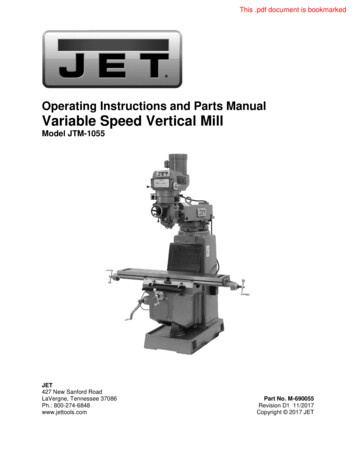
SN.AR. / SM.AR.2.62.72.8ALLWEILERSafety instructions for maintenance, inspectionand installationThe operating company must ensure that allmaintenance, inspection and installation tasks areperformed by authorized and qualified specialistpersonnel who have thoroughly studied the operatinginstructions.Work on the machine is only to be carried out when themachine is at a standstill. The procedure for shuttingdown the machine described in the operatinginstructions must always be followed.Pumps or aggregates handling fluids which aredetrimental to health must be decontaminated. Allsafety and protective devices must immediately berefitted and made operational on completion of thework.The instructions under Section 6.1, ”Preparation forstart–up”, must be observed before 1PackagingAttention must be paid to the markings on thepackaging.The suction and pressure sides and all auxiliaryconnections must always be closed duringtransportation and storage. The closing plugs must beremoved when the pump aggregate is installed.3.2TransportationThe pump or pump aggregate is to be safelytransported to the place of installation, if required bymeans of lifting gear.The generally applicable safety regulations forlifting loads must be observed. The crane deviceand cables must be adequately dimensioned. Thecables must not be attached to the attachment eyesof the motor.Unauthorized conversion and production ofreplacement partsConversion or modification of the machines is onlypermissible after consultation with the manufacturer.Original replacement parts and accessories approvedby the manufacturer are intrinsic to safe operation. Ifother parts are used the manufacturer cannot be heldliable for the consequences.Complete aggregates, with a base plate–mountedhorizontal foot pump and mounted, coupled motor,must be transported to the place of installation asshown in the illustration.Unacceptable modes of operationThe operational safety of the machine supplied is onlyensured when it is used in accordance with Section 1 ofthe operating instructions. The limit values given on thedata sheet must not be exceeded under anycircumstances.Fig. 1: Transportation of a horizontally mounted pumpaggregateIn the case of vertically and horizontally mountedflanged pump aggregates, it is advisable to attach thecables to the wall/foot lantern or intermediate fittinglantern (not shown).During transportation ensure that theaggregate is secured against topplingover. The attachment eyes of the motor can be used tosecure it.Transport damageCheck the pump for damage on receipt.Any damage detected must be notified immediately.VM 696.0005 GB/05.99 – Ident–Nr. 550 1454
SN.AR. / SM.AR.3.3Preservation and storage of the screw pumps3.3.1PreservationIn the case of storage or prolonged standstill, thepumps must be protected against corrosion. In thosecases, an outside and inside preservation is to beprovided. The durability of the protection againstcorrosion, which is limited in time, depends on thecomposition of the preservative to be applied and thestorage conditions.Under normal circumstances the pumpshave no special preservative.At an additional charge we can, however, supplypumps and replacement parts ex factory with a preservative adequate to the planned storage period.ALLWEILER3.3.1.4 DepreservationPrior to setting the pump in motion, the preservativeapplied must be removed.Environmentally compatible disposal must beensured.The preservative applied for inside preservation cannormally be removed by flushing the pump with the fluidto be conveyed.Alternative, suitable solvents may be applied forremoving the inside and outside preservation.Appropriate solvents are for example: petroleum,benzene, Diesel fuel, spirit, alkalis (industrial cleaners)or any other wax solvents. Steam jet cleaning deviceswith appropriate admixtures can also be used (allowwax solvent to act beforehand).We will be pleased to specify suitable preservatives foryou on request.Prior to start–up after prolonged storage,all elastomers (O–rings, shaft seals) mustbe checked for their elasticity of shape. Embrittledelastomers must be exchanged. Elastomers ofethylene–propylene rubber (EPDM) must always bereplaced. The pump must be filled with fluid to preventseizing of the components. A pressure–relief valveattached or fitted in the pipeline must be checked forpassage.Note: If on the plant side, the pipelines, (oil) tanks orother parts are wetted with paraffin–containingpreservative, the entire plant must be depreserved asparaffin is detrimental to the air separating capability ofoil. This may result in unsteady operation of the pumpand loud noise.3.3.1.1 Outside preservationThe outside preservative should be applied by paintingor spraying with a spray gun.Points of preservation:All bright and unvarnished parts (e.g. shaft ends, couplings, flange facings, valve and manometer connections).3.3.1.2 Inside preservationThe preservative is to be applied by filling the pump. Forthese purposes, the suction side of the pump must firstbe closed with a dummy flange. During filling, thepressure flange must be on a higher level than thesuction flange. During the filling process, the shaft mustbe slowly cranked against the direction of rotation.Filling must be continued until the preservative reachesthe sealing strip of the delivery flange, bubble–free.Then the outlet side is to be closed with a dummyflange.Note: Not required for pumps made of stainless materials.3.3.2Points of preservation:All bright parts inside the pump (e.g. pump casing inside, screw spindles, ball bearings, pressure–reliefvalves).3.3.1.3 Monitoring of preservationIn the event of prolonged storage, the preservation ofthe pump must be checked by the customer at regularintervals.Every six months the pump level must be checked; ifnecessary, preservative must be topped up to thesealing strip on the pressure flange.At the same time, the packing must be checked fordestruction, and repaired if necessary.Note: Liability for damages caused by improperpreservation cannot be assumed by us.VM 696.0005 GB/05.99 – Ident–Nr. 550 1455StorageDuring storage of the pump, the suction and outletbranches and all other supply and discharge branchesmust always be closed with dummy flanges or dummyplugs.Storage should be in a dry, dust–free room. Duringstorage, the pump should be cranked at least once amonth. During this process, parts such as the shaft andbearings should change their position.
SN.AR. / SM.AR.ALLWEILER4Description4.1Structural design4.1.1Screw pumpThree–screw pumps in horizontal and vertical designform, with a double–threaded driving spindle and twodouble–threaded idler spindles, enclosed in a housinginsert with narrow running clearance.The delivery elements are installed in a pump housingwhich is closed off on the drive side and the end side bypump caps.4.1.2.1 Bearing bracketThe driving shaft with the bolted–on outer magnet rotoris borne by a one–piece bearing bracket in amply dimensioned lifetime lubricated roller bearings. The lifetime lubrication is not harmful to the environment.4.1.2.2 Can/SealingRows of permanent magnets of alternating polarity arearranged on the outer magnet rotor which is supportedin roller bearings. Separated by the stationary can, theinner magnet rotor with matching magnet assembly fitsconcentrically into the outer magnet rotor. The can hermetically seals the rotor space exposed to the deliverymedium from the non–exposed driving part.4.1.1.1 Bearing and lubricationBy a medium–lubricated axial/radial silicon carbidecompact slide bearing.4.1.1.2 Pipeline and auxiliary connectionsFor execution, branch positions and dimensions of allconnections, see order–specific installation drawing.4.2Mode of operation4.2.1Screw pumpThrough the suction connection, the fluid is conveyedinto the suction chamber of the pump. From there thefluid flows into the spindle chambers, which areconstantly formed by the rotary motion at the spindleend on the suction side. By the translatory rotarymotion, the chambers filled with the fluid move from thesuction side to the outlet side. During this process theclosed chamber volume does not change. At thespindle end on the outlet side the chamber openstowards the delivery chamber. The fluid is steadilypushed out into the delivery chamber from where it istransported, through the pressure connection, into thepressure pipeline.The axial thrust acting on the faces of the profile flankson the outlet side is hydraulically balanced by anappropriate dimensioning of the compensating pistonof the driving spindles and the compensating journalsof the idler spindles. Thus the bearing is relieved of thehydraulic axial thrust.The idler spindles are hydraulically driven by means ofappropriate dimensioning of the spindles. Only thetorque resulting from the fluid friction is transmitted viathe profile flanks. They are therefore practicallystress–free, and not subject to any wear.As a result of the constant chamber volume the mediuminside the pump is transported, almost entirely free ofturbulence and squeezing, from the suction side to theoutlet side.The structural design and mode of operation of thescrew pump ensure a very low noise level and analmost pulsation–free delivery.4.2.2Magnetic driveThe torque is transmitted, without contact, from theprime mover onto the pump via the magnetic field linesbetween the outer and inner magnet rotors.By variation of the magnet assembly, the transmittedpower can be adapted to operational requirements.The magnet material is cobalt–samarium. In addition toa very high energy density, this material is also highlytemperature–resistant. In operation, the prime moverand the pump rotate at the same speed. This alsoapplies to the run–up and run–down phases.Overloading of the magnetic drive causes the outermagnet rotor to race. Briefly switching it off re–synchronizes it, and the pump can be restarted. Racing fora short time does not lead to demagnetization or damage the magnets.4.1.1.3 HeatingWhere heavy heating oils or other fluids which tend tosolidification when cooling are to be pumped, the following equipment is available for pump heating.Heatingelectricalwith steam or heat carrierSh t P––x–Y–––xÀ Only pumps of steel–welded construction are fitted with aheating jacket.For further details on pump heating and the necessaryheating capacity, refer to our specific brochure VM4.70/Z.–Nr. 6000002024.4.1.1.4 Pressure relief valveFor safety reasons, screw pumps must generally beequipped with a pressure relief valve.Most pumps are already equipped with a pressure reliefvalve when they leave the factory. The standard triggerpressure of this valve is approximately 10% above theoperating pressure.Pumps that are supplied without a pressure relief valvemust be provided with a suitable safety valve by thecustomer. The safety valve must be fitted in the discharge pipeline between the pump and the first shut–offdevice.4.1.2Magnetic driveThe magnetic drive is flanged onto the screw pump byway of an intermediate cover on the drive side. Thedriving spindle of the pump is rigidly connected to therotor of the magnetic drive by way of a driver–typefastening.VM 696.0005 GB/05.99 – Ident–Nr. 550 1456
SN.AR. / SM.AR.ALLWEILERThe magnets in the medium are encapsulated and thusprotected against any effects of the delivery medium.The heat dissipation within the magnetic drive is discharged by a fluid circulation device between the delivery and suction chambers.4.3Construction of the pump aggregate4.3.1DriveThe pumps can be directly coupled with electric motorsor any other prime movers.In most cases, surface–cooled three–phase squirrelcage induction motors are used as driving motors, typeIM B3 or IM V1, class of protection IP 54 to IECstandard, class B insulation, outputs and maindimensions to DIN 42 673 or 42 677.It must be ensured that the motor is balanced to the rated power of the magneticdrive. The magnetic drive may break away if the motorpower is too high.The exact motor data are to be found on the order datasheet.4.3.2(Driving–) Shaft coupling and contact protectionPower transmission is effected via a flexible coupling toDIN 740. Additional radial forces must not act on thedriving spindle.Protection against accidental protection to EN 809 isprovided where the product package comprises apump, base plate and shaft coupling, or where awall/foot lantern or intermediate fitting lantern issupplied as part of the product package.According to accident prevention regulations, thepump must only be operated with a protectionagainst accidental contact as per EN 809.If no contact protection is provided, it must be attachedby the operator.VM 696.0005 GB/05.99 – Ident–Nr. 550 14574.3.3Base plateHorizontal foot pumps are mounted with the drive motoron a common base plate. Base plates can be providedin cast or steel design.4.3.4Wall/foot lanternHorizontally or vertically mounted flange pumps areconnected to the drive motor by way of a wall/footlantern.4.3.5Fitting lanternFitting in fluid tanks is enabled by using fitting lanterns.4.3.6Motor lantern/intermediate lanternVertically mounted plinth pumps are connected to thedrive motor by way of a motor lantern or intermediatelantern. In the plinth pumps the end–side cover isexecuted as a round foot for vertical plinth mounting.
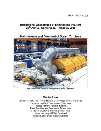
SN.AR. / SM.AR.5Installation/Mounting5.1InstallationThe pumps can be horizontally or vertically mounted.ALLWEILERBase �ÄÄÄÄÄÄÄÄÄÄÄÄÄÄÄÄÄÄÄFor safety reasons the ”downward–facing motor”arrangement is not permitted. 5.2 Steel shimsMode of fasteningThe mode of fastening is dependent on the design typeand size of the pump and the coupled motor, as well aslocal installation conditions.Foundation 750Fig. 2: Alignment with steel shimsHorizontal alignment of the aggregate is produced byway of flat–machined surfaces on the pump using amachine spirit level. Measurements are taken in longi–tudinal and transverse directions of the pump aggre–gate.Permissible deviation: max. 1 mm per 1 m length.Horizontal foot pumps are normally mounted with thedrive motor on a common base plate.Flange pumps can be fastened by means of a wall/footlantern, either horizontally or vertically, at the place ofinstallation.Vertical plinth pumps have a small installation area dueto their design, and can also be fastened on a concretefoundation or foundation frame.In the case of flange and insertion pumps which areinstalled in immersion bodies, tanks, cylinder housingsetc., the fixing flange of the pump, together with theflange contact surface, provides a fastening option inthe various executions.5.3.5Fixing the pump aggregateWhen the aggregate has been aligned on the founda–tion the fixing bolts should be tightened evenly, alter–nating side to side.Recommendation: As far as possible, the base plateshould be cast–on over its entire length with a non–shrinking mortar casting compound.Note: When casting–on and packing with the mortarcasting compound, it must be ensured that the baseplate makes contact with the foundation over its entirearea, and that there are no cavities.Precise details on form and dimensions are givenin the installation drawing.5.3Foundation5.4Checking the coupling alignment5.3.1GeneralThe foundation may be a floor/concrete base or a load–bearing steel foundation frame.Note: The foundation must be designed so it can takethe weight of the pump aggregate across its entire area.5.4.15.3.2Characteristiques of a steel foundation frameA steel foundation frame must be designed so that thebase plate makes contact across its entire area, andcan be bolted or welded down.If the base plate is only supported at fourpoints the pump aggregate will hang downin the middle. This will affect the alignment of the cou–pling and may also lead to severe noise being genera–ted.Checking the coupling alignment in case of horizontal setup on base plate (if used)A complete delivered pump aggregate has been care–fully assembled at the factory. After proper installation,and prior to start–up of the pump aggregate, the align–ment of the coupling must be checked.The check can be made with a straight–edge and afeeler gauge, or with other suitable equipment (such asa laser alignment device).5.3.35.3.4The measurements are taken in two planes, each offsetby 90 , on the circumference of the coupling.If a height, lateral or angle offset is detected betweenthe two coupling halves, the drive motor should be re–aligned such that the coupling halves are flush witheach other (level out with flat packing shims as neces–sary).Characteristiques of a floor/concrete foundationThe foundation must be horizontal, flat and clean, andbe capable of bearing the full load upon it.Note: Concrete foundations must be executed withstandard concrete of strength class B 25 as a minimum.The gap between the two coupling halves must be thesame all round the circumference of the coupling. Thespecified gap is shown in the installation diagram.Alignment of the pump aggregateThe pump aggregate must be aligned to its pre–setheight and system dimensions. This is done using sui–table steel shims, arranged directly adjacent to each fi–xing bolt.The total height of the steel shims is determined by thepre–set system dimensions of the plant. The steelshims and the base plate must sit flush.If the fixing holes are more than 750 mm apart, we re–commend fitting additional steel shims in the middle ofthe base plate.VM 696.0005 GB/05.99 – Ident–Nr. 550 145The spacing between the straight–edge laid over bothcoupling halves and the respective shaft must be thesame all round the circumference.8
SN.AR. / SM.AR.ALLWEILER5.5Assembly of pump and motorIf the aggregate is only assembled at the place of use,the coupling is assembled as follows:1. Coat the pump and motor shaft ends with a fine filmof molybdenum disulfide (e.g. Molykote) and insertkeys.Straight–edge2. Push on the coupling halves on the pump and motorside with the aid of a pusher device until the shaftend is flush to the coupling hub.If no puller is available, heating the coupling halvesto approx. 100 C (without rubber buffer) facilitatespushing.Impacts to the components of the pumpor motor must be avoided.Feeler gaugeFig. 3: Alignment of the coupling with straight–edge and fee–ler gauge3. Tighten the grub screw on both coupling hubs.4. When assembling the pump and motor, make surethe specified gap between the coupling halves ismaintained (see our installation drawings).For couplings with a distance piece (removable couplings) the alignment of the coupling can be checkedwith dial gauges.5. In the case of horizontally mounted pumpaggregates fixed on a base plate or directly on thefoundation, the coupling must be aligned asdescribed in Section 5.4.In the case of pump aggregates with flanged motor,the coupling does not need to be re–aligned.6. Mount the contact protection.According to accident prevention regulations, thepump must only be operated with a protectionagainst accidental contact.Fig. 4: Alignment of the coupling with dial gaugesNote: The permissible axial and radial deviation,measured on the front face of the coupling and thecoupling circumference respectively, may be max.0.1 mm, but as far as possible should be kept below0.05 mm.Whe the fixing bolts have been aligned and tightenedthe pump/drive motor unit must be able to be spun byhand without pressure points.Out–of–flush errors on the coupling maylead to heavier wear of the coupling, theanti–friction bearing and the shaft seal, and even causethe shaft end to be torn off.5.4.25.4.3Coupling alignment in case of flanged aggregates(if used)In the case of pumps with flanged drive motor, the pumpand motor are precisely centered in the lantern. Alignment or re–alignment of the coupling is not requi–red.Note: Improper handling, e.g. during transportation,may impair the alignment between the pump and themotor. In this case the pump and the motor must be returned to the factory for checking.Coupling alignment of special designed couplings(if used)Refer to the operating instructions of the couplingmanufacturer.VM 696.0005 GB/05.99 – Ident–Nr. 550 14595.6Space required for maintenance and repairThe pump must be accessible from allsides in order to be able to carry outnecessary visual inspections.Adequate space must be provided for maintenanceand repair work, in particular for removal of the drivemotor, the magnetic drive or of the cartridge–unit. Itmust also be ensured that all pipelines can be attachedand removed without hindrance.5.7Laying the pipelines5.7.1Nominal widthsIf possible, the nominal widths of the suction andpressure pipelines should be rated so that the rate offlow does not exceed a maximum of 1 m/s in the suctionpipeline and 3 m/s in the pressure pipeline. If possible,suction pipelines laid ”uphill” are to be avoided.5.7.2Change of cross–sections and directionsSudden changes of cross–sections and directions, aswell as hairpin bends, are to be avoided.
SN.AR. / SM.AR.5.7.35.7.4ALLWEILERSupports and flange connectionsThe pipelines must be connected to the pump,stress–free. They must be supported close to the pumpand must allow easy screwing–on to avoid twisting.When the connections are loosened the pipeline mustneither be slanted nor springing, nor must it be underpressure.Any thermal stresses occurring on the pipelines mustbe kept away from the pump by suitable means, e.g.installing compensators.Cleaning pipelines prior to attachmentPrior to assembly, all pipeline parts and valves must bethoroughly cleaned; especially in the case of weldedpipelines, burrs and welding beads must be removed.Flange gaskets must not protrude inwards. Blankingflanges, plugs, protective film and/or protective paint o
- call for the service of pumps without shaft seal. The liquids must not contain any abrasive particles nor chemically attack the pump/magnetic drive materials. Due to a modular system, the pumps may be designed as cartridge-unit pumps, horizontal foot-mounted pumps, flange-mounted pumps as well as vertical plinth-mounted pumps.