Transcription
Installation InstructionsIndustrial Heating CableProductsPJ438-26161-057884-001November 2018
Important General InstructionsThese instructions are to be followed when installing ChromaloxHeating cables on pipes in ordinary locations. Consult factory forinstallation of braided cable in hazardous locations. Chromaloxhas four basic types of heating cables: Self-Regulating, ConstantWattage, Mineral Insulated and Series Long Line Cable. Althoughthey are all resistance type cables, they each have different operating characteristics. These characteristics may make one type ofcable more suitable for a particular application than another. Thismanual, however, is not intended as a product selection manual.Refer to Chromalox Design Guide for Heat Tracing Products” forproduct selection guidelines. Below is a chart highlighting certaincharacteristics for Chromalox heating cables.ELECTRIC SHOCK HAZARD. Any cable with an insulation resistance reading less than 10 megohms beforeinstallation should not be installed. Contact your localChromalox representative.4. The heating cables should be stored in their shipping cartonsor on reels in a dry atmosphere until they are ready to be installed.5. Handle coils and reels utilizing equipment designed for thatpurpose.6. Do not drop coils or reels, especially from transporting equipment.7. Lift or handle reels so that the lifting/handling device doesnot come in contact with the cable or it’s protective covering.Coils should be placed on a skid.8. Handle reels so that the deterioration or physical damage ofcable is prevented.1. Open package and visually check for breaks or nicks in thecable jacket. File claim with carrier if any damage is found.2. Never energize the cable when it’s coiled or on a reel. Test onlywhen it is laid out straight.3. After removing the cable from the carton or wrapping, checkthe resistance of the unit from buss wires to braid or metalsheath with a 500 VDC (1,000 VDC recommended) meggerto assure the cables have not been damaged during shippingand handling. If the cable has no braid or metal sheath, uncoilthe cable onto a metal surface and check resistance betweenthe buss wires and the metal surface. See table on page 9 foracceptable minimum insulation resistance readings.NOTICESTORE IN DRY AREAThese products may be become damaged by moisture. Damage to electrical components,electrical properties, corrosion or other damage may occur if equipment is not storedin a dry location. Visual inspection and electrical checks must be performed prior toinstallation to ensure safety and proper operation. See equipment installation manualor contact the factory for more information. 800-443-2640 or www.chromalox.com.2
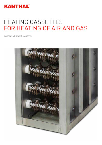
Chromalox Cable dSeriesLong LineHazardous ratings availableYesYesYesYesUsable on plastic pipeYes*NoNoNoCan be cut to length in fieldYesYesNoYesCan be single overlappedYesNoNoNo* SRL only on plastic pipe.Resistance WireOvercoat OverBraid (Optional)BinderBuss WiresBuss WiresTinned CopperBraid (Optional)JacketModule PointPrimary InsulationConductive MatrixTinned Copper Braid (Optional)Overcoat Over Braid (Optional)Self-RegulatingConstant WattageHigh TemperatureFluoropolymerOverjacketAlloy 825 SheathDenselyCompactedMineral Insulation16, 14, 12,10 AWGCopper Buss WiresMetallic BraidHigh TemperatureFluoropolymer JacketHigh TemperatureFluoropolymer Core MatrixTwin (Shown) or SingleResistance WiresSLL Long LineMineral InsulatedInstallationA. IMPORTANT — GENERAL NOTES REGARDINGINSTALLATION OF HEAT TRACING SYSTEMS.cluding 6 in. size. Includes use on elbows, tees, flanges,hangers and valves as shown. (show figures of heatingcable installed to various equipment as mentioned above).UL listed fiberglass insulation with a minimum k-factor of0.25 BTU/hr - F/ft2 -in with weatherproof cladding must beused.b. For systems having piping which connects between buildings in unheated areas, coolers and freezers.c. For systems having sprinkler piping that is installed in coolers or freezers where the temperature is -40 F or greater.Not intended to be used as the means to prevent freezing ofsprinkler branch lines including all accessories for these linesand automatic (deluge, preaction, dry pipe, alarm, etc.) valvesas referenced in NFPA 13.For use in Ordinary Hazard Occupancies only as specified inNFPA 13 the standard for the installation of sprinkler systems.Fire suppression system heater circuits must be connectedto monitoring equipment. A listed power supply relay with theFIRE HAZARD. Failure to follow these guidelines couldresult in property damage or personal injury.1. Read this instruction sheet and those enclosed with the accessories to familiarize yourself with the products.2. Selection of heating cable type and rating should be in accordance with the procedures located in the “Chromalox DesignGuide for Heat Tracing Products”.3. Ensure all pipes, tanks etc. have been hydrostatically testedprior to the installation of the heating cable.4. Always install tracing at the 5 or 7 o’clock position on a pipe.5. Installation Guidelines for fire protection systems:a. For use on insulated UL listed steel schedules 5, 10, 20and 40 standpipe and sprinkler system pipe up to and in3
—appropriate voltage coil shall be connected in parallel priorto the heat tracing (should show figure with typical installation). The output contacts of the listed power supervisory relayshould be connected to a listed fire control panel which hasprovisions for supervisory circuits.6. Do not attempt to heat trace any piece of equipmentwhich will not be insulated.7. Do not install heating cable on equipment whichcould become hotter than the heating cable’s maximum exposure temperature.8. Do not install heating cable in an area or on equipment which contains potentially corrosive materialswithout having a suitable protective jacket on thecable.9. The minimum bending radius for all Chromaloxheating cables is six times the minor diameter.10. Allow a minimum of 2” between cable runs.11. Always install heat tracing on the outside radius ofelbows.12. Never install heat tracing over expansion jointswithout leaving slack in the cable.13. Never use tie-wire or pipe straps to secure SelfRegulating Maximum Circuit length or ConstantWattage heating cables.14. Observe all published specifications. Do not exposecables to temperatures above their specified maximums. Do not run cables longer than specified maximum circuit lengths. See table 3 for details.15. Pumps and small vessels should be heat traced and controlled with the piping on the inflow end. The cable on thepump or vessel should be physically separate to permit disconnection during maintenance or removal.16. Use aluminum foil tape to cover the heating cable wheneverthe cable is not in good contact with the pipe (i.e. at supports,valves, pumps, etc.) or whenever its use is specified by the“Chromalox Design Guide for Heat Tracing Products”.17. Separately controlled circuits should be provided on dead endlegs and closed bypasses.18. No heat tracing circuit should extend more than two feet beyond a point where two or more pipes join when such junctions permit optional flow paths. In such cases, separatelycontrolled traces should be used.19. The minimum installation temperature for all Chromalox heating cables is -76 F (-60 C).20. Chromalox Type SRL heating cables are well suited for heattracing plastic pipes. Consult “Chromalox Design Guide forHeat Tracing Products” for design recommendations. Installation details AD1 through AD17 apply for plastic pipe only whenType SRL heating cable is used. Consult factory for applications involving other products.Allowing the cable to be walked on or subjeced to other abuse which could cause mechanical damage.3. When you reach the end of the circuit, secure the heater cableto the pipe using glass tape or plastic cable tie with a temperature rating compatible with the heater cable.If this end is to have an end seal installed, remember to leaveabout a foot of extra cable. If it is a power connection, leaveabout two feet of extra heater cable.4. (If the heater cable is to be spiralled, go to step 4A.)Begin attaching the cable to the pipe about every foot (.3 meters).Place the cable on the bottom half of the pipe at the 5 or 7o’clock position. Refer to installation detail AD1. Go to step 5.a. Note the path of the heater cable and the spiral factor ofthe design. A simple way to think about spiral factor is:A1.1 spiral factor means install 11 feet of heating cable onevery 10 feet of pipe, etc. At about every 10 feet of pipe,pull the required amount of cable and let hang in a loop,and attach the cable to the pipe.b. Rotate the loops around the pipe until all the slack hasbeen taken up. Even out the spirals of the heater cable andsecure to the pipe as necessary to obtain good contact.The entire circuit can be installed with hanging loops withthe spiralling on the pipe being done when you trace theheat sinks. Refer to installation detail AD3.5. At a heat sink (pipe supports, valves, pumps, reducers, gauges, bucket strainers, etc.), attach the heater cable to the pipejust before the heat sink. Refer to the design specs to determine the amount of heater cable you need to install on theheat sink. Pull this amount of cable into a loop, attach theheater cable on the other side of the heat sink and continueattaching the cable down the pipe as before.6. When you reach the heater cable reel, you should have theheater cable attached all along the pipe, with the correctamount of heater cable pulled in loops at all heat sinks. Attachthe cable to the pipe, (leave an extra foot if at an end seal, twofeet if at a power connection) and cut the heater cable fromthe reel.7. Install the heater cable loops on the heat sinks. Refer to theproper installation detail (AD5-AD12) for a general idea of howto install the cable, but remember: It is important to get the proper amount of heater cable onthe heat sink, rather than exactly as the detail shows. Thedetail is just a guide. Self-Regulating heater cables are very flexible and can besingle overlapped for installation ease. Feel free to use thisfeature when you can.FIRE HAZARD. Do not overlap constant wattage or mineral insulated heating cables.B. INSTALLING A SINGLE RUN OF CABLE ON A PIPE.1. Mount the reel of cable on a holder and place near one end ofthe pipe run to be traced. Choose the end from which it will bethe easiest to pay out the cable.2. Pay out the cable from the reel and loosely string along thepiping, making sure the cable is always next to the pipe whencrossing obstacles. For example, if the heater is on the wrongside of a crossing pipe, you will have to restring the cable orcut and splice it. By having the cable installed this way, it can be removedeasily from the heat sink without cutting if access to, orremoval of the heat sink is required.Note: If a tee is designed into the system, or if you are using twoor more short cable lengths to complete a circuit, allow two orthree feet of each cable to overlap. This will allow flexibility in assembling the connection kit and locating it on the pipe.C. INSTALLING MORE THAN ONE HEATING CABLE ON APIPE.There are two cases where you will need to install more than oneheater cable on a pipe: When the design calls for more than one cable. When the lines being heat traced are considered importantenough to install a backup (redundant) heat tracing system.To prevent damage to cable, avoid such things as:— Pulling the cable over sharp edges.— Forcibly pulling the cable free if it snags whilebeing paid out.4
The installation requirements are different for these cases.1. Installing multiple heater cables for design requirements.The most common multiple cable requirement is two cableson a pipe. Below are the recommended techniques for the twocable systems. They also apply to installations where three ormore cables are to be installed on a pipe.There are two ways of paying out two heater cables along apipe. The first is to locate two reels of heater cable and supplyone cable from each. This method works for all types of pipingruns.However, it may increase material waste by leaving unusablelengths from two reels. The second way is to supply both cables from one reel. This method is generally the easiest forrelatively straight, simple piping runs. For each circuit, decidewhich method to use and then go to the appropriate part below.a. Supplying cable from two reels.The general procedure here is the same as given earlier,but there are a few things to do to make sure the system iscorrectly done.i. At each heat sink, the easiest thing to do is supply theextra heater called for by the design drawing from onlyone heater cable. This avoids having to measure out halfof the requirement from each cable.ii. When doing the previous step, leave a small loop other cable at equipment which may be serviced, such aspumps, valves, instruments, etc. This is so both heatercables may be removed enough for future access.b. Supply heater cables from one reel.The general procedure is the same as given earlier, butthere are a few things to do to make sure the system iscorrectly done.i. With this method, a loop is pulled for the entire circuit.To do this, attach the end of the heater cable to the pipenear the heater cable reel. Remember to leave enoughextra cable for the type of connection to be installed.ii. Begin pulling the cable off the reel in a large loop downthe piping run. Be sure to keep the cable next to thepipe. Moving down the run, continue attaching the cable to the pipe, leaving the side of the loop going backto the reel unattached.iii. You will want both sides of the loop to be about thesame length to avoid future problems. Also, it is easierto install the extra cable required at each heat sink fromonly one cable. Therefore, pull the right amount of extraheater cable needed at every second heat sink from theside of the loop you are attaching to the pipe. At theremaining serviceable heat sinks (pumps, valves, instruments, etc.) don’t forget to leave a short loop of cablefor slack when access to the equipment is needed.iv. When the end of the piping run is reached, pull theproper amount of extra cable for the connection to beinstalled.v. Now, begin working the remaining side of the loop backtoward the reel, installing it on the pipe and heat sinksas required.2. Installation for Backup (Redundant) Systems.The purpose of a backup system is to provide the properamount of heat from the second heater cable if there are problems with the first. Therefore, each cable must be installed soit can do the job alone. The simplest way to do this is to installthe first heater cable as given in Section B. Then, go back andinstall the backup heater cable the same way.There are several things to keep in mind: The power connections and end seals for the two cablesare often designed to be at opposite ends of the run in aredundant system. Remember to leave the proper amountof extra cable for the connection to be installed on eachcable at that end. On piping one inch IPS or smaller, it can be difficult to apply both heater cables with good contact at all places. Themain thing is to get the correct amount of cable installed.However, try to get as much contact with the piping andheat sinks from both cables as possible.Supplementary Instructions for ATEX and IECEx ApplicationsSRL and SRM/E Self-Regulating Heating Cables, U SeriesConnection Accessories Type UPC, UMC, UES and RTES1. Do not bend the cable for a length of 300mm from the cablegland inlet.2. Connection and termination of Chromalolx ATEX and IECExcertified cable must be carried out by using the U Series ofcertified cable connection kits as supplied by Chromalox, Inc.These are only to be used for the operations for which theywere designed.3. The supply circuit to the heating cables must be protected bya safety differential device or equivalent ground fault protection.4. The earthing braid of the heat trace cable must be bonded toa suitable earth terminal.5. The minimum cable installation temperature for SRL andSRM/E cable is -40 C (-40 F).6. The certified minimum cable exposure temperature for SRLand SRM/E cable is -60 C (-76 F).ELECTRIC SHOCK HAZARD. Disconnect all power before installing or servicing heating cable. Failure to doso could result in personal injury or property damage.Heaters must be installed by a qualified person in accordance with IEC 62086-2 2001.Any installation involving electric heating cables mustbe performed by a qualified person and must be effectively grounded in accordance with IEC 62086-2:2001to eliminate shock hazard.5
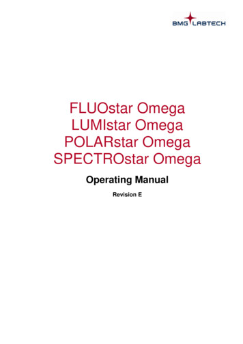
Typical Installation DetailAD1 - One Run of CableAD1 - Two Runs of CableAD3 - One Cable-Spiralling MethodAD4 - One Run of Cable at Pipe ElbowAD5 - Orifice FlangeAD6 - Expansion Joint6
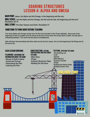
AD7 - Welded SupportAD8 - Shoe SupportAD9 - ValveAD10 - Pressure GaugeAD11 - Diaphragm Pressure GaugeAD12 - Level Gauge7
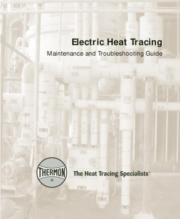
AD13 - U Series Power ConnectionAD14 - U Series Splice & Tee ConnectionAD14 - EL Series Splice and Tee KitAD15 - End SealAD15-2AD16 - DL Series Power Connection8
AD17 - DL Series Splice & Tee ConnectionAD18 - Sensor PlacementWiring7. All equipment must be properly grounded.8. Install installation accessories according to the instructionsincluded in the kits and per installation details AD13 throughAD17.ELECTRIC SHOCK HAZARD. Disconnect all power before installing or servicing heating cable. Failure to doso could result in personal injury or property damage.Heater must be installed by a qualified person in accordance with the National Electrical Code, NFPA 70.To prevent equipment damage, Circuits fed from overhead lines should be protected by secondary lighting arrestors.ELECTRIC SHOCK HAZARD. Any installation involvingelectric heating cables must be performed by a qualifiedperson and must be effectively grounded in accordancewith the National Electrical Code to eliminate shockhazard.CONTROLS:1. All heating circuits should have temperature controls. Temperature control of the pipeline can be obtained through variousChromalox temperature controls.2. Contactors must be used when load currents exceed the rating of the thermostat contacts. Equipment protection groundfault (30 mA EPD) thermal breakers are recommended withtype SRL, SRM/E, SRP & SLL.3. The temperature control should be mounted in a locationwhere it will not be subjected to excessive shock or vibration.4. Line sensing temperature sensors should be mounted in accordance with Installation Detail AD18 (see Detail above).5. Ambient sensing temperature sensors should be located at apoint where the lowest ambient temperature is expected.ACCESSORIES:1. Selection of installation accessories should be in accordancewith ChromaTrace 3.0 design software program. Ensure accessories are rated for the area where they are located. IfChromalox accessories are not used with cable, all third partyapprovals are voided.2. Only use Chromalox installation kits and use them only for theoperations for which they are designed.3. The instructions included in the Chromalox installation accessories must be followed in order for the third party approvals(UL, FM, CSA, ATEX, IECEx, etc.) to apply.4. Junction boxes must be in accordance with the requirementsof the area classification.5. All outdoor junction boxes must be located above grade level.Covers should be kept on the boxes at all time when not beingworked in.6. All terminations must be protected from the weather and fromphysical damage by locating them either under the weatherproof insulation or inside an appropriate junction box.To prevent equipment damage, handle and secure temperature sensors, especially thermostat bulbs and capillaries with care to avoid distortion or crimping whichmight impair control accuracy.6. Exposed thermostat capillaries should have mechanical protection.9
End CapEnd CapHeat Generating MatrixL2Power SupplyBuss WireL1Buss WireHeat Resistance WireL2Power SupplyL1ThermostatThermostatContactorContactorHeat Resistance WireHeat Generating MatrixL2 PowerL1 SupplyL2 PowerL1 SupplyBuss WireEnd CapBuss WireEnd tII. Constant WattageI. Self-RegulatingContactorEnd CapHeat Resistance WireCold LeadHeat Resistance WireL2Power SupplyL1L2 PowerL1 SupplyEnd tatIII. Mineral InsulatedInstallation Testing3. Inspect the insulation resistance of the circuit using a 500 Vdc.It is strongly recommended that higher test voltages be used.Mineral Insulated (MI) cables should be tested at, but not exceed 1,000 Vdc, and polymeric cables (SR, CWM, SLL) shouldbe tested at 2,500 Vdc. megger. Always perform this test atthe power connection. See the following table for minimuminsulation resistance readings. Any cable with an insulationresistance below the recommended value should be removedand factory should be contacted.4. Check voltage at end of circuit and record in log.(See page 14).When the heater cable and connections for a circuit have beencompleted, immediately perform the following checks.1. Visually inspect the heater cable and temperature controls forsigns of mechanical damage. If damage is seen, either replacethe complete heater cable, or cut out the damaged sectionand replace using the proper splice connection for the areaand cable you are using.2. Inspect all connections to be sure they are correctly assembled. Be sure each heater cable entry to a connection has agrommet and the compression plates and caps are properlytightened.Chromalox SRDelivery20 MΩInstallationPre-Insulation20 MΩInstallationPost-Insulation5 MΩMaintenance5 MΩChromalox MI20 MΩ20 MΩ5 MΩ5 MΩChromalox Snow Melt20 MΩ20 MΩ5 MΩ5 MΩ10
Thermal InstallationAn installed heating circuit should be thermally insulated immediately to provide protection from damage from ongoingwork. Things to remember about insulating:1. Insulate the equipment being heat traced as soon as possibleafter the heating cable is installed. This will protect the cablefrom possible physical damage.2. The type and thickness of thermal insulation specified on thedesign drawing must be used. If you use another type or thickness, the heater cable type or amount may have to be changed.3. Never install wet insulation. Both the piping and the insulationmust be dry when thermally insulating a circuit. Wet insulationmay cause start-up or operational problems.4. Properly weatherproof the thermal insulation. All places wherevalve stems, conduits, pipe supports, connection housing, thermal capillary tubes, etc. extend outside the insulation jacketingmust be sealed with a suitable compound to keep water out.5. Insulate valves fully up to, and including, the packing gland.6. Heat trace and fully insulate the face of all non-diaphragm pressure instruments.7. Insulation must be covered by a weatherproof barrier, such asan aluminum jacket.8. If you are using metal jacketing and sheet metal screws, be surethe screws are not long enough to penetrate the thermal insulation and damage the heater cable.9. Again, perform the megger test on the circuit immediately afterthe thermal insulation is installed to detect if any mechanicaldamage may have occurred.10. When the insulation and the weatherproofing is complete, attach “Electric Traced” labels on the outside of the insulation.These should be installed where they are visible from normaloperations, usually on alternating sides about every 10 feet. It isalso useful to mark the location of any connections buried underthe insulation.Additional requirements for rigid thermal insulations:1. In the standard single heater cable installation, rigid insulationsdo not need to be oversized. However, they should be carved sothere is no gap in the insulation.2. In case of redundant or multiple heater cables, rigid insulationswhich are .500 inches oversized should be used.Commission TestingFor systems controlled by line-sensing thermostats:1. Set the thermostat to the desired control temperature.2. Turn the main circuit breaker ON.3. Turn ON the branch circuit breakers controlled by the thermostat.4. Allow the pipe temperatures to be raised to the control point.This may take up to four hours for most circuits (large fullpipes may take longer).5. Measure the amperage draw, ambient temperature, and pipetemperature for each circuit and record in the installation log.This information may be needed for future maintenance andtroubleshooting.1. Again, visually inspect the piping, insulation and connections forthe heater cable to make sure no physical damage has occurred ifsome time period has elapsed since the installation and start-up.2. Megger the system again to determine if damage not readilyvisible has occurred.3. Turn all branch circuit breakers to the OFF position.For systems controlled by ambient-sensing thermostats:1. If the actual ambient temperature is higher than the desiredthermostat setting, turn the thermostat setting up high enoughto turn the system ON or (some models) turn the selectorswitch to the ON position.2. Turn the main circuit breaker ON.3. Turn the branch breakers ON one-by-one until all are on.4. Allow system to run at least four hours in order to let all pipesreach steady-state.5. Measure the amperage draw, ambient temperature and pipetemperature for each circuit and record in the installation log.This information may be needed for future maintenance andtroubleshooting.6. When the system is completely checked out, reset the thermostat to the proper temperature.For redundant systems:Follow the procedure above for the type of control system youhave, but commission the systems one at a time. Start up the primary system, qualify it and shut it down. Then start up the backupsystem, qualify it and shut it down.SpecificationsTable 1 – Maximum TemperaturesMax. Maintain(Power On)Max. Exposure(Power Off)SRL / HSRL150 F185 FSRM/E / HSRM302 F420 FCable TypeCWMSee table belowSee table belowSRF150 F185 FSLL302 F450 FSRP230 F275 F11
Table 2 – CWM Cable Maximum Maintenance TemperaturesTemperatures ( F)Output (W/Ft.)3w/o AT-1 Tape4340w AT-1 931412222307200304296Table 3 – MaximumSRL / HSRL Circuit Breaker Selection (Max. Circuit Lengths in Ft.)SRLSRLSRLSRLSRLSRLSRLSRL50 F Start-Up (Ft.)CableRating/ HSRL3-1C/ HSRL3-2C/ HSRL5-1C/ HSRL5-2C/ HSRL8-1C/ HSRL8-2C/ HSRL10-1C/ 02154201602600 F Start-Up 0555180360145265105170-20 F Start-Up (Ft.)25A 30A 40A330 360 NR660 NR NR225 270 NR450 540 NR180 215 NR335 395 420130 155 180210 255 2020A2454951603251302359516025A 30A 40A300 360 NR600 660 NR205 245 270405 490 540165 200 210300 350 420120 140 180195 240 320SRP Circuit Breaker Selection (Max. Circuit Lengths in Ft.)CableRatingSRP 5/1SRP 10/1SRP 15/1SRP 5/2SRP 10/2SRP 15/215A1451007529520015050 F Start-Up 27040053019529539050A4903302507506655000 F Start-Up (Ft.)20A30A 3532015A110706022014512050A360240200720480400-20 F Start-Up (Ft.)20A30A 029015A70655513513011050A225215180450440360SRM/E / HSRM Circuit Breaker Selection (Max. Circuit Lengths in RM/ESRM/ESRM/ECableRating/ HSRM 3-1/ HSRM 3-2/ HSRM 5-1/ HSRM 5-2/ HSRM 8-1/ HSRM 8-2/ HSRM 10-1/ HSRM 10-2/ HSRM 15-1/ HSRM 15-2/ HSRM 20-1/ HSRM 20-250 F Start-Up 3050 F Start-Up ANRNR375750325650250490165360140270-20 F Start-Up 50490210420160335SRF Circuit Breaker Selection (Max. Circuit Lengths in Ft.)CWM SpecificationsCircuit Load(Amps / Ft.)0.033Max CircuitLength (Ft.)350CWM 8-1CT0.067CWM 12-1CT40 F Start-Up (Ft.)0 F Start-Up (Ft.)240CableRatingSRF 3-1C20A35030A36040ANR20A27030A36040ANR0.100200SRF 3-2C660NRNR555660NRCWM 4-2CTCWM 8-2CT0.0170.033700480SRF 5-1C230270NR180270NRCWM 12-2CT0.050400SRF 5-2CSRF 8-1C450180540215NRNR360145540215NRNRCWM 12-4CT0.025780SRF 8-2C330420420265395420ModelCWM 4-1CT12
SLL Specifications16.00Nominal Output Ratings on Metal Pipe - 120 VACNominal Output Ratings on Metal Pipe - 240 1500Cable Length (ft.)16.0014.0014.00W/Ft.12.00W/Ft.12.00Nominal Output Ratings on Metal Pipe - 480 6.00SLL106.002500Nominal Output Ratings on Metal Pipe - 600 VACSLL458.002000Cable Length 008000Cable Length (ft.)Cable Length (ft.)NR Not Required. Maximum circuit length has been reached in a smaller breaker size.Note — Thermal magnetic circuit breakers are recommended since magnetic circuit breakers could “nuisance trip” at low temperature.MaintenanceRepair or replace all damaged heater cable, connections, thermalinsulation and weatherproofing using only Chromalox connections and methods before testing the system.Record all repairs made and measurements taken in the installation and maintenance log.Recommended maintenance for Chromalox heat tracing systemsconsists
The minimum installation temperature for all Chromalox heat-ing cables is -76 F (-60 C). 20. Chromalox Type SRL heating cables are well suited for heat tracing plastic pipes. Consult "Chromalox Design Guide for Heat Tracing Products" for design recommendations. Installa-tion details AD1 through AD17 apply for plastic pipe only when