Transcription
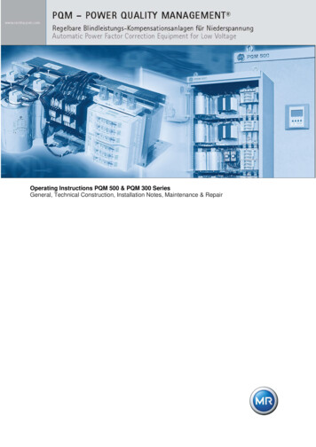
Operating Instructions PQM 500 & PQM 300 SeriesGeneral, Technical Construction, Installation Notes, Maintenance & Repair
Power Quality ManagementOperating InstructionsPQM500 & PQM300 SeriesPage 1 of 12Contents1General21.1Using the manual . 21.2Safety notes . 21.3Important notes on using the system . 41.4Standards and responsibilities . 42General data of the system52.1Technical data - nameplate . 52.2Ambient conditions. 52.1Intended use . 63Installation and Commissioning63.1Operation . 73.2Operational switching off . 73.3Protective trip (in the event of a fault) . 83.4Operational switching on . 83.4.1 Reconnection after operational shutdown . 83.4.2 Reconnection after maintenance and repair measures . 84Maintenance94.1Preparation . 94.2Measures to be carried out. 94.2.14.2.24.2.34.2.45Inspection schedule . 10Replacement of components . 11Cleaning. 11Greasing. 11Dismantling & Waste Disposal125.1Lifespan. 125.2Dismantling . 125.3Waste Disposal . 12Version 1.5Version 1.4Version 1.3Version 1.2Version 1.1Coverpage changedContent correctionsFormatting changedAddition to MaintenanceAddition to Waste Disposal Maschinenfabrik Reinhausen GmbH 2012.Manual PQM500 PQM300 Rev05 en.docx
Power Quality ManagementOperating InstructionsPQM500 & PQM300 Series1Page 2 of 12General1.1 Using the manualThese Operating Instructions contain general as well as system-specific information.Technical details on design and open/closed-loop control (if present) can be taken from the relevantsections of the technical documentation.If there is a lack of information or there are further questions, we can be contacted at the addressbelow:Maschinenfabrik Reinhausen GmbHWiebestrasse 4610553 BerlinTel. 49 30330915-0Fax: 49 30330915-25E-mail: support.pqm@reinhausen.com1.2 Safety notesWhen operating electrical switchgear and control gear, it is inevitable thatcertain parts of these systems will be carrying dangerous electrical voltageand mechanical parts, even when remotely controlled, can move very quickly.Serious physical injuries and material damage may occur if the safetyregulations and warning signs are not observed.Only appropriately qualified staff should work on or in the vicinity of thiscompensation system.These members of staff must be thoroughly familiar with all warnings inaccordance with these Operating Instructions.Trouble-free and safe operation of this compensation system assumes propertransport, professional storage, positioning and installation in addition tocareful operation and maintenance. Maschinenfabrik Reinhausen GmbH 2012.Manual PQM500 PQM300 Rev05 en.docx
Power Quality ManagementOperating InstructionsPQM500 & PQM300 SeriesPage 3 of 12DANGERas defined by these Operating Instructions and by the warning signs on theproducts themselves means that death, severe physical injury or substantialmaterial damage will occur if the appropriate precautions are not taken.Warningas defined by these Operating Instructions and by the warning signs on theproducts themselves means that death, severe physical injury or substantialmaterial damage will occur if the appropriate precautions are not taken.Cautionas defined by these Operating Instructions and by the warning signs on theproducts themselves means that slight physical injury or material damagemay occur if the appropriate precautions are not taken.Qualified staffas defined by these Operating Instructions and by the warning signs on theproduct itself are people who are familiar with positioning, installation,commissioning and operation of the product and who have the relevantqualifications for their job, such asI.II.III.training and instruction or authorization to switch circuits andequipment/systems on and off, to ground them and to identificationmark them in accordance with safety engineering standards.Training or instruction in accordance with safety engineeringstandards on the care and use of appropriate safety equipment.Training in first aid. Maschinenfabrik Reinhausen GmbH 2012.Manual PQM500 PQM300 Rev05 en.docx
Power Quality ManagementOperating InstructionsPQM500 & PQM300 SeriesPage 4 of 12The 5 safety rulesPrior to starting work:1.Isolate with a safety disconnection function2.Secure against reconnection3.Ensure safe isolation from supply (*)4.Ground and short-circuit5.Cover/fence off adjacent live partsDANGER(*) After isolating the system, the capacitors of the capacitive steps still havea residual voltage (direct current). Exercise caution regarding the capacitors’discharge time.1.3 Important notes on using the system Trouble-free and safe use of the compensation system assumes:o Proper transporto Professional installation and commissioningo Careful operation and maintenance by qualified staffo Observance of these Operating Instructionso Compliance with the positioning, operating and safety regulations applicable at theinstallation site1.4 Standards and responsibilities DIN VDE 0113DIN VDE 0100All applicable accident prevention regulations of the employer's liability insurance associationAdditional country and company-specific requirements may be applied as necessary. Maschinenfabrik Reinhausen GmbH 2012.Manual PQM500 PQM300 Rev05 en.docx
Power Quality ManagementOperating InstructionsPQM500 & PQM300 Series2Page 5 of 12General data of the system2.1 Technical data - nameplate You will find the technical data of your system on your system’s nameplate which is located onthe inside of the door. Every assembly module also has its own nameplate on the front. Pleasecheck before connecting to the low voltage network that the mains data shown on thenameplate, such as nominal voltage, nominal frequency and network configuration, match theconditions on site.2.2 Ambient conditions The permitted ambient conditions depend on the system’s degree of protection. You will find thison the nameplate. The standard degree of protection is IP20.The following table provides information about the significance of the IP code:Protection against solid bodies1stDescriptionnumeral0no protection1Solid bodies 50 mm2Solid bodies 12.5 mm3Solid bodies 2.5 mm4Solid bodies 1 mm Protection against water2ndDescriptionnumeral0no protection1Dripping water falling vertically2Dripping water falling at an angle of 15 3Spray water falling at an angle of 60 4All-round protection against spraywaterClimatic conditions:Relative humidity: max 95%, non-condensingDo not use the systems in corrosive environments; environments containing chlorine, sulphur, acidor salt may damage the system.PQM 500:maximum ambient temperature: 40 CWe recommend an ambient temperature of 25 C for an extended lifetime of the capacitors.PQM 300:maximum ambient temperature: 40 CWe recommend an ambient temperature of 25 C for an extended lifetime of the capacitors. Maschinenfabrik Reinhausen GmbH 2012.Manual PQM500 PQM300 Rev05 en.docx
Power Quality ManagementOperating InstructionsPQM500 & PQM300 SeriesPage 6 of 122.1 Intended use 3Compensation systems of type PQM 300 & PQM 500 are used for the incoming supply ofcapacitive reactive power. The power discharged can either be controlled by a reactive powercontroller or can be set to a fixed value.Subsequent technical modifications to the systems, in particular the use of capacitors, fuses orcontactors with different technical parameters or third-party components, without consulting MRis prohibited for reasons of safety.It is also prohibited to carry out modifications to protective covers, safety equipment and safetysettings without consulting MR.Installation and Commissioning Remove the packaging and transport materials at the installation site. Check the system fortransport damage prior to installation.Set up the system on a firm foundation in a stable position; its weight is shown in the circuitmanual. Caution, the system may be top-heavy when being transported on the pallet truck. Takecare during installation that none of the system’s ventilation openings are covered up, the rear airinlet vent of the PQM 300 in particular must remain open (maintain distance from wall, seecircuit manual). Connect the system to the grid. Dimension your leads according to the rated current of the fuseprotection, the type of lead and the type of installation, if necessary allowing for additionalderating factors depending on local conditions. Select the compensation system’s fuse protectionaccording to EN DIN IEC 60269-5. Test the connection according to the applicable standards. Connect the control wires according to the circuit manual. Pay attention to the polarity of thecurrent transformer and open all existing short-circuiting jumpers after installation. Themeasurement must be situated upstream of the connection point between system and grid in thedirection of the incoming supply. Energize the system and then parameterize the controller. There are dedicated operatinginstructions for operating the controller. First of all, use the controller’s automated initialization;in this case, the controller adjusts automatically to the connections and compensation stepsprovided. Test the controller’s measurement because efficient control can only take place if measuring iscorrect:o The measured current must match the measuring instruments of its incoming supplyotherwise the current transformer’s ratio must be adjusted in the controllero The voltage should correspond to the rated voltageo If the current and voltage measurement are correct but the power or the power factor isnot feasible, correct the phase difference between current and voltage measurement inthe controller’s settings. Test the controller’s setting:o The target power factor should be set to 0.98io Test the alarm output to the outside and remote control from outside if presento Your system is now ready for operation; the controller should now switch the steps onand off according to the reactive power demand when load changes occur.o The roof fans, if present, should switch on in a controlled manner Maschinenfabrik Reinhausen GmbH 2012.Manual PQM500 PQM300 Rev05 en.docx
Power Quality ManagementOperating InstructionsPQM500 & PQM300 SeriesPage 7 of 123.1 Operation3.2 Operational switching off Operational switching off of the compensation steps is carried out by the system-internalswitchgear, e.g. capacitor contactor. The corresponding upstream circuit breaker or fuse circuit is used to isolate the system or if thereis no internal switchgear present. Notes: With compensation systems connected parallel to equipment without internal switchgear,switching off of the upstream circuit breaker leads to shutdown of the drive!WarningFor capacitive compensation steps, it is imperative to adhere to the dischargetime of 3 min specified by the manufacturer.The system’s busbar is energized in the switched off state.DangerThe contactor-switched capacitor steps are loaded with a dangerous residualvoltage during the discharge time!In thyristor systems, the capacitors are charged to the grid’s peak voltageeven when the thyristors are switched off!Warning/noteIt is imperative to observe the 5 safety rules prior to working on the system(see Section 1.2) Maschinenfabrik Reinhausen GmbH 2012.Manual PQM500 PQM300 Rev05 en.docx
Power Quality ManagementOperating InstructionsPQM500 & PQM300 SeriesPage 8 of 123.3 Protective trip (in the event of a fault) After a protective trip of individual steps or the whole system by the controller, the system mustnot be reconnected unless the following points are observed!oA systematic fault analysis is necessary prior to connection Check the thermal conditions (cooling vents, roof panels, fans) Check the set values in the controller Check the capacitors Check the overcurrent protection equipmentoReplace any defective components
2.1. Intended use . 6 3 Installation and Commissioning . Compensation systems of type PQM 300 & PQM 500 are used for the incoming supply of capacitive reactive power. The power discharged can either be controlled by a reactive power controller or can be set to a fixed value. Subsequent technical modifications to the systems, in particular the use of capacitors, fuses or contactors .