Transcription
Index of Sub AssembliesIllustration of Sub AssembliesIndex of Sub AssembliesIllustration of Sub AssembliesIllustration of Sub AssembliesIndex of Sub AssembliesIllustration of Sub AssembliesIndex of Sub AssembliesP-494RETURN TO MAIN INDEXPARTS LIST FORRANGER 305D (CE)RANGER 305D (CE)P-494
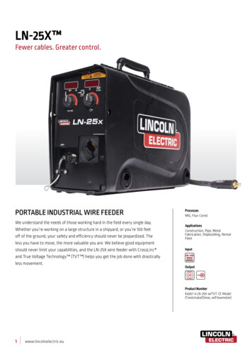
P-494-AILLUSTRATION OF SUB-ASSEMBLIES7Index of Sub AssembliesIndex of Sub AssembliesP-494-A63Index of Sub Assemblies4512Index of Sub AssembliesHIGIDLEHAUTOIDLEDRANGER 305D (CE)08-06-2009
RANGER 305D (CE)For Codes: 11122, 11123, 11189, 11190, 11314,11315, 11458, 11459 & 11587Do Not use this Parts List for a machine if its code number is not listed. Contact the Service Department for anycode numbers not listed.PAGE NO.CODE NO.234567Stator Rotor AssemblyBlower Baffle AssemblyBase, Fuel Tank, BatteryAssemblyEngine AssemblyCovers & Case Back AssemblyOptional EquipmentIllustration of Sub AssembliesIllustration of Sub AssembliesSUB ASSEMBLYPAGE NAME1Control Panel AssemblyUse the Illustration of Sub-Assemblies page and the table below to determine which sub assembly page andcolumn the desired part is located on for your particular code machine.Sub Assembly ItemNo.Illustration of Sub AssembliesP-494-A.1Case Front AssemblyIllustration of Sub AssembliesRETURN TO MAIN INDEXP-494-A.1P-494-B.1 P-494-C P-494-D P-494-E P-494-F P-494-G P-494-H P-494-J11122 (CE UK)111111111123 (CE Euro)221111211189 (CE UK)111112311190 (CE Euro)221112411314 (CE UK)131123511315 (CE Euro)241123611458 (CE UK)331224711459 (CE Euro)441224811587 (CE)5512249RANGER 305D (CE)08-06-2009
OPTIONAL EQUIPMENT LISTINGP-494-B.1Miscellaneous Options Available for your machine are listed below:# Indicates a change this printing.DESCRIPTION . . . . . . . . . . . . . . . . . . . . . . . . . . . . . . . . . . . . . . . . . . . . . . . . . . . . . . . . . . . . . . . . . . . . . . .PART NUMBERAccessory Package . . . . . . . . . . . . . . . . . . . . . . . . . . . . . . . . . . . . . . . . . . . . . . . . . . .Order K704Spark Arrestor (Not required for codes above 11190) . . . . . . . . . . . . . . . . . . . . . . . .Order K1898-1Remote Output Control (7.6m) . . . . . . . . . . . . . . . . . . . . . . . . . . . . . . . . . . . . . . . . . .Order K857Remote Output Control (30.5m) . . . . . . . . . . . . . . . . . . . . . . . . . . . . . . . . . . . . . . . . .Order K857-1Index of Sub AssembliesIndex of Sub AssembliesIndex of Sub AssembliesIndex of Sub AssembliesP-494-B.1RANGER 305D (CE)08-06-2009
Index of Sub AssembliesIndex of Sub AssembliesIndex of Sub AssembliesIndex of Sub AssembliesNOTESRANGER 305D (CE)
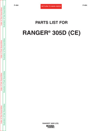
Part NumbersIndex of Sub AssembliesPart NumbersIndex of Sub AssembliesPart NumbersIndex of Sub AssembliesPart NumbersIndex of Sub AssembliesP-494-CP-494-CCase Front GER 305D (CE)9122904-13-2010
Sub Assembly IllustrationSub Assembly IllustrationSub Assembly IllustrationSub Assembly IllustrationIndex of Sub AssembliesIndex of Sub AssembliesIndex of Sub AssembliesIndex of Sub AssembliesP-494-C.1# Indicates a change this printing.P-494-C.1Use only the parts marked “x” in the column under theheading number called for in the model index page.ITEM DESCRIPTIONPART NO.QTY.1 2 3 4 5 6 7 8 XXXXX XXXXXXXXXXXXXXX X XXXXXXXXX XXXXCase FrontOutput Terminal Kit3 Phase Circuit BreakerMounting BracketMounting Plate (Not Shown)Thread Forming Screw (Not Shown)Lock Washer (Not Shown)#10-24 HN (Not Shown)Circuit Breaker BootResidual Current Device (RCD)Receptacle, 400V (Eur)Receptacle, 230V (Eur)Receptacle, 230V (Eur)Receptacle, 115V (UK)#10-24 HLN1/4-20 HNThread Forming ScrewConnector CapConnector CapShunt & Lead Assembly1/2-13 x .875 HHCS (Not Shown)Plain Washer (Not Shown)Lock Washer (Not Shown)RF-Bypass Filter AssemblyFlat Washer (Not Shown)Lock Washer#10-24 HNHarness Assembly (Not Shown)Harness Assembly (Not Shown)Connector & Lead Assembly, Includes:Connector & Lead Assembly, Includes:ConnectorConnectorGround Screw Assembly Ref.Thread Forming ScrewPlain Washer (Not Shown)#10-24 HN (Not Shown)Lock Washer (Not Shown)Lock Washer (Not Shown)Rating PlateRating PlateRating PlateThread Forming Screw (Cutting)Output Stud CoverOutput Stud Cover PlateThread Forming ScrewNSS - Not Sold SeparatelyRANGER 305D (CE)XXXXXXXXXXX X XXXXXXXXXXXXXX X XXXXXXXX X XXXXXXXXXXXXXXXX XXXXXXXXXXXXXX X XXXXXXXXXX XXXXXXXXXXXXXXX X XXXXXXXXXXXXX X XXXXXXXXX X XXXXXXXXXXXXXXXX XXXXXXXXXXXXXX X XXXXXXXXX XXXXX04-13-2010
Index of Sub AssembliesPart NumbersIndex of Sub AssembliesPart NumbersPart NumbersIndex of Sub AssembliesPart NumbersIndex of Sub AssembliesP-494-D20A25P-494-DControl Panel Assembly562672414CRANGER 305D (CE)1735A2A2314A1614B 14A154A3318121527183A1922A2104-13-2010
Sub Assembly IllustrationSub Assembly IllustrationSub Assembly IllustrationSub Assembly IllustrationIndex of Sub AssembliesIndex of Sub AssembliesIndex of Sub AssembliesIndex of Sub AssembliesP-494-D.1# Indicates a change this printing.P-494-D.1Use only the parts marked “x” in the column under theheading number called for in the model index page.ITEM DESCRIPTIONPART NO.QTY.1 2 3 4 5 6 7 8 XXXXXXXXXXXXXXXX X X XX XXXXXXXX XX XXXXXXXXXXXTop BezelSelf Tapping Screw (Not Shown)Right BezelSelf Tapping Screw (Not Shown)Left BezelSelf Tapping Screw (Not Shown)Switch, Push-ButtonStart ButtonHour Meter-MiniatureKnob“O” Ring (Not Shown)Connector & Lead Assembly, Includes:Potentiometer (10K)Potentiometer SpacerRotary Switch (Not Shown)Switch, Toggle, SPSTSealing Boot (Not Shown)Nameplate, 305D- 50Hz/UK (G4578-1) (Part of G4578)Nameplate, 305D- 50Hz/Europe (G4579-1) (Part of G4579)Nameplate, 305D- 50Hz (G6435-1) (Part of G6435)Switch, Toggle, DPDTSealing Boot (Not Shown)KnobFront Door NameplateFront Door NameplateDoor Welded AssemblyRivet (Not Shown)LatchCatch BracketSelf Tapping Screw (Not Shown)Pilot LightFastener ButtonEngine Service Decal (L12037-3) (Part of L12037)Engine Service Decal (L12922-3) (Part of L12922)Electric Fuel GaugeToggle SwitchSealing Boot (Not Shown)Plug & Lead Assembly (Not Shown)Circuit BreakerSealing BootDigital Weld Meter Kit, Includes: (35A thru 35E)Meter Housing Asbly (L11160) (Includes Meter)Meter Housing Seal (Not Shown)Meter Bezel (Not Shown)Lens (Not Shown)#4-40 x .375 SS-PPNHS (Not Shown)#6-32 HNPlain WasherNSS - Not Sold SeparatelyRANGER 305D (CE)XXXXXXXXXXXXXXXX X X XX XXXXXXXX XX XXXXXXXXXXXXXXXXXXXXXXXXXXXXX XXXX XXXXXXX XXXXXXXXXXXXXXXXXXXXXXXXXXXXXXXX X XXXX XXXXXXX XXXXXXXXXXXXXXXXXXXXXXXXXXXXXXXX XXXX XXXXXXXX XXXXXXXXXXXXXXX04-13-2010
Part NumbersIndex of Sub AssembliesPart NumbersIndex of Sub AssembliesPart NumbersIndex of Sub AssembliesPart NumbersIndex of Sub AssembliesP-494-E7P-494-EStator Rotor Assembly164D1810981ARANGER 305D (CE)4F171114154G4E1254B4C4A131C1B62C2B2A08-06-2009
Sub Assembly IllustrationSub Assembly IllustrationSub Assembly IllustrationSub Assembly IllustrationIndex of Sub AssembliesIndex of Sub AssembliesIndex of Sub AssembliesIndex of Sub AssembliesP-494-E.1P-494-E.1# Indicates a change this printing.Use only the parts marked “x” in the column under theheading number called for in the model index page.ITEM DESCRIPTIONPART NO.QTY.1 2 3 4 5 6 7 8 XXXXXXXXXXXXXXXXXXXXXStator Frame Assembly3/8-16 x 1.25 HHCSLock WasherPlain WasherLock Washer3/8-16 HNDisc Clamping Bar5/16-18 x .875 HHCSLock WasherCoupling DiscRotor Clamping Ring5/16-24 x .875 HHCSLock WasherRotor & Shaft AssemblyTolerance RingBlowerPlain WasherBearingBrush & Brush Holder Assembly, Includes:Brush Holder CartridgeBrush AssemblyBrush Assembly Retainer11 Brush Holder Bracket12 Self Tapping Screw13 1/4-20 x 1.00 HHCS14 Lock Washer14A Flat Washer15 1/4-20 HN16 Firewall17 Bushing18 Door BumperRANGER 305D (CE)08-06-2009
Part NumbersIndex of Sub AssembliesP-494-FP-494-FBlower Baffle Assembly511H 11J 11K811B11A11HPart NumbersIndex of Sub Assemblies311G9A11F 11E 11D19B213A6B46C6D101618AIndex of Sub AssembliesPart NumbersIndex of Sub AssembliesPart Numbers18C12A12C7A13A14ARANGER 305D (CE)08-06-2009
Sub Assembly IllustrationSub Assembly IllustrationSub Assembly IllustrationSub Assembly IllustrationIndex of Sub AssembliesIndex of Sub AssembliesIndex of Sub AssembliesIndex of Sub AssembliesP-494-F.1P-494-F.1# Indicates a change this printing.Use only the parts marked “x” in the column under theheading number called for in the model index page.ITEM 15A15B15C15D15E161718A18B18C18DBlower Baffle Assembly, Includes:Blower Baffle Assembly, Includes:BaffleWarning DecalBaffleHeat Sink HolderThread Forming Screw (Cutting)Thread Forming Screw (Cutting) (Not Shown)Plain WasherLock Washer1/4-20 HNWeld Control PC Board AssemblyWeld Control PC Board AssemblySelf Tapping Screw (Not Shown)Chopper Board AssemblyCapacitorCapacitor BracketBushingResistorHeat Sink HolderThread Forming Screw (Cutting) (Not Shown)Plain WasherLock Washer1/4-20 HN#10-24 x 7.50 RHSPlain WasherLock Washer#10-24 HNRelay, DPDT 12-VDC AG-C100Relay, SPDT 12-VDCSelf Tapping Screw (Not Shown)Socket, RelayDiode Bridge, 35A, 400V, FW 1PH#10-24 x .75 RHS (Not Shown)#10-24 HN (Not Shown)Lock Washer (Not Shown)Plain Washer (Not Shown)Pull Coil PC Board AssemblySelf Tapping Screw (Not Shown)Thread Forming Screw (Not Shown)Plain Washer (Not Shown)#10-24 HN (Not Shown)Lock Washer (Not Shown)Lock Washer (Not Shown)GrommetThread Forming Screw (Cutting) (Not Shown)Resistor#10-24 x 3.00 RHS (Not Shown)Insulating WasherPlain Washer (Not Shown)PART NO.QTY.1 2 3 4 5 6 7 8 -17S9225-17S9262-98E106A-2CF000017G4107-[ ]G5507-[ ]S8025-100L11845-[ 72CF000010E106A-1S9262-27L11768-[ 11333333114111112222212111121222221412211111121X XXXXXXXXXX XXXXXXXXXXXXXXXX X XXXXXXXXXXXXXXXXXXRANGER 305D (CE) XXXXXXXXXX XXXXXXXXXXXXXXXX XXXXXXXXXXXXXXXXXXXXX08-06-2009
Sub Assembly IllustrationIndex of Sub AssembliesP-494-F.2# Indicates a change this printing.P-494-F.2Use only the parts marked “x” in the column under theheading number called for in the model index page.ITEM DESCRIPTIONPART NO.QTY.1 2 3 4 5 6 7 8 918E18FE106A-1CF00001011X XX XLock Washer (Not Shown)#10-24 HN (Not Shown)Sub Assembly IllustrationSub Assembly IllustrationSub Assembly IllustrationIndex of Sub AssembliesIndex of Sub AssembliesIndex of Sub AssembliesNote: When ordering new printed circuit boards indicate the dash number [ ] of the “Old” boardthat is to be replaced. This will aid Lincoln in supplying the correct and latest board alongwith any necessary jumpers or adapters. The dash number brackets [ ] have purposelybeen left blank as to eliminate errors, confusion and updates.RANGER 305D (CE)08-06-2009
Index of Sub AssembliesIndex of Sub AssembliesIndex of Sub AssembliesIndex of Sub AssembliesNOTESRANGER 305D (CE)
P-494-GBase, Fuel Tank, Battery AssemblyPart NumbersIndex of Sub AssembliesP-494-G4A9C2F2CPart NumbersIndex of Sub Assemblies4B9B9A2D2E8A3M5B8B3L5G 5H2G2A5A3N5E10A3F3G3J3A3DPart NumbersIndex of Sub Assemblies65C5F143E3H3C3N3B3K11B10B11C11A1312Part NumbersIndex of Sub Assemblies1RANGER 305D (CE)Oct-13
Sub Assembly IllustrationSub Assembly IllustrationSub Assembly IllustrationSub Assembly IllustrationIndex of Sub AssembliesIndex of Sub AssembliesIndex of Sub AssembliesIndex of Sub AssembliesP-494-G.1# Indicates a change this printing.P-494-G.1Use only the parts marked “x” in the column under theheading number called for in the model index page.ITEM DESCRIPTIONPART NO.QTY.1 2 3 4 5 6 7 8 XXXXXXXXXXXXXXXXXXXXXXXXXXX BaseFuel Tank Assembly, Includes:Fuel TankFuel SenderFuel Pick-Up Tube AssemblyRubber PlugFuel CapFuel Fitting, ReturnRectifier, Choke, Stator Support Assembly, Includes:Stator Support BracketChoke Assembly5/16-18 x 2.75 HHCSPlain WasherLock Washer5/16-18 HNThree Phase Bridge RectifierLock WasherRubber Mounting3/8-16 x 2.50 HHBPlain Washer3/8-16 HNPlain WasherFuel Tank BraceThread Forming Screw12 Volt Storage Battery (M9399-14)Battery Cable (Negative)Battery Cable (Positive)Plastic Cap (Not Shown)Battery BracketCarriage BoltLock Washer1/4-20 HNBattery Terminal CoverFuel Hose (Return)Hose ClampFuel Hose (Supply Tank to Main Fuel Filter)Hose ClampHose ClampEngine Cross SupportThread Forming Screw (Cutting)Battery Access DoorThread Forming Screw (Cutting)Acoustical FoamThread Forming Screw (Cutting)Decal - CautionOil Drain Procedure Decal (L12037-2) (Part of L12037)Oil Drain Procedure Decal (L12922-2) (Part of L12922)NSS - Not Sold SeparatelyRANGER 305D (CE)XXXXXXXXXXXXXXXXXXXXXXXXXXXXXXXXXXXXXXXXXXXXX XOct-13
Part NumbersIndex of Sub AssembliesP-494-HP-494-HEngine Assembly3A1G1E3K131F3JPart NumbersIndex of Sub Assemblies3L1B3C3B1D3H1A9H9G1C3F3G 3E4A3D2H2J9F2A9E9D2F2E8B11A10B8C10G8E 8D6D9B7H11C11E7E7B7A6A7C14C14B10J 10A10H9C10E10D10C7DPart Numbers7G 7F9A11D10F6B6C2C11B8A14AIndex of Sub Assemblies2G2DPart NumbersIndex of Sub Assemblies2BRANGER 305D (CE)08-06-2009
Sub Assembly IllustrationSub Assembly IllustrationSub Assembly IllustrationSub Assembly IllustrationIndex of Sub AssembliesIndex of Sub AssembliesIndex of Sub AssembliesIndex of Sub AssembliesP-494-H.1P-494-H.1# Indicates a change this printing.Use only the parts marked “x” in the column under theheading number called for in the model index page.ITEM DESCRIPTIONPART NO.QTY.1 2 3 4 5 6 7 8 D8ENSSNSSNSSS25211E106A-14T14731-11(Note 4247G4247-1(Note 1)(Note 1)(Note 1)(Note e 1)(Note Note 411242224411144441411111111122122222111211X XXXXXXXXXXXXXXXXX XXXXXXXXX XXXXXXXXXXXXXXXXXXXXEngine (M19989) (KUBOTA)Engine (M20503) (KUBOTA)Engine (M21505) (KUBOTA)Fan Coupling Hub (Kubota)Lock WasherMetric Screw (M8 x 1.25 x 25)Fan, Pusher (350mm) (Supplied w/Engine)Lock Washer1/4-20 x .75 HHCSFlat Washer (Not Shown)Left Engine FootRight Engine FootRubber MountingThread Forming Screw3/8-16 x 1.25 HHCSLock WasherPlain WasherHHCS (M10 x 1.25 x 25)Lock WasherMuffler Asbly (Includes M20062-9 Gasket)Muffler Asbly (Includes M20062-9 Gasket)Exhaust Gasket (Supplied w/Engine) (M20062-9)M8 x 1.25 x 25mm Bolt (Supplied w/Engine)M8 Nut (Supplied w/Engine)Spring Washer (M8) (Supplied w/Engine)Flat WasherMuffler BracketThread Forming ScrewClamp (Includes Fasteners)Outlet Pipe ElbowSpark ArrestorInline Fuel Filter (Supplied w/Engine)Main Fuel Filter/Sedimenter (Supplied w/Engine)5/16-18 x 2.50 HHCSLock Washer5/16 HNSolenoid & Fuel Pump BracketScrew M8 x 1.25 12 HHCSLock WasherFuel Pump, Electric (Supplied w/Engine)1/4-20 x .75 HHCSPlain WasherLock Washer1/4-20 HNPlain WasherThread Forming Screw (Not Shown)Adapter Fitting5/8 ID Drain HoseHose ClampAdapter FittingOil Drain ValveNSS - Not Sold SeparatelyNote 1-See Kubota Parts List. Suppliedby Engine Manufacturer.RANGER 305D (CE) X XXXXXXXXXXXXXXXXX XXXXXXXXX XXXXXXXX XXXXX X XXXXXXXXXXXXXXXX XXXXXXXX XXXXXXXXX XXXXX XXXXXXXXXXXXXXXXX XXXXXXXX XXXXXXXXX XXXXX08-06-2009
Sub Assembly IllustrationSub Assembly IllustrationSub Assembly IllustrationSub Assembly IllustrationIndex of Sub AssembliesIndex of Sub AssembliesIndex of Sub AssembliesIndex of Sub AssembliesP-494-H.2# Indicates a change this printing.P-494-H.2Use only the parts marked “x” in the column under theheading number called for in the model index page.ITEM DESCRIPTIONPART NO.QTY.1 2 3 4 5 6 7 8 198S25108CF000014E106A-2S9262-98CF000017(Note X T13777-5T10642-25621 X X X X X XT13777-52 X X X16171819Air Cleaner Housing & ElementAir Cleaner Mounting Band5/16-18 x 1.00 HHCSPlain WasherLock Washer5/16-18 HNAir Intake HoseHose ClampSolenoid Assembly, Idler1/4-20 x .75 HHCSPlain WasherLock Washer1/4-20 HNIn-Line SwivelGovernor Ball JointHex Head Cap Screw1/4-28 HNGovernor Arm Bracket1/4-20 x .75 HHCSLock WasherPlain Washer1/4-20 HNShutdown Solenoid (Supplied w/Engine)Lift Bale Assembly3/8-16 x .75 HHCSLock WasherFuel Hose (9.0") (Not Shown) (Main Filter to Fuel Pump)Hose Clamp (Not Shown)Fuel Hose (4.0") (Not Shown) (Fuel Pump to In-Line Filter)Hose Clamp (Not Shown)Fuel Hose (9.0") (Not Shown) (In-Line Filter to Engine)Hose Clamp (Not Shown)Fuel Hose (17.0”) (Not Shown)(Main Filter to Mechanical Fuel Pump)Hose ClampFuel Hose (9.0) (Not Shown)(Mechanical Pump to in-line Filter)Hose Clamp (Not Shown)Note 1-See Kubota Parts List. Suppliedby Engine Manufacturer.RANGER 305D (CE)XXXXXXXXXXXXXXXXXXXXXXXXXX XXXXXXXXXXXXXXXXXXXXXXXXXXXXX XXXXXXXXXXXXXXXXXXXXXXXXXXXXX XXX08-06-2009
Index of Sub AssembliesIndex of Sub AssembliesIndex of Sub AssembliesIndex of Sub AssembliesNOTESRANGER 305D (CE)
Part NumbersIndex of Sub AssembliesP-494-JP-494-JCovers & Case Back Assembly3332Part NumbersIndex of Sub 291A22D1522A17C14A31B17A17B22G22H14D26A31APart NumbersIndex of Sub A23APart NumbersIndex of Sub Assemblies2ARANGER 305D (CE)08-06-2009
Sub Assembly IllustrationSub Assembly IllustrationSub Assembly IllustrationSub Assembly IllustrationIndex of Sub AssembliesIndex of Sub AssembliesIndex of Sub AssembliesIndex of Sub AssembliesP-494-J.1# Indicates a change this printing.P-494-J.1Use only the parts marked “x” in the column under theheading number called for in the model index page.ITEM DESCRIPTIONPART NO.QTY.1 2 3 4 5 6 7 8 1611113311311111122242211444611184141422121212112X X X X X XXXX X XXXXXXXXXXXXXXXXXXXXXXXXXXXXXXRoof AssemblyRoof AssemblyThread Forming ScrewThread Forming Screw (SS)Noise Decal & CE Logo (L12037-4 Part of L12037) (Not Shown)Noise Decal & CE Logo (L12922-4 Part of L12922) (Not Shown)Case Side-Right AssemblyCase Side-Right AssemblyThread Forming ScrewThread Forming Screw (SS)Fuel Warning Decal (Not Shown)Warning Label (International)Warning DecalWiring Diagram (Not Shown)Wiring Diagram (Not Shown)Wiring Diagram (Not Shown)Wiring Diagram (Not Shown)Wiring Diagram (Not Shown)Wiring Diagram (Not Shown)Logo DecalLogo DecalHinge AssemblyRivetHinge AssemblyRivet (Not Shown)Fan ShroudRadiatorThread Forming ScrewPlain WasherLock WasherThread Forming ScrewRadiator CapDrain CockCase BackThread Forming ScrewFastener ButtonFan Guard (Right)Thread Forming ScrewFan Guard (Left)Thread Forming ScrewSpeed NutThread Forming ScrewOver Flow Hose (Radiator to Coolant Bottle)Hose Clamp (Over Flow Hose)Lower Radiator HoseHose ClampUpper Radiator HoseHose ClampHose Fitting, BrassFlex Hose (Ref. Thermostat to Radiator)ClampsNSS - Not Sold SeparatelyRANGER 305D (CE)X X X X X XXX X X XXXXXXXXXXXXXXXXXXXXXXXXXXXXXXX X X X X XXX X X XXXXXXXXXXXXXXXXXXXXXXXXXXXXXXX X X X X XXX X X XXXXXXXXXXXXXXXXXXXXXXXXXXXXXXX X XX X XXX X X XXXXXXXXXXXXXXXXXXXXXXXXXXXXXXX X XX X XXX X X XXXXXXXXXXXXXXXXXXXXXXXXXXXXXXX X XX X XXX X X XXXXXXXXXXXXXXXXXXXXXXXXXXXXXXX X XX X XXX XX XXXXXXXXXXXXXXXXXXXXXXXXXXXXXX X X X X XXXX X XXXXXXXXXXXXXXXXXXXXXXXXXXXXXXX08-06-2009
Sub Assembly IllustrationSub Assembly IllustrationSub Assembly IllustrationSub Assembly IllustrationIndex of Sub AssembliesIndex of Sub AssembliesIndex of Sub AssembliesIndex of Sub AssembliesP-494-J.2P-494-J.2# Indicates a change this printing.Use only the parts marked “x” in the column under theheading number called for in the model index page.ITEM DESCRIPTIONPART NO.QTY.1 2 3 4 5 6 7 8 -27S12934L12084G4405-5G4405-12G4405-4G4405-11Part of L12037M15045-40S25514S9225-68T12380-1(Note 1)(Note 68S28039-311331111111112111164411121X X XXX X XXXXXXXXXXXX X Case Side-Left AssemblyCase Side-Left AssemblyThread Forming Screw (Not Shown)Thread Forming Screw (SS) (Not Shown)Cover SealFuel TroughLeft Engine Cover AssemblyLeft Engine Cover AssemblyRight Engine Cover AssemblyRight Engine Cover AssemblyWarranty DecalFoamBracket, Coolant Recovery BottleThread Forming ScrewBushing (Not Shown)Coolant Recovery Bottle (Supplied w/Engine)PVC Coolant Drain Hose (Not Shown)Sound Panel AssemblyThread Forming ScrewSound Baffle AssemblyThread Forming ScrewCase BackCase Back AssemblyThread Forming ScrewGreen Initiative Decal (Not Shown)Note 1-See Kubota Parts List. Suppliedby Engine Manufacturer.RANGER 305D (CE)X X XXX X XXXXXXXXXXXX X X X XXX X XXXXXXXXXXXX X X X XXX X XXXXXXXXXXXX X X X XXX X XXXXXXXXXXX XX X X XXX X XXXXXXXXXXX XX X X XXX X XXXXXXXXXXX XX X X XXX X XXXXXXXXXXX XX X XXX X XXXXXXXXXXXX XXX08-06-2009
1 Case Front G3860-6 1 XXXXX 2 Output Terminal Kit T14166-9 2 XXXXX 3A 3 Phase Circuit Breaker M20194 1 XXXXX 3B Mounting Bracket S25593 1 XXXXX