Transcription
Application NoteGUIDE OF POWER ON RESETAN0026Ver 1.0Document informationInfoContentKeywordsABOV M8051/CM8051 DeviceAbstractThis application note describes the Power on resetbehavior to prevent malfunction when using the ABOVM8051/CM8051 device.AE 1 TeamABOV SEMICONDUCTOR
Revision historyVersionV1.0Date18.07.06ABOV SemiconductorRevision listInitial preliminary versionV1.0 2018-07-06- 2 of 11 -
1. OverviewWhen the power rised of the device, POR (Power on reset) has a function to reset the device. POR isa built-in circuit to generate a device initialization signal so that the device can always start at the samecondition every time the device is powered on.External reset terminal for device reset and OCD port (DSDA, DSCL) can be used as general I / O,but appropriate external circuit is required to prevent POR operation. This document describes how toprevent start-up and malfunction of the device during POR.ABOV SemiconductorV1.0 2018-07-06- 3 of 11 -
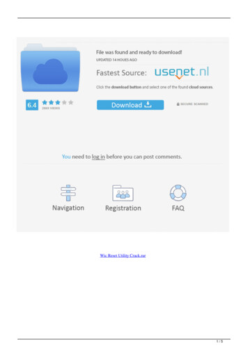
2. Boot Process when Power-onReset ReleaseConfig Read:VDD Input:Inte rnal OS CLVR (No Trim)PORProgram CounterStartInternal nPORLVI RESETBor LVR RESETBBIT (for Config)undefine00 01 02BIT (for Reset)undefine00 01 02Configure ReadInternal RESETb0A 0B0E 0F14 ms ( 20%) @ Internal OSC16 ms ( 20%) @ Internal OSCProgram Counter000000010002Figure 1. Boot Process when Power onNote) BIT count, Configure Read Time, and Internal ResetB Time may be different for each device.When the ABOV M8051 device reaches the POR voltage ( ①), the internal clock starts to operate andthe built-in analog block prepares to initialize the device. When the VDD voltage rises to the LVR voltage(②), the Internal Reset state inside the device is released and the BIT (Basic Interval Timer) Count startsfor configure read. In this case, there is an inaccuracy because the LVR voltage is not applied to theinternal reference LDO trimming, and the VDD rising slew rate needs to be limited within a certain rangefor correct operation in design. The pre-trim LVR voltage may vary from device to device, but is usuallywithin 1.4V to 2.0V. This value is adjusted to factory tested Trim value in Configure Read ( ③).ABOV SemiconductorV1.0 2018-07-06- 4 of 11 -
Configure read (③) and reset release (④) operate based on BIT (Basic Interval Timer) value from LVRpoint (②) instead of current VDD voltage value. Therefore, if the VDD rising slew rate of the intervalfrom LVR (②) to Configure read (③) (⑦ in Figure 1) is less than about 0.025V / ms, erroneous operationmay occur. This problem occurs because the Configure read does not meet the flash read voltagerequired to set the factory test trim value and internal register initialization value. If you have a slowVDD rising slew rate in POR in your application system, you can prevent the malfunction by delayingthe LVR reset release (②) by reinforcing circuit to increase slew rate or by adding RC filter to externalreset pin.Also, by setting a sufficiently high LVIR (Low voltage Indicate reset), reset can be generated whenVDD is below a certain voltage, and the reset release can be delayed until the LVIR voltage is exceeded.However, this method is used as an auxiliary protection measure because the inaccuracy to the LVIRvoltage is higher than usual when the Configure read is not performed normally.(TA -40 C 85 C, VSS 0V)TYPMAXUnitParameterSymbolConditionsMINPOR Release LevelVDD Voltage RisingTimePOR CurrentVPOR––1.1–VtR0V to 2.0V0.05–30.0V/msIPOR––0.2–uATable 1. Example of Power-on Reset CharacteristicsABOV SemiconductorV1.0 2018-07-06- 5 of 11 -
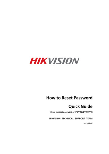
3. H/W design guide to prevent abnormal PORIn the Power-on Boot Process of the ABOV M8051 device, the three types of ports except I / O needto be managed. This terminal is VDD / GND which is directly powered, OCD terminal (DSCL, DSDA)used for Device Write and Debugging, and External Reset terminal used for external RESET input.3.1 VDD/GNDFor the microprocessor and other devices in the system to function correctly, it is also necessary tomonitor the supply voltage during operations. Voltage drops or glitches on the power supply lines, cancause unwanted changes in the internal registers, which can lead to instructions being incorrectlyexecuted, incorrect output signals and errors in the operations results. If noise is applied to the VDDrising slope due to external factors during the POR, the microprocessor may malfunction because themicroprocessor continues to operate and does not recognize that the voltage has fallen below thethreshold due to the internal RC time constants. Therefore, VDD / GND requires a power capacitor forVDD drop and a decoupling capacitor for high frequency noise. Normally, electrolytic / tantalumcapacitors of 10uf / 9V or more are recommended for power capacitors and multilayer ceramiccapacitors of 0.1uF or more are recommended for decoupling capacitors. Decoupling capacitors shouldbe placed as close as possible to the microprocessor.DeviceThis 0.1uF capacitor shouldbe within 1cm from the VDDpin of MCU on the PCBlayout.VDDVSS0.1uFVDDVCC0.1uF DCPowerThe MCU power line (VDD and VSS)should be separated from the highcurrent part at a DC power node onthe PCB layout.Figure 2. Recommended Power circuit part when using DC power.ABOV SemiconductorV1.0 2018-07-06- 6 of 11 -
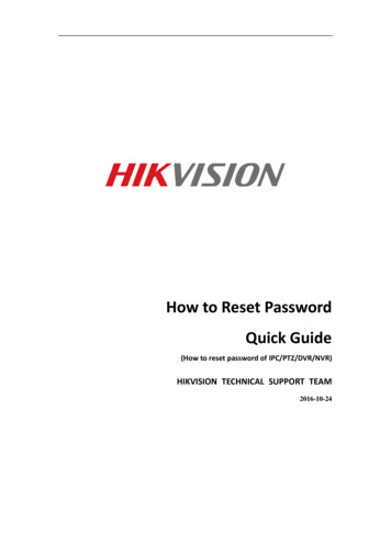
When an application uses AC power, it may be more susceptible to noise in the transient state, andadditional circuit reinforcement may be required.SMPS SideVCCMCU SideVDDSMPSR1DeviceVSSC1C2C31. The C1 capacitor is to flatten out the voltage of the SMPS power, VCC.Recommended C1: 470uF/25V more.2. The R1 and C2 are the RC filter for VDD and suppress the ripple of VCC.Recommended R1: 10Ω - 20ΩRecommended C2: 47uF/25V moreThe R1 and C2 should be as close by the C3 as possible.3. The C3 capacitor is used for temperature compensation because an electrolytic capacitorbecomes worse characteristics at low temperature.Recommended C3: ceramic capacitor 2.2uF moreThe C3 should be within 1cm from VDD pin of MCU on the PCB layout.4. The above circuit is recommended to improve noise immunity (EFT, Surge, ESD, etc) when theSMPS supplies the VDD of MCU.Figure 3. Recommended Power circuit part when using AC power.ABOV SemiconductorV1.0 2018-07-06- 7 of 11 -
3.2 OCD Port (DSCL, DSDA)Internal nPORLVI RESETBor LVR RESETBTest ModeControl ResetDSCLDSDAConfigure ReadInternal RESETb14 ms ( 20%) @ Internal OSC16 ms ( 20%) @ Internal OSCTEST MODE(OCD Mode)Figure 4. Test Mode (OCD mode) SequenceThe OCD port is used for flash program writing and device debugging. The device has a section thatdetermines whether to use it in that mode of POR. This is done when the internal reset is cleared andwaiting to clear Configure Read and Internal Reset. If the internal reset is cleared and DSCL and DSDAwait for a period of time from internal pull-up 'high' to 'low', the internal controller for entering test modeis initialized. Then, when DSCA and DSCA appointed communication, the test mode is entered.As described above, OCD port is a port for special purpose. Even if it is used as Normal GPIO in UserProgram, it is necessary to limit the state to prevent malfunction during POR. Therefore, it isrecommended to connect Pull-up Resistor to the outside of OCD Port and to fix OCD Port input to VDD/ GND at POR. If it is difficult to apply pull-up on the circuit, install at least 0.1uf bypass capacitor toprevent Floating state at POR. However, if you install a bypass cap, you can not use on board writingand OCD Debugger.ABOV SemiconductorV1.0 2018-07-06- 8 of 11 -
3.3 External ResetThe External Reset pin can be set in the Configure option, and can be set during Flash write in theWrite device and OCD mode.Figure 5. Example of option selectionExternal RESETB is internally input via the Schmitt trigger circuit. The reset pin is applied when it iskept 'low' for 10us or more within the operating range. After having stabilization time of about 10 20msfrom the recognition time of RESETB, it transmits the signal for resetting the actual MCU to the inside.Min10usExternalRESETVIH MAXVIL MINStabilizationTimeInternalRESETB5 OscillatorClocksMCUProgramSTARTFigure 6. External Reset TimeExternal RESETB at POR operates as Initial Value until Configure Read. If the initial value is EnableRESETB and the input is 'Low' with External RESETB, the Device will remain in the Internal RESETstate until the corresponding Pin becomes 'High'.ABOV SemiconductorV1.0 2018-07-06- 9 of 11 -
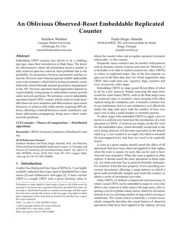
VDVccVDDDRCMCURESETBPower-up VccRC constant, withoutparallel diode, filters outfast voltage undershoots.VRCReset Input VTHInternal ResetbInputExample circuit 1VccVDDRCMCURESETBPOR VccPower-up VccVRCReset Input VTHC high C lowInternal ResetbInputExample circuit 2VccVDDI/OMCUCRESETB/ I/OExample circuit 3POR VccPower-up VccConfig.ReadVRCReset Input VTHGPIOInternal ResetbInputFigure 7. External Reset Pin CircuitEven if the initial value is Disable RESETB, it affects Internal Reset prior to RESET. Therefore, whenusing the pin as GPIO, 0.1uF should be mounted like Figure7 example circuit 3. This prevents noisefrom being applied to the corresponding pins during POR, and to prevent the reset circuit frommalfunction.When used as an external RESETB, an RC filter can be added to the corresponding pin to increasethe reset stabilization time when the POR is rising. (Figure 7. example circuit 2) However, the responseto fast undershoot may be weak due to the time constant of the RC delay. If the power fluctuation dueto the in-rush current of the power source part of the application is severe at the time of POR, theresponse time according to the power change can be improved by using the R-C-diode filter (Figure 7.example circuit 1).ABOV SemiconductorV1.0 2018-07-06- 10 of 11 -
Table of contentsRevision history . 21.Overview . 32.Boot Process when Power-on . 43.H/W design guide to prevent abnormal POR . 63.1VDD/GND . 63.2OCD Port (DSCL, DSDA) . 83.3External Reset . 9ABOV SemiconductorV1.0 2018-07-06- 11 of 11 -
additional circuit reinforcement may be required. SMPS VCC C1 C2 Device VDD R1 C3 VSS 1. The C1 capacitor is to flatten out the voltage of the SMPS power, VCC. Recommended C1: 470uF/25V more. 2. The R1 and C2 are the RC filter for VDD and suppress the ripple of VCC. Recommended R1: 10Ω - 20Ω Recommended C2: 47uF/25V more