Transcription
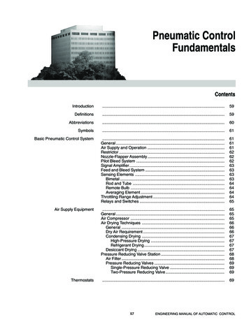
PNEUMATIC CONTROL FUNDAMENTALSPneumatic ons.59Abbreviations.60Symbols.61Basic Pneumatic Control System.General .Air Supply and Operation .Restrictor .Nozzle-Flapper Assembly .Pilot Bleed System .Signal Amplifier .Feed and Bleed System .Sensing Elements .Bimetal .Rod and Tube .Remote Bulb .Averaging Element .Throttling Range Adjustment .Relays and Switches .616161626262636363636464646465Air Supply Equipment.General .Air Compressor .Air Drying Techniques .General .Dry Air Requirement .Condensing Drying .High-Pressure Drying .Refrigerant Drying .Desiccant Drying .Pressure Reducing Valve Station .Air Filter .Pressure Reducing Valves .Single-Pressure Reducing Valve .Two-Pressure Reducing Valve INEERING MANUAL OF AUTOMATIC CONTROL
PNEUMATIC CONTROL FUNDAMENTALSControllers.General .Temperature Controllers .Humidity Controllers .Pressure Controllers .Sensor-Controller Systems .Pneumatic Controllers .Proportional-Integral (PI) Controllers .Controller Adjustments .Pneumatic Sensors .Velocity Sensor-Controller .7070717171727272727373.Actuators .General .Spring Ranges .Control Valves .Dampers .747474747576Relays and Switches.Switching Relay .Snap Acting Relay .Lockout Relay .High-Pressure Selector Relay .Low-Pressure Selector Relay .Load Analyzer Relay .Capacity Relay .Reversing Relay .Averaging Relay .Positive-Positioning Relay .Ratio Relay .Pneumatic Potentiometer .Hesitation Relay .Electrical Interlocking Relays .Electric-Pneumatic Relay .Pneumatic-Electric Relay .Electronic-Pneumatic Transducer .Pneumatic Switch .Manual Positioning Switch .7777787879797980808080818182828282838384Pneumatic Control Combinations.General .Sequence Control .Limit Control .Manual Switch Control .Changeover Control for Two-Pressure Supply System .Compensated Control System .Electric-Pneumatic Relay Control .Pneumatic-Electric Relay Control .Pneumatic Recycling Control .84848585868787878888Pneumatic Centralization.89Pneumatic Control System Example.Start-Stop Control Sequence .Supply Fan Control Sequence .Return Fan Control Sequence .Warm-up/Heating Coil Control Sequence .Mixing Damper Control Sequence .Discharge Air Temperature Control Sequence .Off/Failure Mode Control Sequence .9090929292939494Actuators and Final Control ElementsENGINEERING MANUAL OF AUTOMATIC CONTROL58
PNEUMATIC CONTROL FUNDAMENTALSINTRODUCTIONwith relatively simple equipment.— Pneumatic equipment is suitable where explosionhazards exist.— The installed cost of pneumatic controls and materialsmay be lower, especially where codes require that lowvoltage electrical wiring for similar electric controls berun in conduit.— Quality, properly installed pneumatic equipment isreliable. However, if a pneumatic control system requirestroubleshooting or service, most building-maintenancepeople have the necessary mechanical knowledge.This section provides basic information on pneumatic controlsystems and components commonly used to control equipmentin commercial heating and air conditioning applications. Theinformation in this section is of a general nature in order toexplain the fundamentals of pneumatic control. Some termsand references may vary between manufacturers (e.g., switchport numbers).Pneumatic control systems use compressed air to operateactuators, sensors, relays, and other control equipment.Pneumatic controls differ from other control systems in severalways with some distinct advantages:— Pneumatic equipment is inherently proportional but canprovide two-position control when required.— Many control sequences and combinations are possibleDEFINITIONSActuator: A mechanical device that operates a final controlelement (e.g., valve, damper).Controlled variable: The quantity or condition that is measuredand controlled (e.g., temperature, relative humidity,pressure).Authority (Reset Authority or Compensation Authority):A setting that indicates the relative effect acompensation sensor input has on the main setpoint(expressed in percent).Controller: A device that senses the controlled variable orreceives an input signal from a remote sensingelement, compares the signal with the setpoint, andoutputs a control signal (branchline pressure) to anactuator.Branch line: The air line from a controller to the controlleddevice.Differential: A term that applies to two-position devices. Therange through which the controlled variable must passin order to move the final control element from one tothe other of its two possible positions. The differencebetween cut-in and cut-out temperatures, pressures, etc.Branchline pressure (BLP): A varying air pressure signalfrom a controller to an actuator carried by the branchline. Can go from atmospheric to full main linepressure.Compensation changeover: The point at which thecompensation effect is reversed in action and changesfrom summer to winter or vice versa. The percent ofcompensation effect (authority) may also be changedat the same time.Direct acting (DA): A direct-acting thermostat or controllerincreases the branchline pressure on an increase inthe measured variable and decreases the branchlinepressure on a decrease in the variable. A direct-actingactuator extends the shaft on an increase in branchlinepressure and retracts the shaft on a decrease inpressure.Compensation control: A process of automatically adjustingthe control point of a given controller to compensatefor changes in a second measured variable such asoutdoor air temperature. For example, the hot deckcontrol point is reset upward as the outdoor airtemperature decreases. Also know as “reset control”.Discharge air: Conditioned air that has passed through a coil.Also, air discharged from a supply duct outlet into aspace. See Supply air.Final control element: A device such as a valve or damperthat acts to change the value of the manipulatedvariable. Positioned by an actuator.Compensation sensor: The system element which senses avariable other than the controlled variable and resetsthe main sensor control point. The amount of thiseffect is established by the authority setting.Control point: The actual value of the controlled variable(setpoint plus or minus offset).59ENGINEERING MANUAL OF AUTOMATIC CONTROL
PNEUMATIC CONTROL FUNDAMENTALSMeasuring element: Same as sensing element.Reverse acting (RA): A reverse-acting thermostat or controllerdecreases the branchline pressure on an increase inthe measured variable and increases the branchlinepressure on a decrease in the variable. A reverse-actingvalve actuator retracts the shaft on an increase inbranchline pressure and extends the shaft on adecrease in pressure.Mixed air: Typically a mixture of outdoor air and return airfrom the space.Sensing element: A device that detects and measures thecontrolled variable (e.g., temperature, humidity).Modulating: Varying or adjusting by small increments. Alsocalled “proportional”.Sensor: A device placed in a medium to be measured orcontrolled that has a change in output signal relatedto a change in the sensed medium.Main line: The air line from the air supply system to controllersand other devices. Usually plastic or copper tubing.Manipulated variable: Media or energy controlled to achievea desired controlled variable condition.Offset: A sustained deviation between the actual systemcontrol point and its controller setpoint under stableoperating conditions. Usually applies to proportional(modulating) control.Sensor Span: The variation in the sensed media that causesthe sensor output to vary between 3 and 15 psi.Setpoint: The value on the controller scale at which thecontroller is set (e.g., the desired room temperatureset on a thermostat). The desired control point.Proportional band: As applied to pneumatic control systems,the change in the controlled variable required tochange the controller output pressure from 3 to 13psi. Usually expressed as a percentage of sensor span.Supply air: Air leaving an air handling system.Thermostat: A device that responds to changes in temperatureand outputs a control signal (branchline pressure).Usually mounted on a wall in the controlled space.Reset control: See compensation control.Restrictor: A device in an air line that limits the flow of air.Throttling range: Related to proportional band, and expressedin values of the controlled variable (e.g., degrees,percent relative humidity, pounds per square inch)rather than in percent.Return air: Air entering an air handling system from theoccupied space.ABBREVIATIONSThe following port abbreviations are used in drawings ofrelays and controllers:B — BranchC — CommonE — ExhaustM — MainO — Normally connected*X — Normally disconnected*P — Pilot (P1 and P2 for dual-pilot relays)S — Sensor (S1 and S2 for dual-input controllers)N.C. — Normally closedN.O. — Normally openENGINEERING MANUAL OF AUTOMATIC CONTROL* The normally connected and common ports are connectedon a fall in pilot pressure below the relay setpoint, and thenormally disconnected port is blocked. On a rise in pilotpressure above the relay setpoint, the normally disconnectedand common ports are connected and the normallyconnected port is blocked. Refer to Figure 37 in RELAYSAND SWITCHES.60
PNEUMATIC CONTROL FUNDAMENTALSSYMBOLSMAIN AIR SUPPLYMORFIXED POINTMORRESTRICTORFULCRUMNOZZLEPIVOT POINTC1082BASIC PNEUMATIC CONTROL SYSTEMIn a typical control system, the final control element (a valveor a damper) is selected first because it must produce the desiredcontrol results. For example, a system designed to control theflow of water through a coil requires a control valve. The typeof valve, however, depends on whether the water is intendedfor heating or cooling, the water pressure, and the control andflow characteristics required. An actuator is then selected tooperate the final control element. A controller and relayscomplete the system. When all control systems for a buildingare designed, the air supply system can be sized and designed.GENERALA pneumatic control system is made up of the followingelements:— Compressed air supply system— Main line distribution system— Branch lines— Sensors— Controllers— Actuators— Final control elements (e.g., valves, dampers)AIR SUPPLY AND OPERATIONA basic pneumatic control system consists of an air supply,a controller such as a thermostat, and an actuator positioninga valve or damper (Fig. 1).The main line air supply is provided by an electrically drivencompressor pumping air into a storage tank at high pressure(Fig. 2). A pressure switch turns the compressor on and off tomaintain the storage tank pressure between fixed limits. Thetank stores the air until it is needed by control equipment. Theair dryer removes moisture from the air, and the filter removesoil and other impurities. The pressure reducing valve (PRV)typically reduces the pressure to 18 to 22 psi. For two-pressure(day/night) systems and for systems designed to change fromdirect to reverse acting (heating/cooling), the PRV switchesbetween two pressures, such as 13 and 18 psi. The maximumsafe air pressure for most pneumatic controls is 25 psi.TO OTHERCONTROLLERSTHERMOSTATCOMPRESSEDMAINAIR SUPPLYSYSTEMM BBRANCHACTUATORVALVEC2353Fig. 1. Basic Pneumatic Control System.AIRSUPPLYINThe controller receives air from the main line and regulatesits output pressure (branchline pressure) as a function of thetemperature, pressure, humidity, or other variable. Thebranchline pressure from the controller can vary from zero tofull mainline pressure. The regulated branchline pressureenergizes the actuator, which then assumes a positionproportional to the branchline pressure applied. The actuatorusually goes through its full stroke as the branchline pressurechanges from 3 psi to 13 psi. Other pressure ranges UREGAGESFILTERPRESSUREREDUCINGVALVEMAIN AIR TOPNEUMATICCONTROLSYSTEMC2616-1Fig. 2. Compressed Air Supply System.61ENGINEERING MANUAL OF AUTOMATIC CONTROL
PNEUMATIC CONTROL FUNDAMENTALSFrom the PRV, the air flows through the main line to thecontroller (in Figure 1, a thermostat) and to other controllersor relays in other parts of the system. The controller positionsthe actuator. The controller receives air from the main line at aconstant pressure and modulates that pressure to providebranchline air at a pressure that varies according to changes inthe controlled variable, as measured by the sensing element.The controller signal (branchline pressure) is transmitted viathe branch line to the controlled device (in Figure 1, a valveactuator). The actuator drives the final control element (valve)to a position proportional to the pressure supplied by thecontroller.To create a branchline pressure, a restrictor (Fig. 3) isrequired. The restrictor and nozzle are sized so that the nozzlecan exhaust more air than can be supplied through the restrictorwhen the flapper is off the nozzle. In that situation, thebranchline pressure is near zero. As the spring tension increasesto hold the flapper tighter against the nozzle, reducing the airescaping, the branchline pressure increases proportionally.When the spring tension prevents all airflow from the nozzle,the branchline pressure becomes the same as the mainlinepressure (assuming no air is flowing in the branch line). Thistype of control is called a “bleed” control because air “bleeds”continuously from the nozzle.When the proportional controller changes the air pressureto the actuator, the actuator moves in a direction and distanceproportional to the direction and magnitude of the change atthe sensing element.With this basic mechanism, all that is necessary to create acontroller is to add a sensing element to move the flapper asthe measured variable (e.g., temperature, humidity, pressure)changes. Sensing elements are discussed later.RESTRICTORPILOT BLEED SYSTEMThe restrictor is a basic component of a pneumatic controlsystem and is used in all controllers. A restrictor is usually adisc with a small hole inserted into an air line to restrict theamount of airflow. The size of the restrictor varies with theapplication, but can have a hole as small as 0.003 inches.The pilot bleed system is a means of increasing air capacityas well as reducing system air consumption. The restrictor andnozzle are smaller in a pilot bleed system than in a nozzleflapper system because in a pilot bleed system they supply aironly to a capacity amplifier that produces the branchlinepressure (Fig. 4). The capacity amplifier is a pilot bleedcomponent that maintains the branchline pressure in proportionto the pilot pressure but provides greater airflow capacity.NOZZLE-FLAPPER ASSEMBLYThe nozzle-flapper assembly (Fig. 3) is the basic mechanismfor controlling air pressure to the branch line. Air supplied tothe nozzle escapes between the nozzle opening and the flapper.At a given air supply pressure, the amount of air escaping isdetermined by how tightly the flapper is held against the nozzleby a sensing element, such as a bimetal. Thus, controlling thetension on the spring also controls the amount of air escaping.Very little air can escape when the flapper is held tightly againstthe PERCAPACITYAMPLIFIERC1085Fig. 4. Pilot Bleed System with Amplifier Relay.NOZZLESPRINGThe pilot pressure from the nozzle enters the pilot chamberof the capacity amplifier. In the state shown in Figure 4, no airenters or leaves the branch chamber. If the pilot pressure fromthe nozzle is greater than the spring force, the pilot chamberdiaphragm is forced down, which opens the feed valve andallows main air into the branch chamber. When the pilotpressure decreases, the pilot chamber diaphragm rises, closingRESTRICTORMBRANCHAIR SUPPLYC1084Fig. 3. Nozzle-Flapper Assembly with Restrictor.ENGINEERING MANUAL OF AUTOMATIC CONTROL62
PNEUMATIC CONTROL FUNDAMENTALSthe feed valve. If the pilot chamber diaphragm rises enough, itlifts the bleed valve off the feed valve disc, allowing air toescape from the branch chamber through the vent, thusdecreasing the branchline pressure. Main air is used only whenbranchline pressure must be increased and to supply the verysmall amount exhausted through the SSUREPRESSURECHAMBERSIGNAL AMPLIFIEREXHIn addition to the capacity amplifier, pneumatic systems alsouse a signal amplifier. Generally, modern amplifiers usediaphragms for control logic instead of levers, bellows, andlinkages.MBLEED VALVEFEED VALVEC2382-1Fig. 5. Feed and Bleed System.A signal amplifier increases the level of the input signal andprovides increased flow. This amplifier is used primarily insensor-controller systems where a small signal change from asensor must be amplified to provide a proportional branchlinepressure. The signal amplifier must be very sensitive andaccurate, because the input signal from the sensor may changeas little as 0.06 psi per degree Fahrenheit.A force applied by the sensing element at the sensor inputpoint is opposed by the setpoint adjustment spring and lever.When the sensing element pushes down on the lever, the leverpivots on the bleed ball and allows the feed ball to rise, whichallows main air into the chamber. If the sensing element reducesits force, the other end of the lever rises and pivots on the feedball, and the bleed ball rises to exhaust air from the system.The sensor can be any sensing element having enough forceto operate the system.Another use for a signal amplifier is to multiply a signal bytwo to four times so a signal from one controller can operateseveral actuators in sequence.SENSING ELEMENTSFEED AND BLEED SYSTEMBIMETALThe “feed and bleed” (sometimes called “non bleed”) systemof controlling branchline pressure is more complicated thanthe nozzle-flapper assembly but theoretically uses less air. Thenozzle-flapper system exhausts some air through the nozzlecontinually, whereas the feed and bleed system exhausts aironly when the branchline pressure is being reduced. Sincemodern nozzle-flapper devices consume little air, feed andbleed systems are no longer popular.A bimetal sensing element is often used in a temperaturecontroller to move the flapper. A bimetal consists of two stripsof different metals welded together as shown in Figure 6A. Asthe bimetal is heated, the metal with the higher coefficient ofexpansion expands more than the other metal, and the bimetalwarps toward the lower-coefficient metal (Fig. 6B). As thetemperature falls, the bimetal warps in the other direction(Fig. 6C).The feed and bleed system consists of a feed valve thatsupplies main air to the branch line and a bleed valve thatexhausts air from the branch line (Fig. 5). Each valve consistsof a ball nested on top of a tube. Some pneumatic controllersuse pressure balance diaphragm devices in lieu of springs andvalves. A spring in the tube continually tries to force the ballup. The lever holds the ball down to form a tight seal at theend of the tube. The feed and bleed valves cannot be open atthe same time.A. CALIBRATION TEMPERATUREB. INCREASED TEMPERATUREC. DECREASED TEMPERATUREMETALS:HIGH COEFFICIENT OF EXPANSIONLOW COEFFICIENT OF EXPANSIONC1087Fig. 6. Bimetal Sensing Element.63ENGINEERING MANUAL OF AUTOMATIC CONTROL
PNEUMATIC CONTROL FUNDAMENTALSA temperature controller consists of a bimetal element linkedto a flapper so that a change in temperature changes the positionof the flapper. Figure 7 shows a direct-acting thermostat(branchline pressure increases as temperature increases) inwhich the branchline pressure change is proportional to thetemperature change. An adjustment screw on the spring adjuststhe temperature at which the controller operates. If the tensionis increased, the temperature must be higher for the bimetal todevelop the force necessary to oppose the spring, lift theflapper, and reduce the branch pressure.diaphragm chamber. The expansion causes the diaphragm padto push the pin toward the lever, which moves the flapper tochange the branchline pressure.DIAPHRAGM PADLIQUID FILLPINCAPILLARYBULBCONTROLLERCONTACT POINT FORTHROTTING RANGEADJUSTMENTBIMETALDIAPHRAGM CHAMBERFig. 9. Remote-Bulb Temperature Sensor.Remote-bulb temperature sensors are used in bleed-typecontrollers. Capillary length of up to 2.5 meters are normallyused for inserting the bulb in duct, tank, or AVERAGING ELEMENTFig. 7. Temperature Controller withBimetal Sensing Element.The averaging-element sensor is similar to the remote-bulbsensor except that it has no bulb and the whole capillary is themeasuring element. The long, flexible capillary has a slightlywider bore to accommodate the equivalent liquid fill that isfound in a remote-bulb sensor. The averaging-element sensoraverages temperatures along its entire length and is typicallyused to measure temperatures across the cross section of aduct in which two air streams may not mix completely.Averaging element sensors are used to provide an input signalto a controller.ROD AND TUBEThe rod-and-tube sensing element consists of a brass tubeand an Invar rod, as shown in Figure 8. The tube expands andcontracts in response to temperature changes more than therod. The construction of the sensor causes the tube to movethe rod as the tube responds to temperature changes. One endof the rod connects to the tube and the other end connects tothe flapper spring to change the force on the flapper.THROTTLING RANGE ADJUSTMENTA controller must always have some means to adjust thethrottling range (proportional band). In a pneumatic controller,the throttling range is the change at the sensor required tochange the branchline pressure 10 psi. The setpoint is usuallyat the center of the throttling range. For example, if thethrottling range of a temperature controller is 4F and thesetpoint is 72F, the branchline pressure is 3 psi at 70F, 8 psi at72F, and 13 psi at 74F for a direct acting controller.TUBECONNECTIONTO FLAPPERSPRINGRODC1089Fig. 8. Rod-and-Tube Insertion Sensor.In all pneumatic systems except the sensor-controller system,the throttling range is adjusted by changing the effective lengthof a lever arm. In Figure 7, the throttling range is changed bymoving the contact point between the bimetal and the flapper.(For information on adjusting the throttling range in a sensorcontroller system, see SENSOR-CONTROLLER SYSTEMS.)On a rise in temperature, the brass tube expands and draws therod with it. The rod pulls on the flapper spring which pulls theflapper closed to the nozzle. The flapper movement decreasesthe air-bleed rate, which increases branchline pressure.REMOTE BULBRELAYS AND SWITCHESThe remote-bulb sensing element has as measuring elementmade up of a capillary and bulb filled with a liquid or vapor(Fig. 9). On and increase in temperature at the bulb, the liquidor vapor expands through the capillary tubing into theENGINEERING MANUAL OF AUTOMATIC CONTROLRelays are used in control circuits between controllers andcontrolled devices to perform a fu
Pneumatic controls differ from other control systems in several ways with some distinct advantages: — Pneumatic equipment is inherently proportional but can provide two-position control when required. — Many control sequences and combinations are possible with relatively simple equipment. — Pneumatic equipment is suitable where explosion
