Transcription
xxZZZRMD5000Rackmount 20-02
Copyright Tektronix. All rights reserved. Licensed software products are owned by Tektronix or its subsidiariesor suppliers, and are protected by national copyright laws and international treaty provisions.Tektronix products are covered by U.S. and foreign patents, issued and pending. Information in this publicationsupersedes that in all previously published material. Specifications and price change privileges reserved.TEKTRONIX and TEK are registered trademarks of Tektronix, Inc.Contacting TektronixTektronix, Inc.14150 SW Karl Braun DriveP.O. Box 500Beaverton, OR 97077USAFor product information, sales, service, and technical support:In North America, call 1-800-833-9200.Worldwide, visit www.tektronix.com to find contacts in your area.
Service Safety SummaryOnly qualified personnel should perform service procedures. Read this ServiceSafety Summary and the General Safety Summary in the product service manualor the instruction manual.Do Not Service Alone. Do not perform internal service or adjustments of thisproduct unless another person capable of rendering first aid and resuscitation ispresent.To prevent the instrument and rack from falling onto the operator, two or moreinstallers should install the instrument into the rack cabinet. After completing theinstallation procedure, the installers should verify that the instrument and rackcabinet will not tip forward while the instrument is in the extended position.Disconnect Power. To avoid electric shock, switch off the instrument power, thendisconnect the power cord from the mains power.Use Care When Servicing With Power On. Dangerous voltages or currents mayexist in this product. Disconnect power and disconnect test leads before removingprotective panels, soldering, or replacing components.To avoid electric shock, do not touch exposed connections.RMD5000 Rackmount Kit Instructions1
Kit DescriptionKit DescriptionThese instructions describe the installation of the rackmount kit to your standardbench-top instrument. The rackmount kit is a collection of parts that, onceinstalled, configure the instrument for mounting in a fixed position into a standard19-inch equipment rack. (See Table 1.) If you require the instrument to slide inand out of the rack, order the optional slide kit. (See Table 2.)ProductsDPO4000B Series All Serial NumbersMSO4000B Series All Serial NumbersMDO4000B Series All Serial NumbersDPO5000/B Series All Serial NumbersMSO5000/B Series All Serial NumbersKit Parts ListThe parts included in this rackmount kit are listed below. (See Table 1.) (SeeFigure 1 on page 3.)Table 1: RMD5000 Rackmount kitItemQuantityPart numberDescription11 each407-5531-XXPLATE, MOUNTING; RACKMOUNT LEFT21 each407-5532-XXPLATE, MOUNTING; RACKMOUNT RIGHT31 each407-5534-XXPLATE, SUPPORT; RACKMOUNT TOP41 each407-5533-XXPLATE, SUPPORT; RACKMOUNT BOTTOM51 each426-2636-XXPLATE, SUPPORT; RACKMOUNT FRONT61 each016-2037-XXHARDWARE KIT7—1 each016-2038-XXCOMMON HARDWARE KIT1 each075-1020-XXTECH MANUAL: INSTRUCTIONS, RACKMOUNT KITOptional AccessoriesTable 2: Optional AccessoriesPart numberDescription351-1095-XXSLIDE ASSY; PAIR, W/STD HARDWARE KIT AND REAR BRACKET2RMD5000 Rackmount Kit Instructions
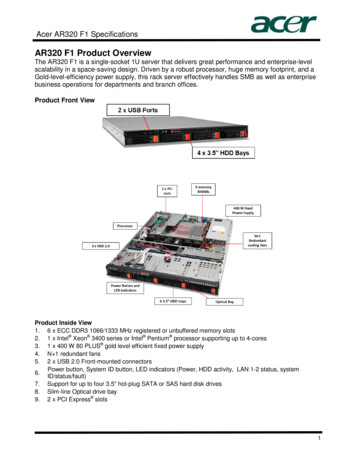
Kit DescriptionFigure 1: Rackmount kit parts (part appearance may vary)Figure 2: Optional slide assembly kitRMD5000 Rackmount Kit Instructions3
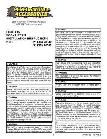
Kit DescriptionWarranted CharacteristicsWhen the instrument is installed according to the instructions in this document,the rack-mounted instrument meets all warranted characteristics listed in theinstrument specification except for those listed. (See page 5, EnvironmentalRequirements.) Instruments mounted using methods other than those described inthese instructions may not meet their warranted characteristics.See the specifications for your instrument model for tables of the warrantedcharacteristics.Cooling air enters on the bottom and right sides as shown. (See Figure 3.) Youmust provide adequate cool air to meet the ambient temperature requirementslisted. (See Table 3 on page 5.)Figure 3: Instrument cooling4RMD5000 Rackmount Kit Instructions
Kit DescriptionEnvironmental RequirementsThe following environmental characteristics supersede those listed in thespecifications and performance verification sections of the manual for yourinstrument.Table 3: Warranted einside rack cabinetOperating 10 C to 45 C ( 50 F to 113 F)Nonoperating–22 C to 60 C (–7.6 F to 140 F)ShockOperating andnonoperating20 g, 11 ms, half sine, each axis, 3 drops eachClearance RequirementsThe rack in which the rack adapted instrument is mounted must provide thefollowing clearance requirements:A minimum of 8.75 in (222.25 mm) of vertical spaceA minimum width of 17.72 in (450.09 mm) between the left- and right-frontrails in the rackA minimum depth of 12.75 in (323.85 mm)CAUTION. Adhering to these clearance requirements provides the rack-mountedinstrument with sufficient clearance for air circulation and accommodation of thepower cord and mounting hardware. Failure to provide these clearances canresult in overheating and can cause instrument faults or failure.RMD5000 Rackmount Kit Instructions5
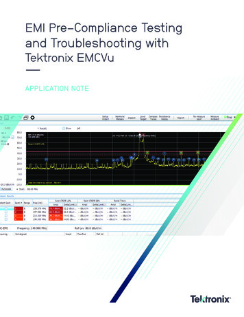
Kit DescriptionFigure 4: Instrument with rack adapter installed6RMD5000 Rackmount Kit Instructions
Installation InstructionsInstallation InstructionsThis section contains the procedures needed to rackmount a DPO4000B,MSO4000B, MDO4000B, DPO5000/B, or MSO5000/B series instrument.Minimum Tool and Equipment ListThe following tools are required to attach the rack-adapter kit hardware, installcabling hardware, and mount the rack-adapted instrument into a standardequipment cabinet. All tools are standard tools that are readily available.Table 4: Tools required for rackmount installationNameDescriptionScrewdriver handle(magnetic)Accepts 1/4-inch hexagonal head driver tipsNo. 2 Phillips orPoziDriv tipPhillips or PoziDriv-driver tip for number 2 size screw headsT-10 TORX tipTORX-drive tip for T-10 size screw heads (flat-head)T-15 TORX tipTORX-drive tip for T-15 size screw headsT-20 TORX tipTORX-drive tip for T-20 size screw heads1/4-inch wrenchWrench or nut driver can be used to install slidesTorque driver6.5 in long shaft; accepts 1/4-inch hexagonal head driver tipsThese instructions are for qualified service personnel who are familiar withservicing the product. If you need further details for disassembling or reassemblingthe product, refer to the appropriate product manual. Contact your nearestTektronix Service Center or Tektronix Factory Service for installation assistance.WARNING. To prevent the rackmounted instrument from tipping forward onto theoperator, install the instrument so that the operator will be able to access all of itsrear-panel connectors without pushing down on the instrument.Verify that the rack does not become unstable with the instrument fully extended.Do not leave the instrument extended when finished accessing the rear panel.WARNING. To avoid electric shock, disconnect the power cord from the mainspower before removing the cover. Failure to do so could result in personal injuryor death.RMD5000 Rackmount Kit Instructions7
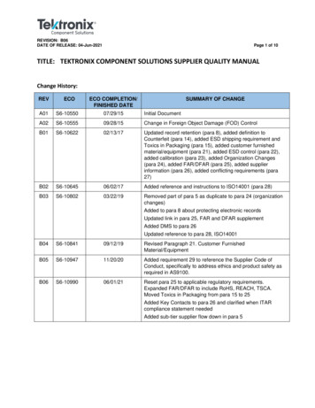
Installation InstructionsRemoveEquipment Required: Screwdriver handle with T-15 tip.This procedure prepares the instrument for installation of the rackmount parts.NOTE. Retain all parts removed from the instrument for later use. Some of thoseparts will be reinstalled as you perform this rack conversion; store the remainderin case reconversion to a standard instrument configuration is desired at a latertime.1. Disconnect the power cord from the rear of the instrument.2. Remove the four T-15 TORX screws that secure the rear cover to the frontcase assembly. (See Figure 5.)3. Remove the rear cover.Figure 5: Removing the rear case cover8RMD5000 Rackmount Kit Instructions
Installation InstructionsInstallThis section describes mounting the rackmount parts to the instrument.Equipment Required: Torque driver with T-15 and T-20 tips.1. Assemble the left and right mounting plates to the bottom support plateusing six 6-32 x 0.250 inch pan head T-15 TORX-drive screws tightened to8 in-lb. (See Figure 6.)NOTE. The bottom support plate has holes to facilitate mounting optionalaccessories. You can use screws or nylon straps to mount accessories.Figure 6: Assembling the left and right mounting platesRMD5000 Rackmount Kit Instructions9
Installation Instructions2. Fasten the front support plate to the left and right mounting plates with six6-32 x 0.250 inch pan head T-15 TORX-drive screws, lining up the dimples inthe back support plate with the slots in the mounting plates. (See Figure 7.)Tighten screws to 8 in-lb.Figure 7: Assembling the rackmount front support plate3. Install the two handles using four 10-32 x 0.25 inch pan head T-20TORX-drive screws tightened to 16 in-lb. Handles should curve towardsthe sides of the instrument.10RMD5000 Rackmount Kit Instructions
Installation Instructions4. Install the top support plate; note the orientation for the different instruments:(See Figure 8.)For MDO/MSO/DPO4000B instruments, install the top support plate with theflange toward the front of the enclosure so that the “DPO4000B” stampingon the plate is visible.For MSO/DPO5000/B instruments, install the top support plate with theflange toward the back of the enclosure.Figure 8: Installing the top support plateRMD5000 Rackmount Kit Instructions11
Installation Instructions5. Install the instrument into the rackmount enclosure using six 6-32 x 0.250inch flat-head T-15 TORX-drive screws tightened to 8 in-lb. (See Figure 9.)Figure 9: Installing the instrument in the enclosure12RMD5000 Rackmount Kit Instructions
Installation InstructionsThis completes the installation of the standard rack-adapter hardware included inthis kit. The instrument is now ready to mount in a fixed location, to the front railsof a standard instrument rack.To mount the instrument in a fixed location, proceed to Finishing the Installation.(See page 21, Finishing the Installation.)If you require the instrument to slide in and out of the instrument rack, order theoptional slide assembly kit and use the instructions that follow. (See page 14,Mount the Track Hardware (Optional).)RMD5000 Rackmount Kit Instructions13
Installation InstructionsMount the Track Hardware(Optional)Install the optional slide assembly kit as follows:1. Remove the front section of each of the two tracks. (See Figure 10.)Figure 10: Preparing the tracks for mounting2. Install the front left- and right-side track sections on the instrument using four6-32 x 0.250 inch pan head T-15 TORX-drive screws tightened to 8 in-lb.(See Figure 11.)Figure 11: Installing the left- and right-side track sections14RMD5000 Rackmount Kit Instructions
Installation InstructionsWARNING. To ensure that the rackmount track locks, make sure the track buttonlatches are oriented correctly: the right-side latch is located toward the bottomof the rackmount panel and the left-side latch is located toward the top of therackmount panel. (See Figure 12.) If the button latches are not oriented correctlythe instrument could slide from the rack, which could cause personal injury ordamage to the instrument.Figure 12: Track orientationThis completes the installation of the slide hardware to the instrument. Tocomplete the installation, proceed to: Rackmount the Rack- Adapted Instrument.(See page 16.)RMD5000 Rackmount Kit Instructions15
Installation InstructionsRackmount the Rack-Adapted InstrumentThis procedure assembles and installs the slide-out tracks in the equipment rack,and then installs the rack-adapted instrument in the rack.The slide-out tracks permit the rack-adapted instrument to be extended out of therack for rear-panel and connector maintenance without removing the instrumentfrom the rack.WARNING. To prevent the rackmounted instrument from tipping forward onto theoperator, install the instrument so that the operator will be able to access all of itsrear devices without pushing down on the instrument.Verify that the rack does not become unstable with the instrument fully extended.Do not leave the instrument extended when finished accessing the rear panel.Install Track Assembly andInstrument into the RackEquipment Required: One screwdriver handle, one number two PoziDriv tip,and one torque driver.NOTE. The rack hardware kit contains hardware for mounting the instrument inseveral configurations. Not all of the hardware in the kit will be needed.A standard equipment rack has rails with universal hole spacing. If you use arack with other than universal hole spacing, you may have to drill additionalmounting holes in the rack.1. Assemble the slide-out track:a. Measure the distance between the front and rear rail of the equipment rack.16RMD5000 Rackmount Kit Instructions
Installation InstructionsFigure 13: Slide-out track assembliesb. Align the rear bracket to the right slide-out track as shown. (SeeFigure 13.) Note that the rear bracket has multiple pairs of mount-throughholes. When aligning the bracket and track, be sure to select a pair of holesthat mount the rear bracket so that the flange-to-flange distance matchesthe distance between the front rail and rear rail measured in step a.c. Using a screwdriver with a number two PoziDriv tip, secure the rearbracket to the right slide-out track using two screws (10-32) and a bar nutas illustrated. Leave the screws loose so that the overall length of theslide-out track assembly can be adjusted when installing it in the rack.d. Repeat steps b and c to assemble the left slide-out track assembly.RMD5000 Rackmount Kit Instructions17
Installation Instructions2. Mount the slide-out track assemblies, using the slide drawer hardware listedin the kit parts list:a. Select the mounting position in rack: Select two 0.5 inch-spaced holes inthe front rail. Verify that the 4.36 inch and 10.500 inch clearances existrelative to those mounting holes. (See Figure 14.)Figure 14: Vertical clearances for rack installation (left-front rail shown)18RMD5000 Rackmount Kit Instructions
Installation Instructionsb. Select the mounting method according to rack type:To mount the slide-out tracks with their front and rear flanges outside ofthe front and rear rails, use the mounting method A shown when doingsubstep c. (See Figure 15.) Add a bar nut to the installation only if therails have untapped holes.To mount with front and rear flanges inside of rails, use the mountingmethod B. This mounting method assumes untapped holes.Figure 15: Installing slide-out track assemblies in rack (top view)c. Install in rack: Using the method and hardware determined fromsubstep b, secure the right slide-out track assembly to its front and rearrails. The screws should be lightly seated so mounting can be adjustedlater.RMD5000 Rackmount Kit Instructions19
Installation Instructionsd. Fix the length of the slide-out track assembly: Tighten the screws leftloose in step 1, substep c, applying 28 inch-lb of torque, to fix the front torear flange spacing of the slide-out track assembly.e. Mount the left slide-out track assembly: Repeat substeps c through d tomount the left slide-out track assembly.3. Mount the instrument in the rack:WARNING. To prevent the instrument from tipping or dropping onto the installers,two or more people should install this instrument into the rack cabinet.After completing the installation procedure, the installers should verify that theinstrument and rack cabinet will not tip forward while the instrument is in theextended position.a. Install the instrument:Working from the front of the rack, slide the inner track of each slide-outtrack assembly until it extends out the front of the rack. Continue to slidethem out until they lock.Insert the left and right tracks that extend from the rear of the instrumentinto the ends of the tracks just extended. Make sure the tracks mounted onthe instrument slip inside the inner tracks extended earlier.Slide the instrument backward until it stops.Push to release the button latches, located on the outside of each track,and continue to slide the instrument all the way into the cabinet.b. Level the rackmounted instrument:Tighten the four screws that were left loose at the rear of the rack when youdid step 2, substep c, and then pull the instrument partially out of the rack.Be sure that the four screws that were left loose at the front of the rackare loose enough to allow the slide-out track assemblies to seek theirnormal positions.Retighten the four screws and push the instrument all the way into therack. If the tracks do not slide smoothly, readjust the level using themethod just detailed.When leveling is completed, tighten the 10-32 screws using 28 inch-lb oftorque.20RMD5000 Rackmount Kit Instructions
Installation InstructionsFinishing the InstallationIf you intend to mount the instrument to the rack without slides, use this procedureto complete your installation. If you mounted the slide track kit to the instrument,you should also perform this step to secure the instrument to the rack.WARNING. To prevent the rack-mounted instrument from sliding forward andcausing personal injury or instrument damage, always secure the instrument tothe rack if the rack is moved (for example, if the rack is repositioned or relocatedto another room).Secure the instrument to the rack using four 10-32 x 0.625 in screws andrectangular washer spacers as shown. (See Figure 16.)Figure 16: Securing the instrument to the rack* End of document *RMD5000 Rackmount Kit Instructions21
Kit Description These instructions describe the installation of the rackmount kit to your standard bench-top instrument. The rackmount kit is a collection of parts that, once installed, configure the instrument for mounting in a fixed position into a standard 19-inch equipment rack. (See Table 1.) If you require the instrument to slide in