Transcription
Pixels Wall MountedDesign and Installation GuideDecember 2012
On the cover: Pixels mural shown with GE Tetra Power Grid during installation.For more information go to gelightingsolutions.com
Design and Installation GuidePixels wall-mounted Celebration panels fromUSG offer a turnkey system for displaying the uniqueperforated imagery art that Pixels makes possible.PagesPlanning Your System2Overview— Wall-Mounted SystemsPixels PanelsDesign ElementsSurface-Mounted tallationFrame-Mounted lationAppendixFor More Information30Shop DrawingsUSG/GE Power Grid System ModulesTechnical ServiceWeb Site800 USG.4YOUusg.com1 Pixels Design and Installation Guide
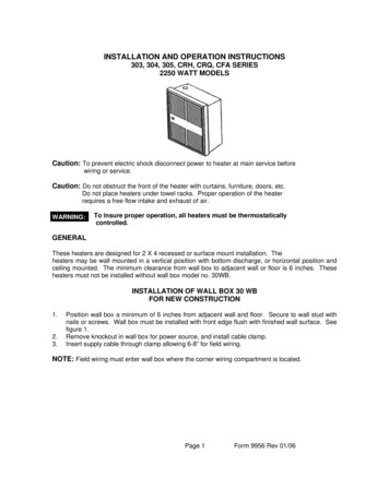
System OverviewPixels Wall-Mounted ApplicationsFeaturesCelebration panels and Celebration panels with Pixels imagery can be mounted to thevertical surface in two ways: directly to the surface using wall mount backer board system,or away from the vertical surface leaving a “cavity” in which to mount light sources for backlighting the image. Here are examples of each application.Surface MountedThis backer board system is simple in both design and application while providing a hard surfacedirectly behind the Celebration panel thus improving durability.2 Pixels Design and Installation Guide
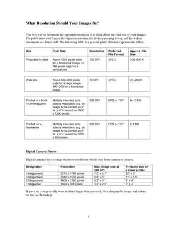
System OverviewPixels Wall-Mounted ApplicationsFrame MountedThe backlit system is also simplified in that it uses standard Fineline suspension – only mounted to thewall thus being quite familiar to contractors.[photo image}On the pages that follow, further explanation of the systems will clarify, in detail, how each can be usedeffectively depending on the design criteria and desired result. An example of Pixels frame-mounted backlit installation with GE Tetra PowerGrid is on displayat GE Lighting & Electrical Institute at historic Nela Park, Cleveland, OH (photo above)3 Pixels Design and Installation Guide
System OverviewDesign ElementsShapeThe overall shape of a wall-mounted system is determined by the size of the panels and theirconfiguration and relationship to one another.Available panel sizes are– 28 x 28– 28 x 48– 28 x 68Panels28 x 28 Pixels Celebration Panel28 x 48 Pixels Celebration Panel28 x 68 Pixels Celebration PanelNote: The Pixels image and design process itself is detailed in the Pixels Design Guide, IC566. Through thatprocess the panels are ordered separately from the wall mount system.4 Pixels Design and Installation Guide
System OverviewDesign ElementsThe Pixels panels can be arranged in any number of creative ways. As long as the 28 moduledimension is honored, almost any configuration can be achieved including altering the shapeof the frame itself.Sample Configurations68 x 48 System2' x 2'2' x 2'2' x 2'2' x 4'2' x 2'2' x 2'2' x 2'88 x 48 System2' x 2'2' x 4'2' x 2'2' x 4'2' x 2'5 Pixels Design and Installation Guide2' x 2'2' x 4'2' x 4'
System OverviewDesign ElementsSample Configurations68 x 68 Systems2' x 2'2' x 4'2' x 6'2' x 2'2' x 2'2' x 2'2' x 2'2' x 2'2' x 2'2' x 2'2' x 2'2' x 4'2' x 4'2' x 2'2' x 2'2' x 2'There is no limitation to the finished size of the system. The above examples are only to show theflexibility of panel layout and frame configuration.6 Pixels Design and Installation Guide
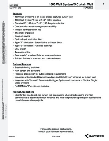
System OverviewDesign ElementsPhotos can be used as is or combined with copy or graphics. Also see Pixels Design Guide (IC566)for a further understanding of Pixels graphics capabilities.28 x 48 configuration7 Pixels Design and Installation Guide
Surface-Mounted SystemComponentsIn addition to the Pixels Celebration panels (see page 4), the following components are uniqueto the surface-mounted system.Surface-Mounted Backer Boards28 x 28 (WMBB24)28 x 48 (WMBB48)28 x 68 (WMBB72)Construction DetailBacker Board Edge Prfilepre-drilledfastener holeadhesive backedpoly bumper8 Pixels Design and Installation Guide
Surface-Mounted SystemComponentsEdge TrimBacker Board Aluminum TrimFastenerWall-Dog FastenerNote: Wall-Dog is a trademark of Powers Fasteners, Inc. For more information please visit www.powers.com9 Pixels Design and Installation Guide
Surface-Mounted SystemConstructionThe surface-mounted system consists of backer panels that are installed edge-to-edgedirectly to the wall surface.PIXELS panel orCELEBRATIONS panelaluminum trimdrywall screwbacker boardABC10 Pixels Design and Installation Guide
Surface-Mounted SystemConstructionConstruction DetailsA. Panel Intersectionadhesive backedpoly bumperdrywall screwB. Perimeter EdgePIXELS panel orCELEBRATIONS panelbacker boardbacker boarddrywall screwPIXELS panel orCELEBRATIONS panelaluminum trimSHEETROCK gypsum panelSHEETROCK gypsum panelC. CornerPIXELS panel orCELEBRATIONS panel1/4" reveal11 Pixels Design and Installation Guidealuminumtrim
Surface-Mounted SystemInstallationNote: These installation instructions cover the basic rectangular design using 28 x 28 panels.There will be more complex designs that require a different or more complex grid layout.Step 1Establish a vertical and horizontalcontrol line with a laser or chalkline that is at the intersection of4 panels.Step 2In order to assure proper horizontalalignment, it is recommended that atemporary ledger board be installedon the horizontal control line theentire length of the finished wallinstallation.12 Pixels Design and Installation Guide
Surface-Mounted SystemInstallationStep 3Begin the installation of the backerpanels at the intersection of thevertical control line and the ledgerboard. Fasten to wall through thepredrilled holes using appropriateanchor fasteners.Step 4Each consecutive panel will contactthe previous panel along the entirelength of the vertical leg. With thecontact area free of debris, continuethe installation in both directionsworking from the control line out.13 Pixels Design and Installation Guide
Surface-Mounted SystemInstallationStep 5Using a straight edge on the verticaledge of the previously installedbacker panel, align the second roll ofbacker panels with the first.Step 6Once the upper panels are allinstalled, remove the ledger boardand install the bottom row of panelsaligning them vertically as describedin the previous step.14 Pixels Design and Installation Guide
Surface-Mounted SystemInstallationStep 7Install the pre-mitered friction-fit triminto the panel kerf on all four sides.Screws may be loosened on backerpanel perimeter to fit bottom leg oftrim behind panel. Once all the trimis in place, re-tighten the perimeterscrews.Step 8Gently pre-fit Pixels panels inany order onto the backer panels.Using the heel of your hand, seatthe Pixels panel starting from topleft uppermost corner to the rightuppermost corner. Work downfrom both corners to the bottomuntil all edges are seated.Installation DetailPIXELS panel orCELEBRATIONS panel1/4" revealaluminumtrim15 Pixels Design and Installation Guide
Surface-Mounted SystemInstallationStep 9The finished system.16 Pixels Design and Installation Guide
Frame-Mounted Backlit SystemComponentsIn addition to the Pixels Celebration panels (see page 4), the following components are uniqueto the frame-mounted backlit system.FramePre-Mitered Frame SegmentOptions49 Frame Profile69 Frame Profile4"6"3/4"3/4"AccessoriesElite Splice Plate17 Pixels Design and Installation GuidePerimeter Frame Attachment Clip (WMPFAC)
Frame-Mounted Backlit SystemComponentsGridFineline DXF Main Tee, Pre-CutFineline DXF Cross TeeGrid Attachment Clip (WMGAC)Grid Support Bracket (WMGSB) 18 Pixels Design and Installation Guide
Frame-Mounted Backlit SystemComponentsBacklit OptionFoam GasketFastenersWall-Dog FastenerNote: Wall-Dog is a trademark of Powers Fasteners, Inc. For more information please visit www.powers.com19 Pixels Design and Installation Guide
Frame-Mounted Backlit SystemConstructionPIXELS panel orCELEBRATIONS panelPIXELS Wall MountPre-Mitered FrameADXF main teeDXF cross teesplice plategrid supportbracketBDgrid attachment clipperimeter frameattachment clipCE20 Pixels Design and Installation Guide
Frame-Mounted Backlit SystemConstructionConstruction DetailsA. Typical Perimeter EdgePIXELS wall mountpre-mitered frameB. Corner SplicePIXELS panel orCELEBRATIONS panelfriction fit foam toseal off light leaksaround perimeterPIXELS frameteessplice plateSHEETROCK gypsum panelC. Perimeter Attachment ClipsPIXELS wall mountpre-mitered frameD. Grid Support Panel IntersectionPIXELS panel orCELEBRATIONS panelPIXELS panel orCELEBRATIONS panelteegrid attachment clipteesperimeter frameattachment clipSHEETROCK gypsum panelSHEETROCK gypsum panelE. CornerrevealPIXELS panel orCELEBRATIONS panelPIXELS frame21 Pixels Design and Installation Guidegrid supportbracketbracket screwattached
Frame-Mounted Backlit SystemInstallation – Perimeter FrameNote: These installation instructions cover the basic rectangular design using 28 x 28 panels.There will be more complex designs that require a different or more complex grid layout.Establish the bottom corner of theinstallation to be at least 8 inchesoff the floor and use a cross laserto determine both vertical andhorizontal control lines.vertical reference lineStep 18" min.horizontafloorStep 2Install perimeter frame attachmentclips (WMPFAC) inside of thetrim per shop drawing supplied.Pre-assemble the corner splice intothe bottom horizontal trim piece.Installation Detail22 Pixels Design and Installation Guidel reflineerence line
Frame-Mounted Backlit SystemInstallation – Perimeter FrameStep 3Align lower edge of trim withreference control line and screwattach to wall using appropriatefasteners and anchors as necessary.(Wall-Dog fasteners work well)Step 4Install adjacent vertical trim intothe corner splice and attach to wallaligning with vertical laser line.23 Pixels Design and Installation Guide
Frame-Mounted Backlit SystemInstallation – Perimeter FrameStep 5Continue building perimeter trimframe per shop drawings. Verify thatthe frame is square by measuringdiagonally corner to corner. If notsquare, adjust accordingly. FRAMEMUST BE SQUARE!Lighting nce the perimeter trim frame is in place, lighting shall be installed per local codes and suppliedOshop drawings. The GE Tetra PowerGrid system is an excellent choice for Pixels backlit systems.See USG/GE Designed Together to Work Together program on page 32 for more information.24 Pixels Design and Installation Guide
Frame-Mounted Backlit SystemInstallation — Fineline Grid Step 1Install grid attachment clip (WMGAC)into perimeter trim per shop drawingssupplied.Step 2Beginning at the left side, attach maintee section to the grid attachment clip(WMGAC) and bend tabs to lock inplace.Installation Detail25 Pixels Design and Installation Guide
Frame-Mounted Backlit SystemInstallation — Fineline Grid Step 3Attach cross tees per the shopdrawing and locate the next main teesection.Step 4Attach cross tees to the top andbottom trim using WMGAC1.Installation Detail26 Pixels Design and Installation Guide
Frame-Mounted Backlit SystemInstallation — Fineline Grid Step 5Continue this procedure from left toright until reaching the trim on theright side.Step 6Install wall mount grid supportbrackets (WMGSB) on main teesper shop drawings.27 Pixels Design and Installation Guide
Frame-Mounted Backlit SystemInstallation — Fineline Grid Step 7Tuck foam into space between gridand trim to block light leaks. Be sureto push foam all the way to the faceof the trim.Installation DetailPIXELS wall mountpre-mitered framePIXELS panel orCELEBRATIONS panelfriction fit foam toseal off light leaksaround perimeterteesSHEETROCK gypsum panelwood backingStep 8Assure the system is square.28 Pixels Design and Installation Guide
Frame-Mounted Backlit SystemInstallation — Pixels PanelsStep 9Install Celebration or Pixel panelsper shop drawings.Installation DetailrevealPIXELS panel orCELEBRATIONS panelPIXELS frameStep 10The finished system.29 Pixels Design and Installation Guide
AppendixSample Shop DrawingsBill of MaterialsGrid and Panels30 Pixels Design and Installation Guide
AppendixSample Shop DrawingsLightingView From Front31 Pixels Design and Installation Guide
AppendixUSG GEDesigned Together to Work TogetherUSG PixelsTMWall-Mounted Systemswith GE Tetra PowerGridGE Tetra PowerGridUSG PixelsWall-Mounted SystemsGE Tetra PowerGrid Driver(transformer)GE Tetra 32 Pixels Design and Installation GuideUSG Pixels Wall-Mounted Systemswww.usg.com1-800-950-3839
Prouct LiteratureData sheet: IC605Design guide: IC566Check sheet: IC607TrademarksThe following are trademarks ofUSG Interiors, LLC. or a relatedcompany: Pixels, Celebration,DXF, Fineline, USG, USG inNoticestylized letters. GE LightingWe shall not be liable forSolutions, LLC is a subsidiary ofincidental and consequentialthe General Electric Company.damages, directly or indirectly The GE brand logo, Tetra aresustained, nor for any losstrademarks of the Generalcaused by application of these Electric Company. 2012goods not in accordance withGE Lighting Solutions, LLC.current printed instructions or Wall-Dog is a trademark offor other than the intended use. Powers Fasteners, Inc.Our liability is expressly limitedSafety First!to replacement of defectiveFollow good safety/industrialgoods. Any claim shall behygiene practices duringdeemed waived unless madeinstallation. Wear appropriatein writing to us within thirtypersonal protective equipment.(30) days from date it was orRead MSDS and literature beforereasonably should have beenspecification and installation.discovered.Manufactured byUSG Interiors, LLC550 West Adams StreetChicago, IL .comusgdesignstudio.comIC606/12-12 2012, USG Interiors, LLCPrinted in U.S.A.
3 Pixels Design and Installation Guide System Overview Pixels Wall-Mounted Applications Frame Mounted The backlit system is also simplified in that it uses standard Fineline suspension - only mounted to the wall thus being quite familiar to contractors. [photo image} On the pages that follow, further explanation of the systems will clarify, in detail, how each can be used