Transcription
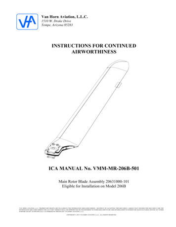
Van Horn Aviation, L.L.C.1510 W. Drake DriveTempe, Arizona 85283INSTRUCTIONS FOR CONTINUEDAIRWORTHINESSICA MANUAL No. VMM-MR-206B-501Main Rotor Blade Assembly 20631000-101Eligible for Installation on Model 206BVAN HORN AVIATION, L.L.C. PROPRIETARY RIGHTS ARE INCLUDED IN THE INFORMATION DISCLOSED HEREIN. RECIPIENT, BY ACCEPTING THIS DOCUMENT, AGREES THAT NEITHER THIS DOCUMENT NOR THEINFORMATION DISCLOSED HEREIN NOR ANY PART THEREOF SHALL BE REPRODUCED OR TRANSFERRED TO OTHER DOCUMENTS OR USED OR DISCLOSED TO OTHERS FOR MANUFACTURING OR FOR ANY OTHERPURPOSE EXCEPT AS SPECIFICALLY AUTHORIZED IN WRITING BY VAN HORN AVIATION, L.L.C.COPYRIGHT 2015 VAN HORN AVIATION, L.L.C., ALL RIGHTS RESERVED
INSTRUCTIONS FOR CONTINUED AIRWORTHINESSNo. VMM-MR-206B-501Page 2 of 15Revision: CREVISIONSREVDATEDESCRIPTIONAPPROVEDInitial ReleaseJVHN/C01/27/16A02/02/16Updated section 4, airworthinessschedule. Added bushing and grip plateinspections. Updated figure 62-1.JVHB02/10/16Updated section 4, airworthinessschedule.JVHC04/29/16Updated section 4, airworthinessschedule.JVHVAN HORN AVIATION L.L.C.
INSTRUCTIONS FOR CONTINUED AIRWORTHINESSNo. VMM-MR-206B-501Page 3 of 15Revision: CTABLE OF CONTENTSREVISIONS . 2TABLE OF CONTENTS . 3CHAPTER O - INTRODUCTION . 4CHAPTER 4 – AIRWORTHINESS LIMITATIONS . 5CHAPTER 5 – INSPECTION/CHECK REQUIREMENTS. 6CHAPTER 11 – PLACARDS AND DECALS . 12CHAPTER 62 – MAIN ROTOR BLADE . 12VAN HORN AVIATION L.L.C.
INSTRUCTIONS FOR CONTINUED AIRWORTHINESSNo. VMM-MR-206B-501Page 4 of 15Revision: CCHAPTER 0 - INTRODUCTION0.1 SCOPEThis manual contains information, descriptions, and instructions essential for the continuedairworthiness of the Van Horn Aviation L.L.C. 20631000-101 Main Rotor Blade Assembly.0.2 ARRANGEMENTThis manual follows the Airline Transport Association (ATA) specification 100 numberingsystem where practical.0.3 UNITS OF MEASUREMENTAll measurements, tolerances, and other numbers referenced in this manual will be in Englishunits.0.4 CHANGES TO THE ICA0.4.1 Changes to text and tables, including new material on added pages shall be indicatedby a vertical bar in the outer margin extending close to the entire area of the materialaffected.0.4.2 Please send any comments or corrections to Van Horn Aviation L.L.C., 1510 WestDrake Drive, Tempe, AZ 85283 USA. Or call 01-480-483-4202.0.5 DISTRIBUTION0.5.1 The ICA will be shipped with the original purchase of a 20631000-101 main rotor bladeassembly.0.5.2 The ICA can be found on Van Horn Aviation’s website atwww.vanhornaviation.com.VAN HORN AVIATION L.L.C.
INSTRUCTIONS FOR CONTINUED AIRWORTHINESSNo. VMM-MR-206B-501Page 6 of 15Revision: CCHAPTER 5 – INSPECTION/CHECK REQUIREMENTS5.1. PRE-FLIGHT CHECKNo.Requirements1.Visually check the main rotor blades forany visible damage such as cracks, irworthiness CriteriaSee 5.8 DAMAGE LIMITS5.2. 100 ( /- 10 hour tolerance) HOUR INSPECTION AND ANNUALLYNo.Inspection RequirementsAirworthiness Criteria1.Check the general condition of the rotorblade. Check for skin dents, scratches, orSee 5.8 DAMAGE LIMITSblisters. Check the trailing edge for nicksor delaminations.2.Examine tip balance weights for security.3.Inspect the abrasion strips for wear, cracks Contact Van Horn Aviation if anyand edge voids.discrepancies found.Make sure weightsmove/turn easily.donot5.3 300 ( /- 30 hour tolerance) HOUR INSPECTIONNo.1.5.4Perform dynamic balance of main rotor.Airworthiness CriteriaBalance to .20 IPS or lower.1,400 ( /- 30 hour tolerance) HOUR INSPECTIONNo.1.Inspection RequirementsInspection RequirementsAirworthiness CriteriaContact Van Horn Aviation if anyInspect grip plate assemblies, root plates, discrepancies found and for gripand bushings for cracks.plateassemblyinstallationinstructions.VAN HORN AVIATION L.L.C.
INSTRUCTIONS FOR CONTINUED AIRWORTHINESSNo. VMM-MR-206B-5015.5Page 7 of 15Revision: C2,800 ( /- 30 hour tolerance) HOUR INSPECTIONNo.Inspection RequirementsAirworthiness Criteria1.Remove and replace 20631020-101 & 103 grip plate assemblies, 20631391-1 and20631392-1 bushings. Replace allinstallation hardware. Inspect entire mainrotor blade assembly for cracks, voids,blisters, or other damage. Inspect bushingholes thru blade. Inspect root plates forcracks.Contact Van Horn Aviation if anydiscrepancies found and for gripplateassemblyinstallationinstructions.5.6 SUDDEN STOPPAGE OR ACCELERATIONNo.1.Inspection RequirementsNo inspection requiredAirworthiness CriteriaRemove the rotor blades andreturn to Van Horn Aviation forevaluation.5.7 OVERSPEED – 107 PERCENT OR GREATERNo.1.2.Inspection RequirementsAirworthiness CriteriaFor main rotor overspeed above 107% upto 114% Inspect main rotor blades for anyvisible damage such as cracks, blisters,No defects For main rotor overspeed above 114%Inspect main rotor blades for any visibledamage such as cracks, blisters,delaminations, or local contour and No defects permitted.dimensionally check main rotor bladeattachment bushing for elongation inexcess of .0015 inch.VAN HORN AVIATION L.L.C.
INSTRUCTIONS FOR CONTINUED AIRWORTHINESSNo. VMM-MR-206B-501Page 8 of 15Revision: C5.8 OVERTORQUENo.Inspection RequirementsAirworthiness Criteria1.No inspection is required for overtorquesN/Abetween 100 to 110 percent.2.Overtorques 110 to 120 percent, Inspectthe main rotor blades for any visibledamage such as cracks, blisters,delaminations,orlocalcontour No defects permitted.deformation. If any of these conditionsexist, remove the rotor blades and return toVan Horn Aviation for evaluation.3.Overtorques above 120 percent require theinspections in Step 2 above at the time ofNo defects permitted.the overtorque and again after 25 hours ofoperation.5.9 LIGHTNING STRIKENo.1.Inspection RequirementsAirworthiness CriteriaScrap the blades if there is any evidence ofa lightning strike. Return the scraped N/Ablades to Van Horn Aviation for testing.VAN HORN AVIATION L.L.C.
INSTRUCTIONS FOR CONTINUED AIRWORTHINESSNo. VMM-MR-206B-501Page 9 of 15Revision: C5.10 DAMAGE LIMITS5.10.1 Damage DescriptionDamage may take the form of cracks, scratches, nicks, dents, disbonds, or voids. Limitsare provided for each of these types of damage. Damage exceeding these limits requireevaluation, and if possible, repair at an authorized FAA repair station. Contact VHA forrepair station recommendations.5.10.2 Abrasion StripsThree abrasion strips are used on the leading edge. The electroformed nickel inboardabrasion extends from near the inboard end of the blade to approximately STA 37.0.It over laps the stainless steel constant section abrasion strip which starts at STA 36.0and extends to STA 180.0. The electroformed nickel tip abrasion strip starts atapproximately STA 179.0 and extends to the blade tip. It overlaps the constant sectionabrasion strip. The criteria below applies to all three abrasion strips.a. Non-sharp dents not exceeding 0.050 inch are acceptable at any location.b. Sharp dents are not permitted.c. Punctures or cracks are not permitted.d. Tap test an area 1.0 inch either side of the dent for voids.e. Inspect for trailing edge disbond.f. If disbonds or voids exist, there is a possibility of underlying carbon fiber damage;therefore, evaluation at an approved FAA repair station is required. Contact VHAfor repair station recommendations.g. If there are no disbonds or voids, leave the dent exposed so it may be monitoredfor evidence of cracking in the future.h. If abrasion strip is worn thru because of erosion, send blade to an approvedFAA repair station for repair. Contact VHA for repair station recommendations.VAN HORN AVIATION L.L.C.
INSTRUCTIONS FOR CONTINUED AIRWORTHINESSNo. VMM-MR-206B-501Page 10 of 15Revision: C5.10.3 SkinImpact damage may progress from little evidence of external damage to puncturewith surrounding voids depending on impact force. In all cases of suspected skindamage, a tap test is required to determine extent of the damage.a. Voids are not allowed within 1.0 inch of the trailing edge.b. Voids not exceeding 1.0 inch diameter are acceptable at any spanwise location.c. If voids are detected, remove paint in the damaged area to check for broken fibers.Remove paint and primer only. Do not sand into skin plies.d. Broken fibers are not permitted. If broken fibers are detected, send blade to anauthorized FAA repair station for evaluation, and if possible, repair. ContactVHA for repair station recommendationse. Scratches, nicks, or fiber damage in the extreme trailing edge 0.10 deep or lessmay be blended out over a distance of at least 2.0 inches each side of the damage.See Figure 5-1 below.f. Damage at the tip trailing edge may be removed by blending up to a 1.0 inchradius at the tip. See Figure 5-1 below.Figure 5-1Tip and Trailing Edge Damage LimitsVAN HORN AVIATION L.L.C.
INSTRUCTIONS FOR CONTINUED AIRWORTHINESSNo. VMM-MR-206B-501Page 11 of 15Revision: C5.10.4 Spot RefinishingVHA finishes the main rotor blade using an epoxy surfacing film co-cured with the skin,epoxy paint primer, and a two stage top coat. First stage is a color coat. Second stage isclear.a. When preparing the blade for touch-up, do not sand into skin plies. Primer andsurfacing film is gray. Carbon/epoxy skin plies are black. Copper mesh lightningstrike protection is bonded over the skin.b. A polyurethane film co-cured with the skin protects the tapered tip from STA 180.0to the tip at STA 200.0. Paint erosion is permitted in this area so long as thepolyurethane film has not eroded exposing carbon/epoxy skin.c. Exposed carbon/epoxy skin not exceeding 0.50 inch aft of abrasion strip trailing edgemust be protected by at least one coat of epoxy primer within 25 flight hours ofexposure.d. Exposed carbon/epoxy skin exceeding 0.50 inch aft of abrasion strip trailing edgemust be protected by at least one coat of epoxy primer within 10 flight hours ofexposure. See Figure 5.2.e. Paint peeling may occur. Feather paint edges using 320 grit or finer abrasive paperto stop peeling. Touchup paint required for appearance only if black carbon/epoxyskin is not exposed. Touch up exposed skin with one coat of epoxy primer.f. Paint nicks and scratches require touchup paint for appearance only if blackcarbon/epoxy skin is not exposed. Touch up exposed skin with one coat of epoxyprimer.g. Paint touch-up may be performed using either a two stage or single stage method.Exact matching is difficult using single stage paint, so it is recommended using thismethod for small areas only. Single stage paint is DuPont Imron Elite SS SingleStage Color. Any aerospace quality polyurethane paint may be substituted. Use acompatible epoxy primer. Two stage paint is DuPont Imron Elite Basecoat Color usedwith DuPont Imron Elite 8840S Clearcoat.h. White paint (upper blade surface except tip) is DuPont color 786255.i. Black paint (lower blade surface) is DuPont color 99.j. Blue paint (tip upper surface) is DuPont color 7165.VAN HORN AVIATION L.L.C.
INSTRUCTIONS FOR CONTINUED AIRWORTHINESSNo. VMM-MR-206B-501Page 12 of 15Revision: CCHAPTER 11 – PLACARDS AND DECALSThere are no placards or decals associated with this STC.CHAPTER 62 – MAIN ROTOR BLADE62.1 DESCRIPTIONThe 20631000-101 main rotor blade is a composite and metallic structure incorporating theNASA-developed RC(4)-12(12% thick) rotor blade airfoil. This is a highly efficient laminarflow airfoil developed to have near zero pitching moments across a broad range of airspeeds.The blade radius and chord is the same as the existing production blade except that the tip ofthe blade is tapered to reduce noise and tip drag. The root fitting is machined titanium alloyplate fastened to the blade root using two .750-inch bolts. Stainless steel bushings are bondedinto the root of the blade. The basic blade section is fabricated using unidirectionalcarbon/epoxy tape and plain weave carbon/epoxy fabric with a rigid cell structural foam core.Span balance is accomplished using cylindrical weights bonded into a fiberglass/epoxy highpressure laminate sheet receptacle and threaded stainless steel screws in a fiberglass/epoxyhigh pressure laminate tip cap. Electroformed nickel and stainless steel abrasion strips areadded for erosion protection.Figure 62-1Main Rotor Blade DescriptionVAN HORN AVIATION L.L.C.
INSTRUCTIONS FOR CONTINUED AIRWORTHINESSNo. VMM-MR-206B-501Page 13 of 15Revision: C62.2 INSTALLATION20631000-101 main rotor blade assembly is eligible for installation on helicoptersmodified per T.B. 206-91-133 MAIN ROTOR HUB ASSEMBLY, P/N 206-001-100,CONFIGURATION OF, with the following hub configurations:206-011-100-011 small hub incorporating grip assembly 206-010-101-121206-011-100-017 small hub incorporating grip assembly 206-010-101-121206-011-100-021 small hub incorporating grip assembly 206-010-101-013 or -121206-011-100-all larger hub configurationsInstall the 20631000-101 main rotor blade according to the current FAA acceptedmaintenance manual for existing production main rotor blades 206-010-200-ALLexcept as follows:The 20631000-101 main rotor blade incorporates an alignment drive screw positionedon the upper surface of the blade 20 inches inboard of the tip. See figure 62-2. Tape thealignment cord over the alignment screw.Figure 62-2Main Rotor Blade Alignment MarkVAN HORN AVIATION L.L.C.
INSTRUCTIONS FOR CONTINUED AIRWORTHINESSNo. VMM-MR-206B-501Page 14 of 15Revision: C62.4 STATIC BALANCE OF MAIN ROTOR BLADESBalance the 20631000-101 main rotor blades according to the current FAA acceptedmaintenance manual for the existing production main rotor blade 206-010-200-ALL.62.3 DYNAMIC TRACKING AND BALANCING OF MAIN ROTOR BLADESThe 20631000-101 main rotor blade incorporates a different airfoil, different span andchord weight distribution, and the blade is stiffer. These differences have an effect onhow the blades respond to normal adjustments during tracking and balancing. Bladeresponse will be as predicted, but the magnitude of changes to adjustments may bedifferent depending upon the equipment used.NOTEIt is not recommended using the automated type of track andbalance equipment such as RADS-AT or other systems that rely onthe specific dynamics of metal production rotor blades. If RADSAT or similar system is the only system available, contact VHA forassistance.62.3.1 Dynamic BalancingDynamically balance the 20631000-101 main rotor blades according to the currentFAA accepted maintenance manual for the existing production main rotor blade 206010-200-ALL.NOTEDo not use the three tip weights for balance adjustment.62.3.2 Dynamic TrackingDynamically track 20631000-101 main rotor blades according to the current FAAaccepted maintenance manual for the existing production main rotor blade 206-010200-ALL with the following exceptions and recommended practices.a) The 20631000-101 main rotor blade has a single trim tab centered at bladestation 150.0. Use tracking instructions for blades with outboard trim tabonly.b) It is recommended using only pitch links for hover tracking. Use trim tabsfor forward flight tracking only.c) Use tool 206-CS-T001 for trim tab adjustments. This tool incorporates boththe tab bending tool and tab position indicator. Tab position is measured inthousands of an inch from neutral (0 deg. tab angle) position. Use 206-CST002 tracking tabs.d) It is recommended correcting an out of track condition by equally adjustingone blade up and the other down. Testing has shown that this provides thebest method for insuring a smooth track over large airspeed ranges.VAN HORN AVIATION L.L.C.
INSTRUCTIONS FOR CONTINUED AIRWORTHINESSNo. VMM-MR-206B-501Page 15 of 15Revision: C62.5 WEIGHT AND BALANCEThe weight of each 20631000-101 main rotor blade is recorded on each blade’shistorical record (log card). Adjust the helicopter’s weight and balance record asrequired.62.6 CLEANINGUse a soft cloth and non-caustic, non-abrasive cleaner to clean VHA composite mainrotor blades.62.7 GRIP PAD REPLACEMENTGrip pad 20631341-1 (see figure 6-3) may be replaced with Bell grip pad 206-010-233005. Install either the VHA or Bell grip pad according to the current FAA acceptedcomponent repair and overhaul (CR&O) manual for the existing production main rotorblade 206-010-200-ALL with the following exceptions and recommended practices.a) Titanium grip plate 20631321-1 is not shot peened. CR&O caution is N/A.62.8 WEAR PAD REPLACEMENTWear pad 20631342-1 (see figure 6-3) may be replaced with Bell wear pad 206-010242-003. Install either the VHA or Bell wear pad according to the current FAAaccepted component repair and overhaul (CR&O) manual for the existing productionmain rotor blade 206-010-200-ALL with the following exceptions and recommendedpractices.a) Titanium grip plate 20631321-1 is not shot peened. CR&O caution is N/A.b) Sweep check is not required.c) Blade alignment is required after wear pad replacement.62.9 GRIP PLATE ASSEMBLY REPLACEMENTContact VHA for 20631020-101, -103 grip plate assembly, 20631391-1 bushing, and20631392-1 bushing replacement.Figure 62-3Main Rotor Blade Root AssemblyVAN HORN AVIATION L.L.C.
method for small areas only. Single stage paint is DuPont Imron Elite SS Single Stage Color. Any aerospace quality polyurethane paint may be substituted. Use a compatible epoxy primer. Two stage paint is DuPont Imron Elite Basecoat Color used with DuPont Imron Elite 8840S Clearcoat. h. White paint (upper blade surface except tip) is DuPont .