Transcription
INSTALLATION MANUALTRUEfood service equipment, inc.tfmCONGRATULATIONS!You have just purchased the finest commercial refrigeratoravailable. You can expect many years of trouble-free operation.TABLE OF CONTENTSSAFETY INFORMATIONSafety Precautions1Proper Disposal, Connecting Electricity, & Adapter Plugs2INSTALLATIONOwnership, Uncrating, & How to Connect to Electricity3Wire Gauge Chart4Locating and Leveling5Installation of Legs or Castors6Sealing Cabinet to the Floor6TFM-29FLOPERATIONStartup7Mechanical Temperature Controls Sequence of Operation8MAINTENANCE, CARE, CLEANINGCleaning Condenser Coil13Important Warranty Information14Stainless Steel Equipment Care and Cleaning15WARRANTYWarranty16TFM-41FLINSTALLATION MANUALtfm – true freezer merchandiserTRUE FOOD SERVICE EQUIPMENT, INC.2001 East Terra Lane O’Fallon, Missouri 63366-4434(636)-240-2400 FAX (636)-272-2408 INT'L FAX (636)272-7546 (800)-325-6152Parts Department (800)-424-TRUE Parts Department FAX# (636)-272-9471Web: www.truemfg.com#975545 LM 6/15
TRUEwww.truemfg.comtfmNOTICE TO CUSTOMERLoss or spoilage of products in your refrigerator/freezer is not covered by warranty. In addition tofollowing recommended installation proceduresyou must run the refrigerator/freezer 24 hoursprior to usage.SAFETY INFORMATIONHow to Maintain Your True Refrigerator to Receive the Most Efficient and Successful Operation.You have selected one of the finest commercial refrigeration units made. It is manufactured under strict quality controls with only the bestquality materials available. Your TRUE cooler when properly maintained will give you many years of trouble-free service.WARNING: Use this appliance for its intended purpose as described in this Owner Manual.TO LOCATE REFRIGERANT TYPE, SEE SERIAL LABEL INSIDE CABINET. This cabinet may contain fluorinated greenhousegas covered by the Kyoto Protocol (please refer to cabinet’s inner label for type and volume, GWP of 134a 1,300. R404a 3,800).FOR HYDROCARBON REFRIGERATION ONLY (R-290) SEE BELOW: DANGER - Risk of fire or explosion. Flammable refrigerant used. Do not use mechanical devices to defrost refrigerator. Do notpuncture refrigerant tubing. DANGER - Risk of fire or explosion. Flammable refrigerant used. To be repaired only by trained service personnel. Do not puncturerefrigerant tubing. CAUTION - Risk of fire or explosion. Flammable refrigerant used. Consult repair manual/owner’s guide before attempting to servicethis product. All safety precautions must be followed. CAUTION - Risk of fire or explosion. Dispose of properly in accordance with federal or local regulations. Flammable refrigerant used. CAUTION - Risk of fire or explosion due to puncture of refrigerant tubing; follow handling instructions carefully. Flammable refrigerantused. CAUTION - Keep clear of obstruction all ventilation openings in the appliance enclosure or in the structure for building-in.SAFETY PRECAUTIONSWhen using electrical appliances, basic safety precautions should befollowed, including the following: This refrigerator must be properly installed and located inaccordance with the Installation Instructions before it is used. Do not allow children to climb, stand or hang on the shelvesin the refrigerator. They could damage the refrigerator andseriously injure themselves. Do not touch the cold surfaces in the freezer compartmentwhen hands are damp or wet. Skin may stick to theseextremely cold surfaces. Do not store or use gasoline or other flammable vapors andliquids in the vicinity of this or any other appliance. Do not storeexplosive substances such as aerosol cans with a flammablepropellant in this appliance.1 Keep fingers out of the “pinch point” areas; clearances betweenthe doors and between the doors and cabinet are necessarilysmall; be careful closing doors when children are in the area.Unplug the refrigerator before cleaning and making repairs.Setting temperature controls to the 0 position does notremove power to the light circuit, perimeter heaters, orevaporator fans.NOTE: We strongly recommend that any servicing be preformedby a qualified technician.
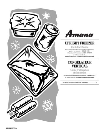
TRUEwww.truemfg.comtfmDANGERRISK OF CHILDENTRAPMENTPROPER DISPOSAL OF THE REFRIGERATORChild entrapment and suffocation are not problems of the past.Junked or abandoned refrigerators are still dangerous even if theywill sit for “just a few days.” If you are getting rid of your old refrigerator, please follow the instructions below to help prevent accidents.BEFORE YOU THROW AWAY YOUR OLDREFRIGERATOR OR FREEZER: Take off the doors. Leave the shelves in place so that children may not easily climbinside.APPLIANCE DISPOSALWhen recycling appliance please make sure that the refrigerants arehandled according to local and national codes, requirements andregulations.REFRIGERANT DISPOSALYour old refrigerator may have a cooling system that uses “OzoneDepleting” chemicals. If you are throwing away your old refrigerator,make sure the refrigerant is removed for proper disposal by a qualified service technician. If you intentionally release any refrigerants youcan be subject to fines and imprisonment under provisions of theenvironmental regulations.USE OF EXTENSION CORDSWARNING!HOW TO CONNECT ELECTRICITYDO NOT, UNDER ANY CIRCUMSTANCES, CUT ORREMOVE THE GROUND PRONG FROM THE POWERCORD. FOR PERSONAL SAFETY, THIS APPLIANCEMUST BE PROPERLY GROUNDED.The power cord from this appliance is equipped with a groundingplug which minimizes the possibility of electric shock hazard.Have the wall outlet and circuit checked by a qualified electrician tomake sure the outlet is properly grounded.If the outlet is a standard 2-prong outlet, it is your personal responsibility and obligation to have it replaced with the properly groundedwall outlet.The refrigerator should always be plugged into it’s own individualelectrical circuit, which has a voltage rating that matches the ratingplate.This provides the best performance and also prevents overloadingbuilding wiring circuits which could cause a fire hazard from overheated wires.Never unplug your refrigerator by pulling on the power cord. Alwaysgrip plug firmly and pull straight out from the outlet.Repair or replace immediately all power cords that have becomefrayed or otherwise damaged. Do not use a cord that shows cracksor abrasion damage along its length or at either end.When removing the refrigerator away from the wall, be careful notto roll over or damage the power cord.If supply power cord is damaged it should be replaced with originalequipment manufacture parts. To avoid hazard this should be doneby a qualified service technician.NEVER USE AN EXTENSION CORD! TRUE will not warranty any refrigerator that has been connected to an extension cord.USE OF ADAPTER PLUGSREPLACEMENT PARTSNEVER USE AN ADAPTER PLUG! Because of potential safetyhazards under certain conditions, we strongly recommend against theuse of an adapter plug. Component parts shall be replaced with like components. Servicing shall be done by authorized service personnel, tominimize the risk of possible ignition due to incorrect parts orimproper service. Lamps must be replaced by identical lamps only. If the supply cord is damaged, it must be replaced by a specialcord or assembly available from the manufacturer or its serviceagent.The incoming power source to the cabinet including any adaptersused must have the adequate power available and must be properlygrounded. Only adapters listed with UL should be used.NORTH AMERICA USE ONLY!NEMA plugsTRUE uses these types of plugs. If you do not have the right outlethave a certified electrician install the correct power source.NOTE: International plug configurations vary by voltage and 115/60/1NEMA-5-20R208-230/60/1NEMA-6-15R2
TRUEwww.truemfg.comtfmINSTALLATIONOWNERSHIPTo ensure that your unit works properly from the first day, it mustbe installed properly. We highly recommend a trained refrigerationmechanic and electrician install your TRUE equipment. The cost of aprofessional installation is money well spent.Before you start to install your TRUE unit, carefully inspect it forfreight damage. If damage is discovered, immediately file a claim withthe delivery freight carrier.TRUE is not responsible for damage incurred during shipment.UNCRATINGTOOLS REQUIRED Adjustable Wrench Phillips Screwdriver LevelThe following procedure is recommended for uncrating the unit:A. Remove the outer packaging, (cardboard and bubbles orStyrofoam corners and clear plastic). Inspect for concealeddamage. Again, immediately file a claim with the freight carrierif there is damage.B.Move your unit as close to the final location as possible beforeremoving the wooden skid.NOTE: Keys for coolers with door locks are located in warrantypackets.ELECTRIC INSTALLATION & SAFETYINFORMATION If the supply cord is damaged, it must be replaced by a specialcord or assembly available from the manufacturer or its serviceagent. Lamps must be replaced by identical lamps only. Appliance tested according to the climate classes 5 and 7temperature and relative humidity.ELECTRICAL INSTRUCTIONSA. Before your new unit is connected to a power supply, check theincoming voltage with a voltmeter. If anything less than 100% ofthe rated voltage for operation is noted, correct immediately.B. All units are equipped with a service cord, and must bepowered at proper operating voltage at all times. Refer tocabinet data plate for this voltage.TRUE RECOMMENDS THAT A SOLE USE CIRCUIT BEDEDICATED FOR THE UNIT.WARNING: Compressor warranties are void if compressor burnsout due to low voltage.WARNING: Power supply cord ground should not be removed!WARNING: Do not use electrical appliances inside the foodstorage compartments of the appliances unless they are of the typerecommended by the manufacturer.NOTE: To reference wiring diagram, remove front louvered grill,wiring diagram is positioned on the inside cabinet wall.NOTE: When loading product do not exceed product load linelabeled on the interior wall of unit.3
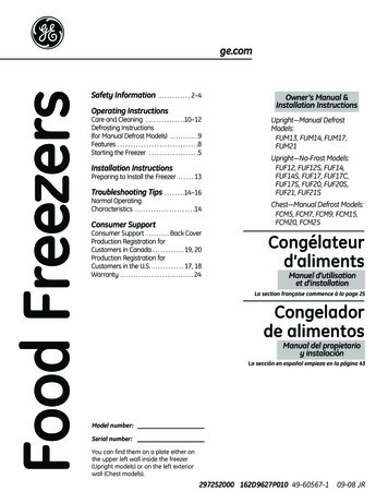
TRUEwww.truemfg.comtfmWIRE GAUGE CHART115 VoltsAmps23456Distance In Feet To Center of Load20 30 40 50 60 70 80 90 100 120 140 888668666666665665546554465443544334433243221230 VoltsAmps56789Distance In Feet To Center of Load20 30 40 50 60 70 80 90 100 120 140 2211KEYSNOTE: Keys for coolers with door locks are located in warrantypackets.A. Insert key with lock into the key hole. Turn and pull the key out.The lock will stay in the key hole.B.To remove the lock from the key hole simply do the reverseprocess. Insert the key into the lock. Turn and pull the key andlock out of the key hole. See images 1-3.1234
TRUEwww.truemfg.comtfmLOCATINGLEVELINGA. Place packing material behind cabinet as a cushion. Carefully laythe unit on its back to remove skid.A. Set unit in its final location. Be sure there is adequate ventilationin your room. Under extreme heat conditions, (100 F ,38 C ), you may want to install an exhaust fan.WHEN LIFTING UNIT REMEMBER TO LEAVETHE CABINET UPRIGHT FOR 24 HOURS BEFOREPLUGGING INTO POWER SOURCE.B.Remove skid by unscrewing all base rail anchor brackets. Placeskid to the side. (See image 1)WARNING: WARRANTY IS VOID IF VENTILATION ISINSUFFICIENT.B.C. Carefully lift cabinet upright.Proper leveling of your TRUE cooler is critical to operatingsuccess (for non-mobile models). Effective condensate removaland door operation will be effected by leveling.D. Applicance tested according to the climate classes 5 and 7 fortemperature and relative humidity.C. The cooler should be leveled front to back and side to side witha level.RECOMMENDED OPERATION CONDITIONS(75 F DEGREES & 55% RELATIVE HUMIDITY)D. Ensure that the drain hose or hoses are positioned in the pan.E.Free plug and cord from inside the lower rear of the cooler(do not plug in).F.The unit should be placed close enough to the electrical supplyso that extension cords are never used.WARNING: CABINET WARRANTIES ARE VOIDIF OEM POWER CORD IS TAMPERED WITH. TRUEWILL NOT WARRANTY ANY UNITS THAT ARECONNECTED TO AN EXTENSION CORD.1Removing skid from bottom of cabinet.VENTILATIONSet unit in its final location. Be sure there is adequate ventilation inyour room. Maximum ambient operating temperature is 75 F / 55%humidity.WARNING: WARRANTY IS VOID IF VENTILATION ISINSUFFICIENT. CABINET DRAINTRUE Freezer Merchandiser Cabinets have a drain at the bottom ofthe unit. (See image 1). When cleaning the unit make sure the drainhose is connected to a hose that is routed to a floor drain.CabinetDrain15Exterior CabinetDrain2
TRUEwww.truemfg.comtfmINSTALLATION OF CASTORS OROPTIONAL LEGSSEALING CABINET TO FLOORSTEP 1 - Position Cabinet - When positioning cabinet into a finallocation make sure there are no obstructions in front of the intakeand exhaust areas. These areas are located in the front and back ofthe cabinet.Important Safeguard for installation of leg/castor.SECURING CASTORSTo obtain maximum strength and stability of the unit, it is importantthat you make sure each castor is secure. The bearing race on thecastor or the top edge of the leg must make firm contact with the rail.LEVELING SHIMSFour leveling shims have been provided for leveling castored unitspositioned on uneven floors. Shims must be positioned between railend and bearing race.A. Turn the bearing race counter-clockwise until the cabinet islevel. Level front to back and side to side. (diagonally)B.Install the desired number of shims, making sure the slot of theshim is in contact with the threaded stem of the castor. Seeimage 2.C. If more than one shim is used, turn the slot at a 90 angle sothey are not in line.D. Turn the bearing race clockwise to tighten and secure thecastor by tightening the anchoring bolt with a 3/4 inch openend wrench or the tool provided. See image 1.STEP 2 - Level Cabinet - Cabinet should be level, side to side andfront to back. Place a carpenter’s level in the interior floor in fourplaces:A. Position level in the inside floor of the unit near the doors.(Level should be parallel to cabinet front). Level cabinet.B.Position level at the inside rear of cabinet. (Again level shouldbe placed parallel to cabinet back).C. Perform similar procedures to steps A & B by placing the levelon inside floor (left and right sides - parallel to the depth of thecooler). Level cabinet.STEP 3 - Draw an outline on the base on the floor.STEP 4 - Raise and block the front side of the cabinet.STEP 5 - Apply a bead of “NSF Approved Sealant”, (see list below),to floor on half inch inside the outline drawn. The bead must be heavyenough to seal the entire cabinet surface when it is down on thesealant.STEP 6 - Raise and block the rear of the cabinetSTEP 7 - Apply sealant on floor as outlined in Step 5 on otherthree sides.CAUTION: TO AVOID DAMAGE TO LOWER RAILASSEMBLY, SLOWLY RAISE UNIT TO UPRIGHTPOSITION.STEP 8 - Examine to see that cabinet is sealed to floor aroundentire perimeter.NOTE: OPEN HOLES LOCATED ON THE CROSSMEMBERS OF THE FRAME RAIL SHOULD BEPLUGGED BEFORE UNIT IS IN USE.NOTE: Asphalt floors are very susceptible to chemical attack. Alayer of tape on the floor prior to applying the sealant will protectthe floor.NSF APPROVED SEALANTS:1. Minnesota Mining #ECU800 Caulk2. Minnesota Mining #ECU2185 Caulk3. Minnesota Mining #ECU1055 Bead4. Minnesota Mining #ECU1202 Bead5. Armstrong Cork - Rubber Caulk126. Products Research Co. #5000 Rubber Caulk7. G.E. Silicone SealerLower RailAssemblyLower Rail Assembly8. Dow Corning Silicone SealerRail EndSnug FitHereRail EndBearingRaceSnug FitHereLeveling ShimLegCastor6
TRUEtfmwww.truemfg.comOPERATIONSTARTUPA. The compressor is ready to operate. Plug in the cooler.B.Temperature controls are factory-set to give freezers anapproxiate temperature of -10 F. Allow unit to function severalhours, completely cooling cabinet before changing the controlsetting.Temperature Control Location and Settings. M echanical temperature control is located on rear of unit orbehind access grill.See website for adjustments, sequence of operation, and moreinformation.C. Excessive tampering with the control could lead to servicedifficulties. Should it ever become necessary to replacetemperature control, be sure it is ordered from your TRUEdealer or recommended service agent.7D. Good air flow in your TRUE unit is critical. Be careful toload product so that it neither presses against the back wall,nor comes within four inches of the evaporator housing.Refrigerated air off the coil must circulate down the back wall.NOTE: If the unit is disconnected or shut off, wait five minutesbefore starting again.RECOMMENDATION - Before loading product we recommendyou run your TRUE unit empty for two to three days. This allowsyou to be sure electrical wiring and installation are correct and noshipping damage has occurred. Remember, our factory warranty doesnot cover product loss!
TRUEwww.truemfg.comtfmMECHANICAL TEMPERATURE CONTROLSCOIL SENSINGAn evaporator coil sensing temperature control ensures that the evaporator coil will remain clearof frost and ice by not allowing the compressor to restart until the coil temperature is above thefreezing temperature. This is considered an off cycle defrost.MECHANICAL TEMPERATURE CONTROL GENERAL SEQUENCE OF OPERATIONMECHANICAL CONTROL TFM GENERAL SEQUENCE OF OPERATION1.Cabinet is plugged in.2.The compressor only will start if the temperature control is calling for cooling. (If the compressor does not start, verify thatthe temperature control is not in the “OFF” or “0” position.3.The temperature control will cycle the compressor on and off.a.The temperature control is sensing the air temperature.b.The temperature control should be set on the #4 or #5.c.The warmest setting is #1, the coldest is #9, and #0 is the off position.d. The thermometer is designed to read and display a cabinet temperature not a product temperature.The thermometer may reflect the refrigeration cycle swings of up and down temperatures.The most accurate temperature on a cabinet's operation is to verify the product temperature.4.The control will not initiate defrost.a. The cabinet will need to be manually defrosted. The manual defrost frequency will depend on the unit's usage,environment and the amount of frost.8
TRUEwww.truemfg.comtfmWHEN TO MAKE AN ADJUSTMENT TO A MECHANICAL TEMPERATURE CONTROLWe advise to make a mechanical temperature control adjustment only for a high altitude location.HOW TO ADJUST A MECHANICAL TEMPERATURE CONTROLOPERATION INSTRUCTIONS:Scale Guide for MeasuringREQUIRED TOOLS: Jewelers Screw Driver (Small Screw Driver)50GE CONTROL INSTRUCTIONS:510RME RWA45The scale to the right may be used as a guide for measuringdegrees of rotation required for altitude correction. See Figure 1.The arrows indicate direction of screw rotation. Turn calibrationscrew clockwise to obtain warmer operating temperatures.NOTE: Each 1/4 turn of the calibration screw is equal toapproximately 2 degrees F. Do not make more than 3/4 turn.After making adjustment, measure temperature during threecycles before adjusting again.NOTE: Only adjust the screw(small flathead) on the face ofthe control (next to the cam).See Figure 3.Follow the Altitude CorrectionTable to the right.CO40LD E R351202530Altitude CorrectionAltitude ise Turns7/6011/6015/6019/6023/6027/6030/6034/6037/60 Torx Screw (T-7)2Front of Temperature ControlCalibrationScrewTo adjust the temperature controltake the control knob off to view thecut-in screw. (See Photo Above)3Bottom of Temperature ControlCut-out AdjustmentScrew Allen (5/64" or 2 mm.)REQUIRED TOOLS:Allen Wrench (5/64")GroundTerminal15ALTITUDE CORRECTION TABLE:CALIBRATION SCREW ADJUSTSBOTH CUT-IN AND CUT-OUTINSTALLATION INSTRUCTIONSDANFOSS TEMPERATURE CONTROL ADJUSTMENTFOR HIGH ALTITUDE APPLICATIONS: CompressorTerminals6055Back of Temperature ControlCut-in AdjustmentScrew Torx (T-7)TERMS:Cut-out - Temperature sensed by the controller that shuts thecompressor off.Cut-in - Temperature sensed by the controller that turns thecompressor on.91CompressorConnectionCompressor Connection(double terminal)
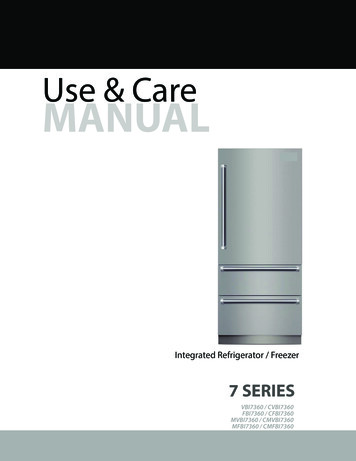
TRUEwww.truemfg.comtfmINSTRUCTIONS: DANFOSS TEMPERATURE CONTROL ADJUSTMENT FORHIGH ALTITUDE APPLICATIONSSTEP 1 - Unplug cooler.STEP 2 - Remove the screws that secure the temperature control to the inset box.STEP 3 - To make these adjustments it may be necessary to remove the temperature control from the housing.NOTE: You may have to remove the wires attached to the control. Take note as to which wire is on which spade terminal.STEP 4 - Pull out gently from cabinet.NOTE: Mechanical temperature controllers are affected when functioning at high altitude.The cut-in and cut-out temperatures will be colder than when the controller functions closer to sea level.STEP 5 - For high elevation installations, it may be necessary to “warm-up” the set points. To make the adjustment, insert theappropriate tool in each adjustment screw and turn 1/4 of a revolution clockwise (to the right). This procedure will adjust boththe cut-in and cut-out about 2 F warmer.STEP 6 - Make sure to reconnect the wires to the proper spade terminal when reinstalling.INSTALLATION INSTRUCTIONSTEMPERATURE CONTROL ALTITUDE ADJUSTMENT:Scale Guide for MeasuringREQUIRED TOOLS: Allen Wrench (5/64”) Torx Screw (T-7)36090The scale to the right may be used as a guide for measuring degrees of rotation required for altitudecorrection. The arrows indicate direction of screw rotation. See Figure 1.IMPORTANT: Upright models ordered with “High Altitude” temperature controls arepre-calibrated and do not require adjustment.2701801INSTRUCTIONS: CUTLER HAMMER TEMPERATURE CONTROL ALTITUDE ADJUSTMENTSTEP 1 - Unplug cooler.STEP 2 - Turn the temperature control to the “9” position.STEP 3 - Remove the screws that secure the mounting plate to the evaporator top. See Figure 2.STEP 4 - Pull control down gently from housing.STEP 5 - Turn screws counterclockwise (CCW).STEP 6 - Reassemble to cooler housing and return the temperature control to the “5” position.10
NO8111927BUL. NO.2842 78 114 150 186 222 258 294 330 5OHeightCCW Adjustment(based on 360 /complete turn)
TRUEwww.truemfg.comtfmDEFROST OPERATIONSMANUAL DEFROST:IF ICE BUILDS UP ON INTERIOR WALLS-The unit will need to be manually defrosted. Unplug unit until all frostis gone. The manual defrost frequency will depend on the units usage,environment, and the amount of frost.A. Remove product, unplug and roll unit so defrost plug is abovefloor drain (or large flat pan).B.NOTERemember to place the unit close to a floor drain when manuallydefrosting unit. Make sure the drain plug is removed when manuallydefrosting the unit.Remove plug and allow ice to melt and drain. Do not scrapeinterior of cabinet to loosen ice, as this will damage the cabinet.Allow cabinet to defrost with power off.C. When ice has melted wipe up and water left in the freezerfloor.D. Be sure to replace defrost plug before moving freezer back inposition.E.Allow freezer to refrigerate and cycle before placing wirebaskets and product back into freezer.12
TRUEwww.truemfg.comtfmMAINTENANCE, CARE, CLEANINGCLEANING THE CONDENSER COILWhen using electrical appliances, basic safety precautions should befollowed, including the following:TOOLS REQUIRED Phillips Screwdriver Air Tank or CO2 Tank Stiff Bristle Brush Vacuum Cleaner Adjustable Wrench STEP 1Disconnect power to unit. Take off lower grill assembly. Removephillips screws at the bottom of the grill. Holding grill at the bottomgently pull out and down as shown. (see illustration 1).STEP 2Clean off accumulated dirt from condensing coil with a stiff bristlebrush and clean fan bladeIllustration 1NOTE: It may be necessary to use CO2 or compressed air to blowoff any dust or debris from condenser coil. Use a vacuum to cleanup any debris.WARNING: Do not bend or disrupt the refrigeration lines whencleaning the condenser coil.TRUE is not responsible for damage doneto the condensing unit and refrigeration lines.STEP 3Remove bolts anchoring compressor assembly to frame rails andcarefully slide out. (tube connections are flexible) STEP 4Lift W.R. Board cover above fan at plastic plugs and carefully cleancondenser coil and fan blade.STEP 5After brushing condenser coil vacuum dirt from coil, and interiorfloorSTEP 6Carefully slide compressor assembly back into position and replacebolts.STEP 7Reinstall grill assembly onto unit. Connect unit to power and checkto see if fan blade is turning.13Illustration 2
TRUEwww.truemfg.comtfmIMPORTANT WARRANTY INFORMATIONCondensers accumulate dirt and require cleaning every 30 days.Dirty condensers result in compressor failure, product loss, and lostsales, which are not covered by warranty.If you keep the Condenser clean you will minimize your serviceexpense and lower your electrical costs. The Condenser requiresscheduled cleaning every thirty days or as needed.Air is pulled through the Condenser continuously, along with dust,lint, grease, etc.A dirty Condenser can result in NON-WARRANTEED part &Compressor Failures, Product Loss, and Lost Sales.Proper cleaning involves removing dust from the Condenser. By usinga soft brush, or vacuuming the Condenser with a shop vac, or usingCO2, nitrogen, or pressurized air.If you cannot remove the dirt adequately, please call your refrigeration service company.On most of the reach-in units the condenser is accessible in therear of the unit. You must remove the cabinet grill to expose theCondenser.The Condenser looks like a group of vertical fins. You need to be ableto see through the condenser for the unit to function at maximumcapacity. Do not place filter material in front of condensing coil. Thismaterial blocks air-flow to the coil similar to having a dirty coil.THE CLEANING OF THE CONDENSER IS NOTCOVERED BY THE WARRANTY!HOW TO CLEAN THE CONDENSER:1.Disconnect the electrical power to the unit.2.Remove the louvered grill.3.Vacuum or brush the dirt, lint, or debris from the finnedcondenser coil.4.If you have a significant dirt build up you can blow out thecondenser with compressed air.(CAUTION MUST BE USED TO AVOID EYE INJURY.EYE PROTECTION IS RECOMMENDED.)5.When finished be sure to replace the louvered grill. The grillprotects the condenser.6.Reconnect the electrical power to the unit.If you have any questions, please call TRUE Manufacturing at 636-2402400 or 800-325-6152 and ask for the Service Department. Directto Service Department 1(855)372-1368. Service DepartmentAvailability Monday-Thursday 7:00 a.m. to 7:00 p.m., Friday 7:00 a.m.to 6:00 p.m. and Saturday 8:00 a.m. to 12:00 p.m. CST.AirflowCondensing UnitCondenser14
TRUEwww.truemfg.comtfmSTAINLESS STEEL EQUIPMENT CAREAND CLEANING8 STEPS THAT CAN HELP PREVENT RUST ONSTAINLESS STEEL:CAUTION: Do not use any steel wool, abrasive or chlorine basedproducts to clean stainless steel surfaces.1.USING THE CORRECT CLEANING TOOLSUse non-abrasive tools when cleaning your stainless steelproducts. The stainless steel’s passive layer will not be harmedby soft cloths and plastic scouring pads. Step 2 tells you how tofind the polishing marks.2.CLEANING ALONG THE POLISH LINESPolishing lines or “grain” are visible on some stainless steels.Always scrub parallel to visible lines on some stainless steels.Use a plastic scouring pad or soft cloth when you cannot seethe grain.3.USE ALKALINE, ALKALINE CHLORINATED ORNON-CHLORIDE CONTAINING CLEANERSWhile many traditional cleaners are loaded with chlorides, theindustry is providing an ever increasing choice of non-chloridecleaners. If you are not sure of your cleaner’s chloride contentcontact your cleaner supplier. If they tell you that your presentcleaner contains chlorides, ask if they have an alternative. Avoidcleaners containing quaternary salts as they can attack stainlesssteel, causing pitting and rusting.4.WATER TREATMENTTo reduce deposits, soften the hard water when possible.Installation of certain filters can remove corrosive and distastefulelements. Salts in a properly maintained water softener can beto your advantage. Contact a treatment specialist if you are notsure of the proper water treatment.5.MAINTAINING THE CLEANLINESS OF YOURFOOD EQUIPMENTUse cleaners at the recommended strength (alkaline chlorinatedor non-chloride). Avoid build-up of hard stains by cleaningfrequently. When boiling water with your stainless steelequipment, the single most likely cause of damage is chlorides inthe water. Heating any cleaners containing chlorides will havethe same damaging effects.6.RINSEWhen using chlorinated cleaners you must rinse and wipe dryimmediately. It is better to wipe standing cleaning agents andwater as soon as possible. Allow the stainless steel equipmentto air dry. Oxygen helps maintain the passivity film on stainlesssteel.7.HYDROCHLORIC ACID (MURIATIC ACID)SHOULD NEVER BE USED ON STAINLESS STEEL8.REGULARLY RESTORE/PASSIVATE STAINLESSSTEELSTAINLESS STEEL OPPONENTSThere are three basic things which can break down your stainlesssteel’s passivity layer and allow corrosion to rear its ugly head.1.Scratches from wire brushes, scrapers,
Parts Department (800)-424-TRUE Parts Department FAX# (636)-272-9471 Web: www.truemfg.com CONGRATULATIONS! You have just purchased the finest commercial refrigerator available. You can expect many years of trouble-free operation. TRUE food service equipment, inc. INSTALLATION MANUAL INSTALLATION MANUAL tfm - true freezer merchandiser .