Transcription
VHF/UHF FMAIRBORNE TRANSCEIVERMODEL TFM-500(P/N’s 971083-1,3 -VHF Guard Module)Installation andOperating InstructionsTil Document No.98RE243Rev. N/CIssue 7August 2002Technisonic Industries Limited240 Traders Boulevard, Mississauga, Ontario L4Z 1W7Tel:(905)890-2113 Fax:(905)890-5338www.til.ca
CAUTIONThis unit contains static sensitive devices. Wear a grounded wrist strap and/or conductive gloves whenhandling printed circuit boards.NOTE: This equipment has been tested and found to comply with the limits fora Class A digital device, pursuant to Part 15 of the FCC Rules. These limits aredesigned to provide reasonable protection against harmful interference whenthe equipment is operated in a commercial environment. This equipmentgenerates, uses, and can radiate radio frequency energy and, if not installedand used in accordance with the instruction manual, may cause harmfulinterference to radio communcations. Operation of this equipment in aresidential area is likely to cause harmful interference in which case the userwill be required to correct the interference at his own expense.Warning:Changes or modifications not expressly approved by Technisonic Industries could voidthe user’s authority to operate the equipment.WARRANTY INFORMATIONThe Model TFM-500, Transceiver is under warranty for one year from date of purchase. Failed unitscaused by defective parts, or workmanship should be returned to:Technisonic Industries Limited240 Traders BoulevardMississauga,Ontario L4Z 1W7Tel: (905) 890-2113Fax: (905) 890-5338A Page
Summary ofTransceiver:DO-160C Environmental Testing for Technisonic Model TFM-500,VHF and UHFConditionsSectionDescription of Conducted TestsTemperature and Altitude4.0Equipment tested to categories B2 andD1.Vibration8.0Equipment is tested without shockmounts to categories B, M and N.Magnetic Effect15.0Equipment is class A.Power Input16.0Equipment tested to category B.Voltage Spike17.0Equipment tested to category B.RF Emission21.0Equipment tested to category Z.Installation Approval NotePresently no TSO standard exists for airborne FM transceivers. To make it easier for installationagencies to provide their customers with an approved installation supported by an effectiveAirworthiness Approval, Technisonic has secured Supplemental Type Certificate (STC) Approvals (bothUS and Canadian) on its Airborne FM products for many helicopters currently being delivered in theUS and Canada as well as a number of single engine fixed wing aircraft. The above referenced DO160C test data is also on file and available from Technisonic to support approval requirements inairframes for which Technisonic does not possess an STC.Approved aircraft types are listed in the attachments to the formal STC documents. These STC's arethe exclusive property of Technisonic and require the written authority of Technisonic for their use.To assist Factory Authorized Technisonic Dealers in the certification process, we have placed copiesof our Canadian and US STC's on our web site along with a letter of authorization for their use. Thesedocuments may be downloaded and used as support for the technical submission to FAA or TransportCanada. Only factory authorized dealers/installers are permitted to download and make use of thesedocuments on behalf of their customers (end users) in support of regulatory agency approval. Pleaserefer to the Technisonic web site www.til.ca for the latest issue of available STC’s and letter ofauthorization for use.B page
TABLE OF CONTENTSTitleParagraphSECTION 11.11.21.31.41.5SECTION CTION .63.7.73.7.83.7.93.83.93.103.113.123.13PageGENERAL DESCRIPTIONIntroduction . . . . . . .Description . . . . . . .Purpose of EquipmentModel Variation . . . .Technical Summary . .1-11-11-11-11-2Features . . . . . . . . . . . . . . . . . . . . . . . . . . . .Operating Instructions . . . . . . . . . . . . . . . . . . .Programming Instructions . . . . . . . . . . . . . . . .Priority and Selective Memory Channel ScanningScanning Function . . . . . . . . . . . . . . . . . . . . .Direct Frequency Entry Mode . . . . . . . . . . . . . .Receive Frequency Simplex Function . . . . . . . . .Keyboard Lockout Function . . . . . . . . . . . . . . .Variable Frequency Mode Function . . . . . . . . . .LED Display Variable Dimming Mode . . . . . . . . .90 Second Transmitter Time Out Feature . . . . .Quick Guard Programming Feature . . . . . . . . . .Programming CTCSS Tones . . . . . . . . . . . . . . .PC Memory/Programming Download Capability . .2-12-32-42-42-52-52-52-62-62-62-62-62-72-8General . . . . . . . . . . . . . . . . . . . . . . . . . . . . . . . . . .Equipment Packing Log . . . . . . . . . . . . . . . . . . . . . . .Transceiver Installation . . . . . . . . . . . . . . . . . . . . . . .Installation Kit - Contents . . . . . . . . . . . . . . . . . . . . .Antenna Installation . . . . . . . . . . . . . . . . . . . . . . . . .Installation - Pin Locations and Connections . . . . . . . . .Wiring Instructions . . . . . . . . . . . . . . . . . . . . . . . . . .Main Power 28VDC . . . . . . . . . . . . . . . . . . . . . . . .Main Ground . . . . . . . . . . . . . . . . . . . . . . . . . . . . . .PTT (Ground Keying) . . . . . . . . . . . . . . . . . . . . . . . . .Front Panel Back Lighting . . . . . . . . . . . . . . . . . . . . .Audio Outputs (600 and 4 Ohms) . . . . . . . . . . . . . . . .Audio Output Ground . . . . . . . . . . . . . . . . . . . . . . . .Mic Signal Input . . . . . . . . . . . . . . . . . . . . . . . . . . . .Memory Up/Memory Down . . . . . . . . . . . . . . . . . . . .Data Input . . . . . . . . . . . . . . . . . . . . . . . . . . . . . . . .Internal Programming and Guard Enable/Disable JumperTransmitter Power Adjustments . . . . . . . . . . . . . . . . .Transmitter Microphone Level Adjustment . . . . . . . . . .Main and Guard Squelch Adjustment . . . . . . . . . . . . . .Transmitter Deviation Adjustment . . . . . . . . . . . . . . . .Guard Receiver Audio Limit Feature . . . . . . . . . . . . . -53-73-73-93-93-9OPERATING INSTRUCTIONSINSTALLATION INSTRUCTIONSi
LIST OF TABLESTable No.3-1TitlePage9-pin D and 15-Pin D Connections . . . . . . . . . . . . . . . . . . . . . . . . . . . . . . . 3-3LIST OF ILLUSTRATIONSFigure No.2-12-23-13-23-33-43-53-6TitleOperator's Switches and Controls . . . . . . . . . . . .PC Up/Download Cable - Wiring Diagram . . . . . . .Outline Drawing . . . . . . . . . . . . . . . . . . . . . . . .Wiring Connections . . . . . . . . . . . . . . . . . . . . . .Interal Enable/Disable Jumper Locations . . . . . . .External Adjustment Access Holes . . . . . . . . . . .VHF Deviation Adjustment Potentiometer LocationUHF Deviation Adjustment Potentiometer LocationiiPage. 2-32-12. 3-2. 3-4. 3-7. 3-83-103-10
SECTION 1GENERAL DESCRIPTION1.1INTRODUCTIONThis publication provides operating and installation information on the TFM-500 Transceiver.manufactured by Technisonic Industries Limited. The unit offers an extended frequency rangewith selectable channel spacing and is intended for use (in the U.S.) only by governmentagencies or contractors thereto, who have obtained licensing for operation in the 138-150 MHzportion of the band. If the TFM-500 transceiver is used in CANADA, VHF operation isrestricted to the following sub bands: 138-144, 148-148.99, 149.005-150.005 and 150.05174 MHz.1.2DESCRIPTIONThe TFM-500, Transceiver is a frequency agile, fully synthesized airborne transceivercapable of operating in the 138 to 174 MHz and 403 to 512 MHz frequency range in 2.5 kHzincrements with either 25 kHz or 12.5 kHz channel spacing. The Transceiver can operatewithout restriction on any split frequency pair in either band and also incorporates a twochannel VHF synthesized guard receiver.The TFM-500 Transceiver provides 200 operator accessible memory positions per band, eachof which is capable of storing a transmit frequency, receive frequency, transmit frequencyCTCSS tone or DPL code, receive frequency CTCSS tone or DPL code, an alphanumericidentifier for each channel and wideband (25 kHz) or narrowband (12.5 kHz) channel spacingassignment. Operating frequency and other related data are presented on a 96 character, fourline LED matrix display. Data entry and function control are performed via a 12 button keypad.Preset channels may also be scrolled and scanned through keypad function activation. Datamay also be entered via a Windows 95/98/NT/2000/ME based computer with the providedsoftware and optional PC Up/download cable, P/N 993390-1.1.3PURPOSE OF EQUIPMENTThe TFM-500, VHF/UHF FM Transceiver is designed to provide secondary airbornecommunications to facilitate operations which are typically performed in a low altitudeenvironment. The transmitter sections of this unit have a minimum of 8 watts and do notexceed 10 watts output power, which may be reduced by a front panel switch to 1 watt, inorder to reduce interference to land based systems.1.4MODEL VARIATIONThere are four variations of the Model TFM-500 Transceiver. All units offer identical featuresand performance except for the following differences:TFM-500, P/N 971083-1GREEN display and 28 Volt back lighting.TFM-500, P/N 971083-1 (5V),GREEN display and 5 Volt back lighting.TFM-500, P/N 971083-3RED display and 28 Volt back ligting.TFM-500, P/N 971083-3 (5V),RED display and 5 Volt back lighting.Both P/N's 971083-1 and 971083-3 are always provided with 28 Volt back lighting unless aspecific request is made for 5 Volt AC operation.1-1
1.5TECHNICAL odel Designation:TFM-500Frequency Range:138 to 174 and 403 to 512 MHzTuning Increments:2.5 kHzOperating Mode:F3E simplex or semi-duplexChannel Spacing:25 or 12.5 kHzPhysical Dimensions (including heatsink):Weight:Approx. 8.0" X 3.0" X 5.75"Approx. 5.1 Lbs (2.3 Kg)Mounting:Panel Mount via Dzus fastnersOperating Temperature Range:-40EC to 60ECPower Requirement:Voltage:Current:28.0 Vdc, 15%Receive - 1.0 A Max.1 Watt Transmit - 2.0 A Max.8-10 Watt Transmit - 3.2 A Max.8-10 Watt Dual Trans - 5 A Max.Frequency Selection:200 memories per bandprogrammed with:a) Tx Frequency/Rx Frequencyb) Tx/Rx CTCSS tone or DPL codec) 9 character alpha numeric titleGuard Receiver:2 channels programmed with:a) Tx Frequency/Rx Frequencyb) Tx CTCSS tone or DPL codec) 9 character alpha numeric titleCTCSS squelch/encoder:All CTCSS tones availableDPL digital squelch/encoder:All standard DPL codesDTMF encoder:Audio Outputs:All standard DTMF tones0.5 Watts into 600 ohmsSpeaker Output:2.5 Watts min. into 4 ohmsBack Lighting:28 Volts (standard) or5 Volts (specify)Display Colour:Green (standard) or Red (specify)DPL is a trademark of Motorola Corporation1-2
1.5TECHNICAL CHARACTERISTICS (continued)VHF RECEIVERSensitivity at 12 dB SINADBetter than 0.35 µVAdjacent Channel Selectivity-75 dB (25 kHz)-70 dB (12.5 kHz)Spurious Attenuation-90 dBThird Order Intermodulation-70 dBImage Attenuation-80 dBFM Acceptance 6 kHzHum and NoiseBetter than 45 dBAudio Distortionless than 5%Antenna Conducted Emissionless than -70 dBmUHF RECEIVERSensitivity at 12 dB SINADBetter than 0.35 µVAdjacent Channel Selectivity-70 dB (25 kHz)-60 dB (12.5 kHz)Spurious Attenuation-80 dBThird Order Intermodulation-70 dBImage Attenuation-60 dBFM Acceptance 6 kHzHum and NoiseBetter than 40 dBAudio Distortionless than 5%Antenna Conducted Emissionless than -70 dBmGUARD RECEIVERAll specifications identical to VHF receiver1-3
VHF and UHF TRANSMITTERRF Power Output1 watt or 10 wattsOutput Impedance50 ohmsMaximum Deviation(In narrowband mode) 5 kHz (25 kHz mode) 2.5 kHz(12.5kHz mode)Spurious Attenuation-90 dB below carrier levelFrequency Stability 2.5 ppmMicrophone CircuitCarbon or equivalentSidetone Output0.5W (max) into 600SHarmonic Attenuation-65 dB below carrier levelFM Hum And Noise-40 dBAudio Input50 mV at 2.5 kHz into200 S input circuit for 3.5kHz deviation, adjst.Audio DistortionLess than 5%1-4
SECTION 2OPERATING INSTRUCTIONS2.1FEATURESThe equipment has several important operating features which provide maximum flexibility,performance and versatility. These features include:1. VHF and UHF bands that can be configured to be operated independently or as a singleunit.2. The unit can be set up as a crossband repeater, linking a VHF and UHF frequency in bothdirections.3. 200 memory positions per band which can each be programmed with a transmit andreceive frequency with 25 or 12.5 kHz channel spacing, Tx/Rx CTCSS tones or DPL codesand a 9-character alphanumeric title.4. 2 guard channels which can each be programmed with a Rx frequency with 25 or 12.5kHz channel spacing, CTCSS Tx tone or DPL code and a 9-character alphanumeric title.5. Scanning of preprogrammed memories with selective memory scanning, in 5 scan lists.6. Priority scan of memory channel 1, if desired.7. Direct frequency entry mode.8. Receive frequency simplex function.9. Switchable RF output power between 1 watt and 8-10 watts.10. Lockout of keyboard to prevent inadvertent entries.11. Variable frequency mode to manually scan up and down in 2.5 kHz steps.12. LED display variable dimming mode.13. Selectable 90 second Tx time out feature.14. Quick download of any of the VHF memory positions to the guard memories.15. PC Memory Upload or Download capability.16. Configuration Menu - Pressing ENTER, RCL and FUNC together while turning the radioon will put it into configuration mode.The programming featuresaffected are:a) DPL - Can be turned on or off with th MUP and MDN (4 and 7) keys. This onlyremoves the DPL entry step from the programming sequence and does notstop memories that already have DPL codes from working. This also applies tothe rest of the on/off configurable items.b) Scan - Can be disabled. Selecting FUNC and SCAN will do nothing if Scan is off. Thescan list indicator ( ) will still display if was previously programmed.c) Rx CTCSS - Can be turned on or off from the programming sequence. This affects onlythe CTCSS tones for receive.d) FUNC 7 - Can be turned on or off. When off, the main memory channel can not bedumped into one of the guard channels using function 7.e) LAST MEM - If set to on, the last memory channel on the display will be what comesup when the radio is turned on. If set to off, the last memory that changeswere made to will be what comes up when the unit is switched on.f) DUALMODE - If set to on, the UHF and VHF bands are operated independently andsimultaneously. The radio is shipped with this feature OFF.2-1
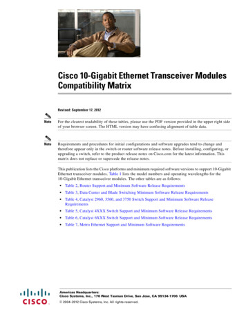
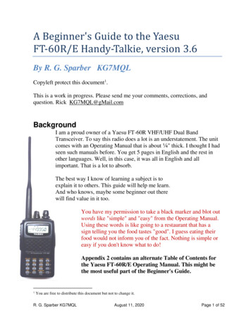
g) SIDETONE - The TX audio circuit becomes active allowing you to adjust the sidetonelevel with the VHF volume knob. When thedesired level is reached, pressENTER and this level will be set for both VHF and UHF bands. The factorysetting is 23.Note: You must set the side tone every time you go through the configurationmenu since the position of the knob is taken as the new level regardless ofwhether or not you made an adjustment.FIGURE 2-1Operator's Switches and Controls2-2
2.2OPERATING INSTRUCTIONS (See Figure 2-1)1. Switch power on by turning the main volume clockwise. Depending how the radio isconfigured, either the last programmed or last displayed frequencies will appear on thescreen. The transceiver is now in normal operating mode.2. Adjust the audio level by adjusting the VHF, UHF and GUARD volume knobs.3. Pressing the squelch defeat button will open all receivers to confirm they work.4. Read the display. The top line will indicate which VHF memory is selected followed by a" " if the memory position is included in a scan list, an alphanumeric message, and thefrequency of the VHF receiver. A small "n" before the frequency indicates 12.5 kHznarrowband channel spacing is in effect on this memory position. In the receive mode, thefrequency is followed by an "RT" if a RX CTCSS tone or RX DPL code is programmed, oran "RX" if no Receive tone/code is programmed. Similarily, in the transmit mode either a"TT" or "TX" is shown after the frequency. The second line shows the same informationfor the UHF band. The third line indicates information about the guard receiver.5. Only TX CTCSS tones or TX DPL codes may be programmed for the guard receiver.At the beginning of each line, an LED indicates open squelch.6. Set the VHF/UHF/GD switch to the desired band.7. Set the G1/G2 switch to the desired guard channel.8. Set the HI/LO switch to the desired RF output power.9. Select the desired memory by using the M.UP and M.DN buttons, or the RCL buttonand a three digit number followed by ENTER.10. To transmit DTMF tones, use the keyboard keys while holding the PTT button on themicrophone. There is a 5 second PTT delay after pressing a key so that you may pressseveral DTMF keys in sequence without having to hold the PTT. The keyboard returns toits normal function when the PTT is released.The display always shows the status of both receivers and the transmitter. The light at the leftof each line indicates which receiver is receiving. The display also indicates the memorychannel in use and the guard channel in use. A "TX" (no TX tone/codes programmed) or"TT"(either TX tone or code programmed) on the right side of the display indicates which bandis active when transmitting. The transmit frequency is also shown. In the receive mode thedisplay shows “RX” beside the receive frequency if no RX tone or DPL code is programmedand “RT” if a CTCSS tone or DPL code is programmed.While in any programming mode, all receivers continue to function.When the transceiver is in either of the operating frequency or CTCSS tone/DPL codeprogramming modes and you must respond to a call, click the microphone PTT once (the radiowill not transmit during this click). This will cause the transceiver to revert back to the normaloperating mode and communications with the caller can proceed in the usual fashion.2.3PROGRAMMING INSTRUCTIONSTo program one of the 200 memory channels in one of the bands:1. Select the desired band on the band select (VHF/UHF/GD) switch. This is required beforeany of the programming modes or functions.2-3
2. Press the FUNC key. The display will show the function prompt.3. Press the PROG key. The display will show the current receive frequency with a flashingcurser on the first or second digit (The first digit is always a one 1 on the VHF band).4. Type in the desired receive frequency. If you type in a frequency which is not a 2.5 kHzstep, the nearest valid frequency will be automatically selected.5. The curser will return to the second digit. You can retype the frequency if youhave made an error or press ENTER to continue.6. The transmit frequency will be displayed with the curser on the seconddigit. Follow the same method as in step 3 and 4.7. The channel spacing increment of either 25.0 or 12.5 kHz is now displayed. Use theM.UP and M.DN keys to select the desired channel spacing for the memory position,then press ENTER.8. The alpha-numeric title is now displayed. Use the M.UP and M.DN keys to scrollthrough the alphabet, numbers and symbols. When the desired character is displayed,press ENTER to advance to the next character. Press “1" to backspace.9. Keep repeating step six until the last space is set. The display will show SCAN orLOCKOUT to enable this memory position as part of a scan list or lock it out of thescan list. Use the 1,2,3,4,5 and M.DN keys to toggle between these functions (fordetails see paragraph 2.5). Once the desired condition has been selected, press ENTER.The TFM-500’s display will show a " " beside the memory channel number if scanis enabled.10. The display will now show the current memory number. Type in the 3-digit number ofthe memory you want to save to (if different from displayed one) and press ENTER.11. You now have the option to program the guard frequencies by pressing FUNC or pressENTER to return to normal operating mode.12. If you pressed FUNC to program the guards, guard"1" transmit frequency will bedisplayed with the flashing curser on the second digit. Enter the frequencies forguard"1" receive/transmit and guard"2" receive/transmit as in step 3 and 4.13. The alphanumeric labels for guard"1" and guard"2" are entered the same as in step 7and 8. When the last character is entered, the radio returns to normal operating mode.2.4PRIORITY SCANNING, SELECTIVE MEMORY CHANNEL SCANNING AND SCAN LISTSInstead of breaking up the 200 channels into blocks for scanning, the TFM-500 has 5 scanlists per band. Any of the 200 channels can be assigned to any one or more of these 5 scanlists. This means the channels do not have to be repeated for them to be in more than oneblock and that you are not limited to the number of channels that you can scan at once.The priority memory channel is always memory position number 1. The priority memorychannel is scanned every other step (ie. 121314151.) to ensure that no incoming messagesare missed. The priority channel can be locked out, which will result in the normal scanningof the other memory positions.2-4
Selective memory scanning allows the user to select which of the 200 memory channels areto be scanned or locked out when the scan function is invoked. To use this feature, followthe PROGRAMMING INSTRUCTIONS found in paragraph 2.3. Once the screen displays SCANor LOCKOUT, use the 1,2,3,4,5 or M.DN keys to toggle to the desired condition. The MDNbutton acts as a clear while pressing one or more of the above numbers adds the memory tothe corresponding scan list or lists. Press ENTER when you are happy with your selection. Innormal operating mode the display will later show a " " beside the memory channel numberif it has been included in any of the 5 scan lists.NOTE: Scanning can only be performed on one band (either VHF or UHF) at a time. When thetransceiver is in the single mode (combined VHF and UHF audio) and the scan feature has beeninvoked on one band, it will be interrupted when transmitting on the other band. In the Dualmode, you are able to transmit on the second band without effecting the scan function on thefirst.2.5SCANNING FUNCTION (5 second talkback delay)Select the band you wish to scan with the band switch. (you can not scan the guard)To start scanning of the memory channels, press FUNC then SCAN and then the number(1,2,3,4,5) of the desired scan list.The radio will scan through all the preset memory positions in the selected scan list (see aboveparagraph for priority and selective scan features) and will lock on to the first active channelin the scan sequence. It will remain on the channel until it becomes inactive. Scanning willresume again after five seconds of inactivity. To exit the scan mode, press the SCAN key. Thiswill cause the radio to revert back to the normal operating mode.If while scanning, you hear a call for you:1. Respond to the call within 5 seconds. When scanning is interrupted by anincoming signal, the channel will remain open for five seconds before resumingscanning.2. During communications the five second timer is reset from the last Rx or Txsignal encountered.The radio resumes scanning once the Rx or Tx activity has ceased for more than five seconds.The SCAN key must be pressed to exit the scan mode.2.6DIRECT FREQUENCY ENTRY MODEThis mode is designed to facilitate quick frequency selection during emergency and otheroperational conditions requiring direct operating frequency selection. This operating mode isdisabled along with the programming mode when the internal disable jumper is set.1.2.3.When the transceiver is in the normal operating mode, press FUNC and the desiredoperating frequency ie/ 153.2750.On the UHF band press FUNC and then 1 and the desired frequency ie/ 443.5500.You will then be asked for 12.5 or 25.0 kHz channel spacing. Select with MUP or MDNand press ENTER.Please note in the above operation, after FUNC and "1" are entered, the LED display willshow memory channel "000" and then the remaining digits in the desired frequency are shownas they are entered. No alphanumeric message can be entered in this mode. Operation on thenew frequency occurs in both transmit and receive (simplex only) modes. If RX or TX CTCSStones/DPL codes are required they must be programmed in afterwards.2.7RECEIVE FREQUENCY SIMPLEX FUNCTIONThe receive frequency simplex function allows you to quickly change the transmit frequency,when operating on a split pair (repeater/semi-duplex mode), to the receive frequency to allow2-5
direct communications. ie/ If you are transmitting on 152.000 MHz and receiving 152.555MHz, select VHF on the band select switch and press FUNC then UP to transmit on 152.555MHz. To return to the split pair condition, you must recall the memory channel again. This isquickly done by pressing M.UP for one step up, then back down one step with the M.DN key.2.8KEYBOARD LOCKOUT FUNCTIONThe keyboard can be locked out so that accidental pressing of keys does not changefrequency, etc., unknowingly to the operator. To lock the keyboard, press FUNC then LOCK.This will disable all keyboard functions (except keyboard unlock) in the receive mode. TheDTMF function during transmit will not be affected. To unlock the keyboard, press and holdthe LOCK key for two seconds until the display indicates "UNLOCK".2.9VARIABLE FREQUENCY MODE FUNCTIONTo enter variable frequency mode, press RCL, 0,0,0, then ENTER or enter a frequency in thedirect entry mode described above. The memory channel that you were just in will still be validbut now you can manually adjust the frequency with the M.UP, M.DN, UP and DN keys. TheUP and DN keys will make the frequency count up or down in steps of 2.5 kHz. The M.UP andM.DN keys will make the frequency count up or down in steps of 1 MHz. You can not changethe label. The frequency in this mode can not be stored in memory. To exit this mode, recallone of the 200 memory channels (ie. RCL, 0,0,1). Variable frequency mode is disabled whenthe internal entry disable jumper is set.2.102.11LED DISPLAY VARIABLE DIMMING MODE1.With the transceiver in normal operating mode press the UP or DN keys to increase ordecrease the intensity of the LED display.2.Once maximum intensity of the display is acheived, the UP key no longer functions.Conversely once minimum intensity is reached, the DN key ceases to function.90 SECOND TRANSMITTER TIME OUT FEATUREA selectable 90 second transmitter time out feature is provided to prevent accidentalcontinuous transmission in the event of a faulty PTT switch. With this feature enabled thetransceiver will stop transmitting after the PTT is engaged continuously for 90 seconds. Thetimer is reset by releasing then re-engaging the PTT switch.Press the FUNC then the M.UP key. Use the M.UP and M.DN keys to select 90 SEC, whichenables the feature, or NONE which disables it.2.12QUICK GUARD PROGRAMMING FEATUREA quick download of any of the 200 VHF memory positions into either of the guard memorypositions can be accomplished. Select the memory position whose contents you desire todownload to a guard memory. Select either GD1 or GD2 memory channel as desired. PressFUNC then 7. The guard memory channel will now contain all the same information as theselected memory position. This feature is disabled when the FUNC 7 mode is turned off in theconfiguration menu.2.13PROGRAMMING CTCSS TONES/DPL CODESCTCSS tones (PL tones) or Digital DPL codes can be assigned to each memory channel. Theguard receiver squelch will operate on noise squelch only, but guard 1 and 2 transmit tonesor codes can be programmed. To program a tone/code to a memory channel:1.Select the desired band on the band select switch.2-6
2.Use the M.UP and M.DN keys to select the memory channel that you want to assigna CTCSS tone or DPL code.3.Press the FUNC key then the TONE key. The display will show "RX TONE:" and thecurrent tone number, as well as the tone frequency in Hz.4.Use the M.UP and M.DN keys to select the tone number you require. The followingis a list of the available CTCSS 44.4*47.5*49.2*61233.6*62241.8*63250.3*64No Tone(carrier squelch 51.2*53.0*54.9*56.8*58.8*(The tones marked with * arenonstandard 5063.0*69.4*159.8*165.5*171.3*4.Press ENTER. "TX TONE" appears on the display. Repeat step 3.5.Press ENTER. "G1 TONE" appears on the display. Repeat step 3.6.Press ENTER. "G2 TONE" appears on the display. Repeat step 3 and press ENTER.7.The display will now show "RX DPL:" and the current 3-digit DPL code. If no DPL code isrequired "000" should be entered. Please note that if a DPL code is to be programmed aCTCSS tone should not be enabled.
There are four variations of the Model TFM-500 Transceiver. All units offer identical features and performance except for the following differences: TFM-500, P/N 971083-1 GREEN display and 28 Volt back lighting. TFM-500, P/N 971083-1 (5V), GREEN display and 5 Volt back lighting. TFM-500, P/N 971083-3 RED display and 28 Volt back ligting.