Transcription
Skip to contentManuals User Manuals Simplified.EIKON WM700 Wireless Microphone System User ManualMarch 18, 2022March 18, 2022Leave a comment on EIKON WM700 Wireless Microphone System User ManualHome » EIKON » EIKON WM700 Wireless Microphone System User ManualEIKON WM700 Wireless Microphone SystemUser Manual
Contents hide1 DISPOSAL OF OLD ELECTRICAL & ELECTRONIC EQUIPMENT2 SAFETY INSTRUCTIONS3 IN CASE OF FAULT4 PACKAGING, SHIPPING AND COMPLAINT5 WARRANTY AND PRODUCTS RETURN6 MAINTENANCE AND DISCLAIMER7 POWER SUPPLY8 USER’S WARNINGS AND CE CONFORMITY9 INTRODUCTION10 DESCRIPTION11 WM700 / WM700D RECEIVER12 WM7M HANDHELD TRANSMITTER13 WM7H BODYPACK TRANSMITTER14 TECHNICAL SPECIFICATION15 Documents / Resources15.1 Related Manuals / ResourcesDISPOSAL OF OLD ELECTRICAL & ELECTRONIC EQUIPMENT
This marking shown on the product or its literature, indicates that it should not be disposed with other household wastesat the end of its working life. To prevent possible harm to the environment or human health from uncontrolled waste disposal, pleaseseparate this from other types of wastes and recycle it responsibly to promote the sustainable reuse of material resources. Householdusers should contact either the retailer where they purchased this product, or their local government office, for details of where andhow they can take this item for environmentally safe recycling. Business users should contact their supplier and check the terms andconditions of the purchase contract. This product should not be mixed with other commercial wastes for disposal.SAFETY INSTRUCTIONSCAUTION – Before using this product read carefully the following safety instructions. Take a look of this manual entirely andpreserve it for future reference. When using any electric product, basic precautions should always be taken, including thefollowing:To reduce the risk, close supervision is necessary when the product is used near children.Protect the apparatus from atmospheric agents and keep it away from water, rain and high humidity places.This product should be site away from heat sources such as radiators, lamps and any other device that generate heat.Care should be taken so that objects and liquids do not go inside the product.The product should be connected to a power supply only of the type described on the operating instructions or as marked on theproduct.IN CASE OF FAULTIn case of fault or maintenance this product should be inspected only by qualified service personnelwhen:Liquids have spilled inside the product.The product has fallen and been damaged.The product does not appear to operate normally or exhibits a marked change in performance.Do not operate on the product, it has no user-serviceable parts inside.Refer servicing to an authorized maintenance centrePACKAGING, SHIPPING AND COMPLAINTThis unit package has been submitted to ISTA 1A integrity tests. We suggest you control the unit conditions immediately afterunpacking it.If any damage is found, immediately advise the dealer. Keep all unit packaging parts to allow inspection.Proel is not responsible for any damage that occurs during shipment.Products are sold “delivered ex warehouse” and shipment is at charge and risk of the buyer.Possible damages to unit should be immediately notified to forwarder. Each complaint for manumitted package should be donewithin eight days from product receipt.WARRANTY AND PRODUCTS RETURNProel products have operating warranty and comply their specifications, as stated by manufacturer.Proel warrants all materials, workmanship and proper operation of this product for a period of two years from the original date ofpurchase. If any defects are found in the materials or workmanship or if the product fails to function properly during the applicablewarranty period, the owner should inform about these defects the dealer or the distributor, providing receipt or invoice of date ofpurchase and defect detailed description. This warranty does not extend to damage resulting from improper installation, misuse,neglect or abuse. Proel S.p.A. will verify damage on returned units, and when the unit has been properly used and warranty isstill valid, then the unit will be replaced or repaired. Proel S.p.A. is not responsible for any “direct damage” or “indirect damage”caused by product defectiveness.MAINTENANCE AND DISCLAIMERClean only with dry cloth.Proel products have been expressly designed for audio application, with signals in audio range (20Hz to 20kHz). Proel has noliability for damages caused in case of lack of maintenance, modifications, improper use or improper installation non-applyingsafety instructions.Proel S.p.A. reserves the right to change these specifications at any time without notice.Proel S.p.A. declines any liability for damages to objects or persons caused by lacks of maintenance, improper use, installationnot performed with safety precautions and at the state of the art.POWER SUPPLY
This apparatus should only be connected to power source type specified in this owner’s manual or on the unit.If the supplied AC power cable plug is different from the wall socket, please contact an electrician to change the AC power plug.Hold the plug and the wall outlet while disconnecting the unit from AC power.If the unit will not be used for a long period of time, please unplug the power cord from AC power outlet.To avoid unit power cord damage, please do not strain the AC power cable and do not bundle it.In order to avoid unit power cord damage, please ensure that the power cord is not stepped on or pinched by heavy objects.USER’S WARNINGS AND CE CONFORMITYThis equipment may be capable of operating on some frequencies not authorized in your country. Please contact your nationalauthority to obtain information on authorized frequencies for wireless microphone products in your region.The product is in compliance with 2014 / 30/ EU EMC Directive & 2014 /35 / EU LVD Directive.PROEL S.p.A hereby, declares that this wireless microphone system complies with the essential requirements of RadioEquipment Directive (RED 2014 / 53 / EU.The full and detailed declaration of conformity can be downloaded from the web site: www.eikon-audio.comINTRODUCTIONThank you for choosing this EIKON product and for your trust in our brand, synonymous of professionalism, accuracy, high quality andreliability. All our products are CE approved and designed for continuous use in professional systems.DESCRIPTIONThe WM700 Wireless Microphone System is a UHF PLL controlled frequency device, which provides a reliable, high quality signaltransmission.WM700 Wireless Microphone System features 4 units: WM700 single channel receiver, WM700D dual channel receiver, WM7Mhandheld transmitter and WM7H body pack transmitter. The system is available in different configurations, each of them including anABS carrying case:WM700M: WM700D WM7MWM700H: WM700D WM7H lavalier headsetWM700DM: WM700D 2 x WM7MWM700DH: WM700D 2 x WM7H 2 x lavalier 2 x headsetEU VERSIONSixteen frequencies are available which have been accurately selected to allow the simultaneous use of 4 frequency withoutinterference between them:A VERSIONThirty two frequencies are available which have been accurately selected to allow the simultaneous use of 4 frequency without
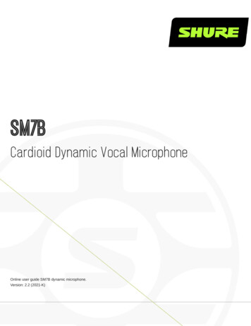
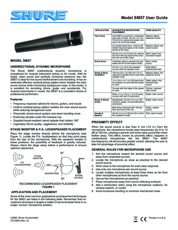
interference between them:WM700 / WM700D RECEIVERSee FIG. 1 at page 15:1. DC INSocket for the AC/DC adaptor connection, use only the adaptor supplied with the system.2. OUTPUT (UNBALANCED)Unbalanced output with line level: connect it through a mono 6.3mm jack cable to a mixer input.3. OUTPUT (BALANCED)Balanced output with mic level: connect it through a XLR cable to a mixer input.4. POWEROn/off switch.5. VOLUME (channel A or B)Volume potentiometer: set this control to a proper level that doesn’t saturate the mixer input channel.6. IRKeep this button pressed until the IR))) symbol lighted states, in this moment you can synchronize the frequency between thetransmitter and the receiver.7. IR port8. SET (channel A or B)Keep this button pressed until the number flashes and then push it again to set the frequency (1 – 8) CH A ; (9 – 16) CH B .9. Display (channel A or B)The display shows the frequency number (1 – 8) (9 – 16), that must correspond to the frequency set on the transmitter. In thislabel, together with the general data of the receiver, you can find the receiving radio frequency band.10. ANTENNAThese are the receiving antennas. Raise them up during the use and, to obtain a better reception, place the receiver away fromother metal objects and no more distant than 30m from the transmitter.WM7M HANDHELD TRANSMITTERSee FIG. 2 at page 16:1. MICROPHONE GRIDThe grid protects the microphone capsule and include a pop filter. Type of microphone capsule is dynamic with a cardioidunidirectional figure.2. IR SyncInfrared port to synchronize the frequency between receiver and transmitter3. Power switchholding down the button for one second the screen lights up and the microphone enters transmission mode. Pressing the buttonfor one second the word OFF appears on the screen and the transmitter turns off.4. FREQUENCY NUMBERThe display shows the frequency and channel number, that must correspond to the frequency set on the receiver. Note: when aflashing [LO] text appears, the batteries are near to be exhaust, to indicate that they must be replaced as soon as possible.5. BATTERIES COVERSliding down the lower part of the microphone body you can access to the battery inlet.6. BATTERIES INLETTo operate the microphone needs 2 type AA alkaline batteries.Note: the microphone is able to operate also with 2 Ni-MH rechargeable batteries, but in this case the operating time is less.7. FREQUENCYOn the back side of the batteries inlet an adhesive shows the frequency band of the transmitterWM7H BODYPACK TRANSMITTER
See FIG. 3 at page 16:1. AUDIO INPUT3,5mm mini jack input socket to connect the supplied microphones.2. OFF MUTE ONOn/off switch, downward the microphone is off, upward the microphone is on. There is a middle position where the microphone isturned on but it is muted, useful in case you don’t want to hear the typical switching on/off click.3. ANTENNAThis is the transmitting integral antenna: do not force, try to disconnect, or replace with other one.4. IRInfrared port to synchronize the frequency between receiver and bodypack transmitter5. FREQUENCY NUMBERThe display shows the frequency number, that must correspond to the frequency set on the receiver.Note: when a flashing [LO] text appears, the batteries are near to be exhaust, to indicate that they must be replaced as soon aspossible.6. BATTERIES COVERSliding down the lower part of the bodypack you can access to the battery inlet.7. SET BUTTONSUp and down buttons to manually set the transmitting frequency. IMPORTANT: be sure to not select the same frequency onthe two transmitters belonging to the same system because this will cause interferences and malfunctioning. To set thedistance of at least 500 kHz between two transmitters8. GAINUsing a PH1 Phillips screwdriver and rotating this trimmer is possible to optimize the gain of the microphone before its signal istransmitted. Rotate it clockwise if you want a higher gain (speaking) or rotate it counter-clockwise if you want a lower gain(singing).9. SENSITIVITYSelect between the two inputs sensitivity: L position LOW usually used with instruments. H position HIGH usually used for the Headset and Lavalier microphones like those supplied.10. BATTERIES INLETTo operate the microphone needs 2 type AA alkaline batteries.Note: the microphone is able to operate also with 2 Ni-MH rechargeable batteries, but in this case the operating time is less.11. CLIPClip to hook the Bodypack to the belt.12. FREQUENCYOn the back side of bodypack an adhesive shows the frequency band of the transmitter.TECHNICAL SPECIFICATION
FIG. 1
FIG. 2FIG. 3
IS A BRAND OFPROEL S.p.A.(World Headquarters – Factory)
Via alla Ruenia 37/4364027 Sant’Omero (Te) – ItalyTel: 39 0861 81241Fax: 39 0861 887862www.eikon-audio.comDocuments / ResourcesEIKON WM700 Wireless Microphone System [pdf] User ManualWM700 Wireless Microphone System, WM700, Wireless Microphone SystemRelated Manuals / ResourcesXvive Microphone Wireless System User ManualELEGIANT wireless microphone User ManualELEGIANT wireless microphone User Manual Product Introduction Power key SETkey short press to change working channel, panacom Wireless Microphone User Manualpanacom Wireless Microphone Thank you for purchasing MC-9707W Panacom’sWireless Microphone Please read the manual carefully before operating. Wireless Headphones User ManualWireless Headphones User Manual - Optimized PDF Wireless Headphones UserManual - Original PDFLeave a commentYour email address will not be published.CommentNameEmail
WebsiteSave my name, email, and website in this browser for the next time I comment.Post CommentManuals ,homeprivacy
EIKON WM700 Wireless Microphone System User Manual March 18, 2022March 18, 2022 Leave a comment on EIKON WM700 Wireless Microphone System User Manual . This warranty does not extend to damage resulting from improper installation, misuse, neglect or abuse. Proel S.p.A. will verify damage on returned units, and when the unit has been properly .