Transcription
Wi-Net Windowf WirelessNetwork AnalyzerUser's Guidewww.jdsu.com/know
owerButton
Table Of ContentsProduct Features 1About Your Wi-Net Window 2Main Unit Features 2LCD Indicators 4Instructions For Use 5Scan Testing Mode 6Ping Testing Mode 11Pinging Unsuccessful 13Main Setup Menus 16Ping Setup 19DHCP Mode On/Off 19Last DHCP 20Target Setup 22WEP Encryption Setup 24Expert Setup 29Signal Strength 30Scan Rate 32Service Set Identifier (SSID) 33Hidden SSID 34Entering an SSID 37Audio Setup 41Advanced Mode Option 42Shutdown Timeouts 43My MAC Address 44Status and Error Messages 45Internet Protocol Definitions 51
Battery Installation 56Important Note Regarding BatteryInstallation 57Specifications 58Customer Service (StandardServices) 59Technical Assistance 59Instrument Repair 59Product Repair 60Calibration 60Factory Upgrades 60Equipment Return Instructions 60Warranty Information 62
Product FeaturesWi-Net Windowf is a wireless networkanalyzer that detects and connectsto wireless equipment, reports signalstrength, pings IP addresses, andidentifies network components. Displays signal strength on LEDand as a percentage on the LCD Scans and logs all wirelesstransmissions in the area Identifies the name andtransmission channel of theequipment detected Works with IEEE802.11 b and gwireless devices Displays Internet access capabilityand encryption status on eachwireless component Identifies the signals as either anaccess point (infrastructure) orad-hoc Pings IP addresses and checks fora viable link to the Internet Negotiates with network DHCP toidentify components and IP/MACaddresses Operates on 4 AA batteries
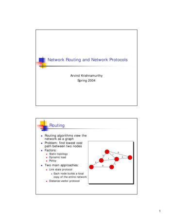
About Your Wi-Net WindowMain Unit Features87TMWi-Net Window21SEL34SETUPSCAN5PING6Figure 1. Main Unit Feature Diagram
Table 1. Main Unit FeaturesItemFeatureDescriptionArrow Keys are used fornavigation.1SELSelect the highlightedfunction or advance to thenext screen.3ScanPress Scan to search forwireless network devices.When unit is off, pressingthe Scan Button will powerup the device.4PingPress Ping to activate Pingtesting. When unit is off,pressing the Ping Buttonwill power up the device.25SetupPress the center of theScan/Ping button to enterSETUP mode. When unitis off, pressing the SetupButton will power up thedevice.Short press turns device onor toggles backlight on/off.Hold down until power off isdisplayed to turn off.67LED SignalStrength8AntennaThe signal strength of thewireless LAN (WLAN)detected displays on theLED bar graph.Wi-Fi antenna is pluggedinto coax connectors and isremovable.
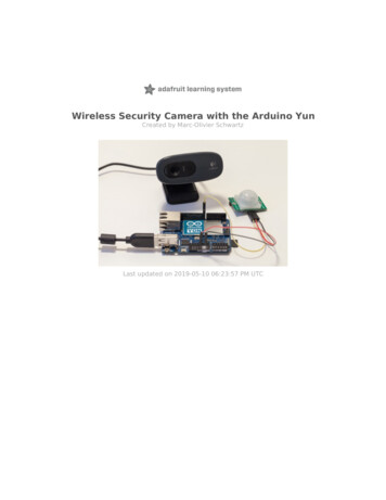
LCD IndicatorsChannelNumberNetwork ListPositionNetworkName (SSID)12 3 4 5 6 7 8ESignalStrengthActiveEncryptionInternetAccessQty. DetectedNetworksFigure 2. LCD Display
Instructions For UseTo turn on the Wi-Net Window press thePower, SCAN or SETUP key. To turnthe unit off, hold the Power key downuntil the display turns off. Briefly pressthe Power key to toggle the backlighton/off. The tester will automatically turnoff after 10 minutes of no activity (i.e. nokey press). See Shutdown Timeoutsin the Main Setup Menus section of thismanual for more timeout options.The Wi-Net Window includes two testmodes, Scan and Ping, which aredesigned to detect and connect towireless network equipment and verifyInternet access capability. Press theirrespective keys to enter these testmodes.All manually entered parameters, andadministrative options (e.g. audio,advanced mode, etc.), are saved whenthe Wi-Net Window is turned off. Toreset these to their factory-defaults,press the up arrow key while poweringthe unit on.
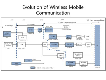
Scan Testing ModeScan Testing identifies wireless networkdevices and displays the network name(SSID) associated with the device. Thesignal strength of the wireless LAN(WLAN) detected displays on the LCD inpercentage format and also on the LEDbar graph at the top of the unit. (SeeFigure 3.)LED Light showingsignal strengthTMWi-Net Window2ESignal strengthshown in percentageFigure. 3Signal Strength MeasurementsWLANs detected during scan areordered by channel number and networkname (SSID). Use the arrow keys toscroll up and down the list of detected
WLANs. The WLANs relative positionwithin the list is depicted by illuminatingone of the fixed numbers (1-8) in thenumeric sequence above the SSID.(See Figure 4.)1 2 3 4E1 2 3 41 2 3 4Figure 4.Display of Detected WLANsDuring scanning a ping is sent tothe Internet IP every 15 seconds. Ifa response is received, an Internetindicator (i) is displayed. (See Figure 5.)1 2 3 4Figure 5. Display of Internet Indicator
If an Access Point (AP) is detected thatencrypts its data, the letter “E” displayson the LCD during scanning. If thedata is encrypted, Ping testing is notoperational. (See Figure 6.)2EFigure 6.Display of Detected Access PointIf two WLANs are using the same SSIDand channel, a twin status (t or twin)is displayed (they are differentiated bytheir MAC addresses). This can indicatea problematic network configuration oran attempt to initiate an “evil twin” scam.Additional network status is availablewhen operating in the Advanced Mode.See Advanced Mode Option in theMain Setup Menus section of thismanual for a complete list of statusindicators.Multiple presses of the SEL buttondisplay the unique IP address assignedto your Wi-Net Window, the Router’sIP address, and the Access Point MACaddress. (See Figure 7.)
SELSELFigure 7. Display of IP AddressEach of these displays are shown for upto 10 seconds. Press SEL to move pastthem more quickly.When operating with DHCP off, editingis allowed on the My IP and Rtr IPdisplays. Once editing starts, thedisplay remains active until accepted viathe SEL key, or canceled via the SCAN,PING or SETUP keys.If the router and access point are thesame, it is indicated by the caption “AP& Router IP.” (See Figure 8.)
Figure 8.Display of Router and Access PointPress SEL to display the correspondingMAC address. Since most wirelessnetworking hardware has a visibleMAC address label, this allows thecomponents of the wireless network tobe identified more easily.A scan for all hosts (AP’s) is initiatedevery 6 seconds. If a WLAN is notdetected after 4 scans (24 seconds),its signal strength is set to 0%. If thereis no activity after an additional 70seconds, the WLAN is removed fromthe scan. It may be removed earlier if amore active WLAN displaces it.The currently displayed WLAN islocked and will not be removed unlessyou scroll to a different WLAN or theunit is turned off. The Wi-Net Windowtracks and identifies up to 8 WLANssimultaneously based on signalstrength.10
Ping Testing ModeThe Ping test is used to verifyconnectivity to resources on or off thenetwork and IP addresses. The Pingtest can be run in DHCP or manualaddressing mode.During Ping testing, the channelnumber, SSID, ping target and countvalues for the transmitted and receivedping packets display on the LCD. TheWLAN signal strength displays on theLCD in percentage format and also onthe light bar at the top of the unit. (SeeFigure 8)2Figure 8.Ping Target and Count ValuesUse the left and right arrow keys to viewthe ping test results for the IP addressesassociated with the WLAN selected,including the Router, DNS, target IPaddresses 1-4, and the Internet.As you scroll through the respectivetargets during ping testing, press SEL toidentify the Wi-Net Window’s IP address,11
the IP address of the wireless networkdevice pinged, the length of time it tookfor the last ping, as well as the averageping response time in milliseconds. (SeeFigure 9)SELSELFigure 9.Scrolling Through Respective TargetsThe Ping Target IPs can be viewed andedited from this display. The Internet IPcan only be edited from the Target Setupsubmenu during Setup mode.12
Pinging UnsuccessfulWhen a ping target is selected, theWi-Net Window tests the currentlydefined network parameters anddisplays one of the following messagesif it is unable to send a ping. (See Figure10)TESTTESTTESTFigure 10. Unsuccessful Ping DisplaysThe problems that can prevent a pingfrom being successful include a nonexistent target (i.e. no ARP response),an invalid Router IP (when the target isnot on the local network), or when theunit’s IP address (My IP) is already inuse on the network.13
When starting Ping testing, the followingmessages may be displayed if aproblem or delay is encountered.Table 2.Message Display of UnsuccessfulPingingMessageDescriptionNo WLAN detectedcontinue to SCANNo WLAN has beendetected via SCAN sothere is nothing to ping.DHCP OffErr IP 0.0.0.0DHCP is not active and aManual IP has not beenentered.Ad-hoc networkno DHCP offeredAd-hoc WLANs do notsupport DHCP.Waiting on DHCPfor my IP XWaiting for a DHCP assignment; the number (X)is incremented for eachDHCP request ( every 10sec).DHCP On/OffVerifying AddrThe Manual, or DHCPassigned, IP is beingchecked via ARP to verifythat it is not already in use.My IP is in useon this networkSome other system isalready operating on thenetwork with the Wi-NetWindow’s assigned orManual IP.No DHCP locatedto assign My IPThere was no response tomultiple DHCP requestson the network.14
If no DHCP response is received, a pingis attempted every 10 seconds for 2minutes, then it stops.To restart the DHCP request cycle,press the Scan or Ping key. Whilescanning, you can also scroll off andback on the WLAN. If a DHCP assignedIP is already in use, the Ping test isretried after a one minute delay.Whenever possible, IP address screensare augmented with additional errorstatus messages. For a complete listof Error and Status messages, see theStatus and Error Messages section inthis manual.For example, if a specified Routeraddress does not respond to ARPrequests an error message “Rtr: Noresp.” displays. Also, if a Target IP is noton the local network, and the router isunresponsive “Tgtx: No Rtr” displays.15
Main Setup MenusPress the center of the Scan/Ping buttonto enter SETUP mode. The first fivesetup menus contain options related tothe Ping Test function. (See Figure 11)The last five setup menus containadministrative options, such as displaypreferences, audio tones, shutdowntimeouts, and the MAC addressassigned to your Wi-Net Window. (SeeFigure 12)Use the up and down arrow keys toscroll through the list of Setup Menuoptions. Press SEL to view or edit theinformation on each submenu.When you initially press SETUP, thepercentage of remaining charge on thebattery displays briefly. A Low Batteryicon indicates the battery should bereplaced as soon as possible. Seethe Battery Installation section of thismanual.16
SETUPSETUPSETUPSETUPSETUPFigure 11. Ping Setup17
SETUPSETUPSETUPSETUPSETUPFigure 12. Administrative Setup18
Ping SetupPing targets can be selected and editedduring Ping Testing. Press and holdSETUP to display the Ping Setup menu.Press SEL to view/edit the Manual IPor press the down arrow to advance tothe Router IP or Netmask submenus.When DHCP is off, this manuallyentered IP information is used for Pingtesting.To change the Manual IP, Router IP, orNetwork Mask, press SEL and use theright arrow key to position the cursorbeneath the digit you wish to change.Press the arrow key again to incrementthe value of the respective digit in the IPaddress up or down.Press SEL to save changes andnavigate to the next Ping Setupsubmenu. Press the Setup key tocancel editing without saving changes.At the bottom of the Ping Setupsubmenu, press SEL to return to theMain Setup Menu.DHCP Mode On/OffThe Ping test operates in either DHCPmode On (default) or Manual DHCPmode (Off). Press the down arrowkey to select the DHCP Mode On/Off19
submenu, then press SEL to toggleDHCP off or on. Press the down arrowto navigate to the next submenu.Last DHCPThe Last DHCP submenu identifiesthe DHCP Host information associatedwith the currently selected WLAN.Press SEL to view the IP informationassociated with the current DHCP Host,Router, DNS Server and Network Mask.(See Figure 13)SETUPSELSETUPFigure 13. IP InformationUse the up and down arrow keysto scroll through the Last DHCPitems. Press SEL to view an item’sMAC address. Since most wirelessnetworking hardware has a visibleMAC address label, this allows thecomponents of the wireless network tobe identified more easily.20
When a DHCP Host and its identifiedrouter have the same IP, they are shownon one screen. (See Figure 14)SETUPFigure 14.DHCP and Router with Same IPIf no information regarding thelast DHCP is available a messageconfirming this displays briefly. Pressthe down arrow to move to the nextsubmenu, view/edit Ping targets. (SeeFigure 15)SETUPFigure 15.No Information Shown for Last DHCP21
Target SetupPing testing includes four custom IPtargets (Tgt1-Tgt4), and an InternetIP. From the Target Setup submenu,press SEL to view and edit the targetIP addresses. Target IPs can also beviewed and edited while Ping testing isactive.Use the down arrow key to scrollthrough the Target submenus. PressSEL to view or edit the correspondingtarget IP. Use the right arrow key toposition the cursor beneath the digit youwish to change. Press the up or downarrow key again to increment the valueof the respective digit in the IP addressup or down. Once editing is complete,press SEL to navigate to the next targetand repeat the same process.Press SEL to save changes andnavigate to the next Target submenu.Press the Setup, Scan or Ping buttonsto cancel IP editing without savingchanges. At the bottom of the Targetsubmenus, press SEL to return to theMain Setup Menu. (See Figure 16)22
SETUPSELSETUPSELSETUPFigure 16.Navigate through Target Submenus23
WEP Encryption SetupThe WEP Encryption Setup supportsinteractive operation with wirelessnetworks that have 64-bit or 128bit Wired Equivalent Privacy (WEP)encryption. This is the originallyspecified form of wireless encryptionand consequently is supported by mostexisting hardware.On the Wi-Net Window you define oneWEP key to use when communicatingwith encrypted wireless networks.This key is applied to all networksthat are detected as being encrypted.To enter the WEP key you need tospecify the key size (64 or 128 bit), theauthentication type (Open System orShared Key), the active key position(1-4) and the hex digits that comprisethe key value. When in doubt as tothe authentication type, choose OpenSystem to start.From the Encryption submenu,press SEL to view and edit the WEPEncryption setup. Use the downarrow to scroll through the Encryptionsubmenus. Press SEL to view or editthe corresponding WEP Encryptionchoices. (See Figure 17)24
SETUPSETUPSETUPSETUPSETUPFigure 17.Encryption Setup Sup-MenuHex digit entry is similar to entering anIP address on the Wi-Net Window. Usethe right/left arrow keys to position thecursor beneath the digit you wish tochange. Press the up or down arrowkey to increment or decrement the valueof the corresponding digit. Digit entrysupports rollover so you can incrementfrom an ‘F’ to a ‘0’ and vice versa.25
When entering a 128-bit WEP valuethere are 3 “pages” for entering the 26hex digits. Scrolling right or left off ofone page connects to the next. Thecurrent page number (1-3) is displayedas a fixed number above the WEPvalue. (See Figure 18)SETUPSELSETUPSETUPSETUPSELSETUPFigure 18.Entering 128-bit WEP Value26
Once the WEP value is entered, pressSEL to always save changes and returnto the next Encryption submenu. Pressthe SETUP, SCAN or PING key to exitWEP editing and start the selectedoperation. When exiting in this manner,if the WEP key value has changed, youare presented with the option to savethe changes (SEL), discard the changes(Down Arrow) or cancel and return toWEP editing (Up Arrow). (See Figure19)Figure 19. Save ChangesYour WEP settings are retained whilethe Wi-Net Window is off and evenduring a battery change.You need to know your encryptionparameters whenever you setup awireless client or connect with theWi-Net Window. For convenienceyou should make a note of them soyou don’t need to read them from theAP each time. It is also good to writedown the Access Point’s IP address27
so you can quickly connect with it forreview or to make changes. ManyAccess Point manuals have a placefor jotting this information down. Ofcourse since these are your network’ssecurity settings, they should be kept ina protected location.28
Expert SetupExpert Setup supports three advancedfeatures. These features includealternate signal strength measurementunits, a variable scan rate and supportfor connectivity to access points withhidden SSIDs. The following sectionsdescribe these additions in detail. (SeeFigure 20)SETUPSELSETUPSETUPSETUPSETUPFigure 20.Expert Setup Submenus29
Signal StrengthThe Wi-Net Window displays signalstrength as a percentage value. Thisvalue represents an overall signalquality based on several measuredparameters. This format was selectedbecause it is widely understood by mostpeople.For more technical users a signalstrength measurement in dBm issometimes preferred. dBm is anabbreviation for the power ratio indecibel (dB) of the measured powerreferenced to one milliwatt (mW). It isused in radio, microwave and fiber opticnetworks as a convenient measure ofabsolute power because of its capabilityto express both very large and verysmall values in a short form. Zero dBmequals one milliwatt. A 3 dB increaserepresents roughly doubling the power,which means that 3 dBm equals roughly2 mW. For a 3 dB decrease, the poweris reduced by about one half, making 3dBm equal to about 0.5 milliwatt.To change the signal strength displaySEL Expert Setup from the Main Setupmenu. Press the SEL key to cyclebetween dBm and percentage (%). (SeeFigure 21)30
SETUPSELSETUPFigure 21.Signal Strength Display SetupWhen dBm is selected the CAL iconis shown on the scan display. The 10LEDs on the Wi-Net always indicate thepercentage signal strength. (See Figure22)1 2CAL4 5 6 7 8 SEFigure 22.Display of CAL IconFor wireless networks the signalstrength ranges from around –20 dBm to–90 dBm. When the AP is out-of-rangethe signal strength is displayed as –99dBm.31
Scan RateThe Wi-Net Window actively scansfor existing wireless networks. Activescanning is much quicker and moreresponsive than passive scanning. Bydefault the Wi-Net scans the current(i.e. displayed) network once every twoseconds and scans for all networks onceevery six seconds. If a hidden SSID isspecified (See Figure 25), it is scannedevery four seconds. Since activescanning requires more power, theserates were chosen as a reasonablebalance between functionality andbattery life.To change the Scan Rate SEL ExpertSetup from the Main Setup menu. Pressthe SEL key to cycle through the list ofrates (in seconds): 0.5, 1.0, 1.5, 2.0, 2.5,3.0. (See Figure 23)SETUPFigure 23.Scan Rate OptionsNote that the faster scan rates canpotentially decrease battery life.32
Service Set Identifier (SSID)A Service Set Identifier (SSID) is a32-character name that, along with achannel num
Wi-Net Windowf is a wireless network analyzer that detects and connects to wireless equipment, reports signal strength, pings IP addresses, and identifies network components. Displays signal strength on LED and as a percentage on the LCD Scans and logs all wireless transmissions in the