Transcription
View metadata, citation and similar papers at core.ac.ukbrought to you by 2015. This manuscript version is made available under the CC-BY-NC-ND 4.0 d/4.0/Experimental investigation of the applicability of athermoelectric generator to recover waste heat from acombustion chamberP. Aranguren, D. Astrain*, A. Rodríguez, A. MartínezDepartamento de Ingeniería Mecánica, Energética y de Materiales, Universidad Públicade Navarra, Pamplona (Navarra), España*Tel: 34 948 169597, Fax: 34 948 169099, e-mail: david.astrain@unavarra.esKeywords: thermoelectricity, prototype, combustion chamber, waste heatAbstractA thermoelectric generator prototype has been built; it produces 21.56 W of net power,the produced thermoelectric power minus the consumption of the auxiliary equipment,using an area of 0.25 m2 (approximately 100 W/m2). The prototype is located at theexhaust of a combustion chamber and it is provided with 48 thermoelectric modules andtwo different kinds of heat exchangers, finned heat sinks and heat pipes. Globally, the 40% of the primary energy used is thrown to the ambient as waste heat; one of the manydifferent applications in which thermoelectricity can be applied is to harvest waste heatto produce electrical power.Besides, the influence on the thermoelectric and on the net power generation of keyparameters such as the temperature and mass flow of the exhaust gases, the heatdissipation systems in charge of dispatching the heat into the ambient and theconsumption of the auxiliary equipment has been studied. In terms of heat dissipation,the heat pipes outperform the finned dissipators, a 43 % more net power is obtained.NomenclatureϵσeℎℎAbsolute errorRelative errorEmissivityNet efficiencyEfficiency of the thermoelectric generatorGlobal efficiencyStefan-Boltzmann coefficientExternal areaRadiation areaSpecific heatThicknessExterior convection coefficientRadiation coefficientIntensity consumed by the auxiliary equipmentIntensity produced by the TEMsThermal conductivityMass flow of the exhaust gasesHeat emitted to the ambient by the TEGHeat absorber by the TEGCOREprovided by Academica-eW/m2K4m2m2J/kgKmW/m2KW/m2KAAW/mKkg/sWW1
"#! ##%& ## ' (#%& ##%& ## ' (#%& " "## " " "(# ) )## ) )(# ** ##(#Conduction thermal resistanceContact thermal resistanceConvection thermal resistanceThermal resistance of the isolationLoad resistanceRadiation thermal resistanceInterior resistance of the TEMTemperature of the cold side of the lower levels finned dissipatorsTemperature of the cold side of the lower levels heat pipesTemperature of the cold side of the upper levels finned dissipatorsTemperature of the hot side of the lower levels finned dissipatorsTemperature of the hot side of the lower levels heat pipesTemperature of the hot side of the upper levels finned dissipatorsTemperature of the exhaust gas at the inlet of the elbowTemperature of the exhaust gas at the inlet of the lower levels ofthe TEGTemperature at the beginning of the exhaust channelTemperature of the exhaust gas at the inlet of the nozzleTemperature of the exhaust gas at the inlet of the upper levels ofthe TEGMean temperature of the exhaust gas at the elbowMean temperature of the exhaust gas at the lower levels of theTEGMean temperature of the exhaust gas at the nozzleMean temperature of the exhaust gas at the upper levels of theTEGTemperature of the exhaust gas at the outlet of the elbowTemperature of the exhaust gas at the outlet of the lower levels ofthe TEGTemperature of the exhaust gas at the outlet of the nozzleTemperature of the exhaust gas at the outlet of the upper levelsof the TEGTemperature at the end of the chimneyVoltage consumed by the auxiliary equipmentVoltage produced by the TEMsPower consumption of the auxiliary equipmentNet generated powerTEG power �C⁰C⁰CVVWWW1. IntroductionThe development of the modern civilizations is characterized by a sharp rise in the energyconsumption. This fact has resulted into an untenable energetic system with significantenvironmental impacts. One of the essential challenges of today’s societies is energeticsustainability aiming to stimulate energetic models with low carbon consumption and lessenergetic consumption. Two are the cornerstones to achieve the energetic challenge: thedevelopment of renewable energies and the improvement of the energetic efficiency. Inthe past decade, the development of the renewable energies has been very noticeable; in2012 the 21.7 % of the worldwide electric energy consumed was produced by greenmeans [1]. Nevertheless, the 80 % of the energy that is consumed by the human beingscomes from the use of fossil fuels [2]. This fact outlines the efficiency importance of the2
combustion processes, still nowadays the majority, as well as the impact of a betterrecovery of the heat generated at the combustion processes, reducing to the minimum theunused waste heat. The 40 % of the primary energy used is being thrown to the ambientas waste heat [3].Thermoelectric generation (TEG) has attracted the attention of many researchers due toits capacity to produce electric energy from waste heat originated at very differentapplications, from industrial processes to domestic boilers. The main element of a TEGis the thermoelectric module (TEM) which is in charge of turning heat into electricity. ATEM is a thermal machine where the electrons are the working fluid, eliminating themoving parts and thus providing to the TEGs with their inherent advantages, such as lackof maintenance, easiness of control, reliability and robustness [4].Large amounts of heat are emitted by the industry with too low temperatures ( 200 ⁰C)to be used by conventional energy conversion systems. This unused energy is wasted intothe ambient. A theoretical study on the collocation of TEGs at 27,000 industrial firms ofThailand provided with diesel cycles and turbines was conducted obtaining 100 MW ofpower generation [5]. Alike, the 40 % of the fuel energy is thrown to the ambient by thetailpipe of the vehicles [6]. Studies obtain fuel reductions of the 8-12.5 % bythermoelectric means [7].To address the thermoelectric phenomena two approaches are used by the researchers,computational simulation and experimental prototypes. The computational simulatorssolve the thermal and electrical dynamics of thermoelectricity (TE). Differentcomputational software is used such as Matlab and Simulink via the resolution of blocksthat represent the whole system [8], Mathcad using dimensional analysis [9], TRNSYSvia a novel TEG model incorporated to the TRNSYS standard library [10] or Matlab viafinite differences [11]. The computational models simulate the thermoelectric behaviour;e.g. a theoretical study concluded that a TEG located on the tailpipe of an average carcould meet the electrical needs of that vehicle [12].The prototypes or test benches obtain experimental results. Most of the times theexperimental data is used to validate a computational model, so that the conditionssimulated are quite idealized, a chimney modelled with a blower and a boiler to simulatethe flue gas from a boiler or a stove [13] or a prototype installed at a car tested at constantvehicle speed and constant engine rotation [14] when it is known that driving conditionsset the waste heat ejected by vehicles with temperatures ranging from 100 to 800 ⁰C. Theconsumption of the auxiliary equipment is not normally taken into account, [15] presentsa study on the potential of recovering low-temperature waste heat by thermoelectrics inwhich the power of the fan used to cool down the device is not present in the results. Thispaper presents a prototype built at the exhaust of a combustion chamber working underreal conditions.TEGs installed at big scale applications have the potential to generate electric energyrecovering waste heat, improving the overall efficiencies of energy conversion systems,reducing the emissions of CO2, and hence helping to reduce the global warming. In thispaper a prototype shows the possibilities that thermoelectric generation has if applied torecover waste heat from exhaust steams at industry applications. A TEG composed by 48TEM located at the exhaust of a combustion chamber has been built to that purpose. Astudy on the influence of key variables of the waste heat, temperature and mass flow hasbeen developed. Previous scientific researchers present differet ways of optimizing thethermoelectric generation. The optimization of the heat exchangers present at the TEGgreatly influence the electrical power generation [16], the electrical current produced,3
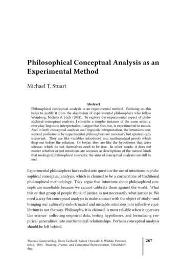
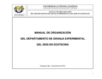
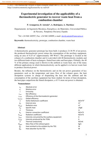
therefore the influence of the load resistance, is also a key factor [17] as well as theoccupancy rate of the thermoelectric generators [18] and the working conditions [19].Inthis paper, to characterize the influence of the dissipation systems placed on the cold sideof the generator and to test the influence of the load resistance a study has been doneplacing finned dissipators and heat pipes at the prototype trying to search the optimalpoint via different load resistances.The consumption of the auxiliary equipment has also been taken into account, because asit has been demonstrated, the consumption of the auxiliary equipment is crucial to obtainthe optimal working point, the maximum net power generation. The configuration wherethe maximum power is generated, it is not necessarily the optimal point [20]. This studypresents a real situation of net power generation, the useful power obtained by waste heatrecovery at a combustion chamber.2. Design and construction of the prototypeA TEG is a device that converts heat into electricity via the Seebeck effect. It is composedby one or more TEMs connected in series. Part of the heat that arrives to the hot side ofthe TEMs ( ) is transformed into electric power ( ). The rest of the heat ( ) isdissipated to the cold sink, normally the ambient, through the cold side of the TEMs.Figure 1 presents the behaviour of a TEG. The thermoelectric energy production increases as the temperatures of the cold and hot sides approach the temperatures of theheat source and heat sink respectively, this statement does not necessarily mean that theefficiency of the TEG, -./012, increases as Apertet et al. concluded in [19].Nevertheless, as the objective of this prototype is to recover waste heat, the main objectiveis to maximize the thermoelectric power production. This is why heat dissipation systemsneed to be attached to both sides of the TEMs in order to pull the hot and coldtemperatures towards the temperature of the heat source and heat sink respectively.Figure 1. Thermoelectric generator behaviourIn order to study the potential of thermoelectric generation out of waste heat recovery aprototype has been built to be collocated at the exhaust of a combustion chamber, Figure2 presents the whole prototype. Part of the chimney that connected the combustionchamber with the exterior was modified to accommodate the TEG. The generator iscomposed by 48 TG12-8-01L TEMs disposed along a flat surface of approximately 0.25m2. Their maximum peak working temperature is 250 ⁰C at their hot side thanks to their4
special welding [21]. The TEG is divided into 12 thermoelectric units (TEUs), each ofthem is provided by a cold side heat exchanger, a finned dissipator or a heat pipe. Twodifferent heat exchangers have been included into the prototype to state whether the noveldevices outperform the conventional ones, the finned dissipators.Figure 2. TEG prototype at the exhaust of the combustion chamberA combustion chamber has been used. Any fuel can be used, even though the only fuelused for these experiments has been natural gas. The mass flows of the fuel (natural gas)and oxidizer (air) can be selected; therefore different temperatures and mass flows of theexhaust gases can be obtained. The properties of the combustion chamber can be foundin Table 1. The combustion chamber measures the temperature of the smoke when itleaves the chamber by a thermocouple probe able to measure up to 1000 ⁰C. Thistemperature can be defined as the temperature of the gases at the beginning of the exhaustchannel ( " ).Maximum combustion power (kW)Maximum temperature of the exhaust gases (⁰C)Air mass flow (kg/h)Fuel mass flow (kg/h)Refrigeration water mass flow (kg/h)Dimensions (mm3)Weight (kg)1508000 – 1602.2 – 19.4500 – 18002750 x 1000 x 2000330Table 1. Characteristics of the combustion chamber5
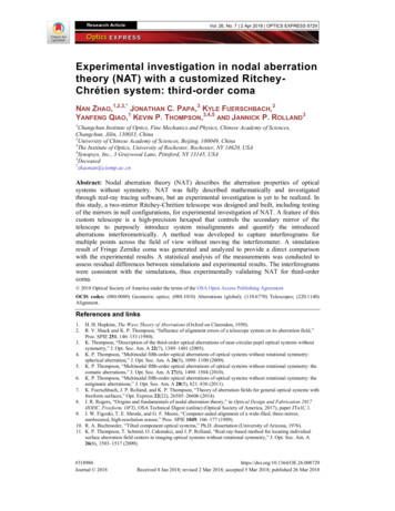
The chimney was accommodated to house the TEG. The cylindrical shape wastransformed to a 0.26 x 0.26 m2 quadrangular section. The square chimney has a nozzleon one end to connect the TEG with the previous round-shape chimney. The interior andexterior walls are flat. In the inside of the chimney the exhaust gases circulate transferringtheir heat to the flat wall while on the exterior surface the TEMs that form the TEGprototype are placed. Once the smoke has feed the TEG, it is collected and conducted tothe exterior by the original chimney. The material of the whole chimney is stainless steel.Figure 3 shows the location of the 12 TEUs on the prototype, as well as how the TEMsare located on each TEU. A TEU is formed by four thermoelectric modules and one heatexchanger, a finned dissipator or a heat pipe depending on the kind of TEU.The TEUsare disposed on two opposite sides of the conduct, specifically 8 on one side and the other4 on the opposite side. The four TEMs of each TEU are disposed as a 2 by 2 matrix. Theyare thermally in parallel and electrically connected in series. Isolation in between theTEMs is present in order to force the heat to flow through the TEMs, hence, producingmore electric power. The isolation thickness corresponds with the thickness of the TEMs,3.5 mm, and is made out of rockwool. The heat exchange area of each unit, including theextra area to host the bolts in charge of assuring good contact, is 0.12 x 0.156 m2. TwoTEUs per level of the chimney are installed, a total of four and two levels respectively oneach side as it can be seen in Figures 2 and 3. The first two levels, the lower levels wherethe LLFD and LLHP are located, are isolated from the ambient by an isolation panel of athickness of 3 mm and a thermal conductivity of 0.15 W/mK located on the surfaces thatdo not have TEMs,. However the last two levels, where the group ULFD is located, donot present any isolating surface to prevent the heat loss to the ambient.Figure 3. Detail of the TEUs (Thermoelectric units). Distribution of the TEMs on eachTEU and electrical connections of each group.Each TEU is provided by one heat exchanger on its cold side. The heat exchangers areresponsible for conducting the heat to the ambient. Two different kinds of dissipators arepresent in this prototype: finned dissipators and heat pipes. Both of them have the samebase area on which the TEMs are located, 0.12 x 0.156 m2. A total of 8 finned dissipatorsare located on the TEMs of one side while 4 heat pipes are present on the opposite side,as it can be seen in Figure 3.6
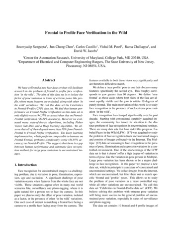
The base thickness of the finned dissipators is 7.5 mm with a fin height and thickness of20.5 and 1.5 mm respectively and a fin spacing of 3.5 mm. The detail of the finneddissipators is in Figure 4a). They are made of aluminium and have four holes, one on eachcorner, to ensure the proper assembly of the TEUs to the chimney which is provided withhomologous threaded holes. To make air circulate over the fins, four fans in total arepresent, two TEUs share the same fan. Each wind tunnel is disposed horizontally coveringthe two TEUs that are at the same level.Figure 4 b) presents the other kind of heat exchanger, the heat pipe. A heat pipe is apassive two-phase heat transfer device capable of transferring large quantities of heat witha minimal temperature drop. A classical heat pipe consists of a sealed container lined witha wicking structure [22]. The designed heat pipes have a total of 10 copper plated tubesof 350 mm of length, 8 mm of diameter and a spacing of 5 mm. The capillary system issinter and the working fluid water. Each tube can transport up to 61 W of heat. Thecondensation of the water is helped out with fins present at one end of the tubes. The finsare 130 x 55 x 0.3 mm3 and are provided with ten holes to host the tubes. The fin spacingis 3 mm. To help air circulate through the fins, one wind tunnel per heat pipe has beenmounted at the prototype. Figure 2 shows the complete TEG.a)b)Figure 4. Heat exchangers on the cold side, a) finned dissipator, b) heat pipe.Each wind tunnel has a fan with a maximum power input of 5.4 W. The fans are SunonMEC0251V1 with dimensions 120 x 120 mm2. In order to study the influence of theexternal convection with the ambient, different experiments were made with differentpower inputs of the fans.Two units formed by different fixed load resistances have been built. The objective ofthese devices is to provide the TEG with different load resistances, as the combination offixed resistances, and hence study the maximum power output of the thermoelectricsystem. Four different fixed resistances are present: 1, 2.2, 4.7 and 10 Ω. These units canbe seen in Figure 2 under the name “Resistance units”.Three groups were made with the 12 TEUs installed at the prototype. Each group isformed by four TEUs and it represents a kind of heat exchanger particularized for a heightof the chimney. There are two groups of finned dissipators, one placed at the two lowerlevels (LLFD) and the second one on the upper ones (ULFD), and one heat pipes grouplocated at the two lower levels (LLHP). Figure 2 depicts the three different groupsformed.Figure 5 presents all the measurement probes used. The TEG is fully monitored bydifferent kinds of measuring instruments. Three smoke temperature probes located at the7
inlet and outlet of the TEG. One smoke flow meter provided with a temperature sensorlocated at the outlet of the TEG as it can be seen in Figure 5. Fourteen surface temperatureprobes located in between the hot sides of the TEMs and the surface of the chimney tomeasure the hot temperature of the TEMs. Fourteen surface temperature probes locatedin between the cold sides of the TEMs and their corresponding heat exchanger, theymeasure the cold temperature of the TEMs. The cold and hot temperature measuringprobes are located at the same spot of the hot side temperature probes. The location ofeach probe can be seen in Figure 5.Figure 5. Location of the measurement probes at the prototypeThe inlet temperature of the smoke to the TEG ( "## ) is obtained by 3 45 6 and 3 45 7while the outlet temperature is obtained by 3 45 8 and 3 45 . Four probes of eachkind obtain the hot and cold temperatures of the ULFD group ( 8 , 6 , 7 and 9 obtain (#%& and 8 , 6 , 7 and 9 obtain (#%& ), six of a kind obtain thetemperatures of the LLFD ( : , : , , , ? and ? obtain ##%& and : , : , , , ? and ? obtain ##%& ) and four hot and cold temperature probes thetemperatures of the TEMs of the LLHP, ( @ , 8A , 88 and 86 obtain ## ' and @ , 8A , 88 and 86 form ## ' ). Four ammeters and four voltmeters prepared to measurethe output voltage and intensity of the TEMs.The surface temperature probes are K type probes, their insulation (glass fiber) allowthem to support temperatures as high as 400 ⁰C. The smoke probes are sheathed sensorstype K able to support up to 1100 ⁰C. The smoke flow meter is a thermal mass flowmeterfor gas measuring applications. Its measuring flow range is 0-250kg/h and its maximumworking temperature is 480 ⁰C. Both the ammeter and voltmeter are digital with a8
sampling rate of 1kHz and a resolution of 12 bits ( 2048 digits). In Table 2 the resolutionand the accuracy of all the measurement instruments can be found.3. Experimentation methodologyDifferent variables were modified to obtain a complete study on the influence of theparameters over the thermoelectric power generation as well as over the net generation.The net power generation corresponds with the generation power minus the consumptionof the auxiliary equipment, the goal to maximize. It has been demonstrated that the powerconsumption of the auxiliary equipment is necessary to take into account to optimize aTEG [20]. The maximum generated power working point did not correspond with themaximum net power generation working point. (1)Equations (2) and (3) present the absolute experimental error of the generated power( ) [23]. The absolute error of the measuring instruments can be found in Table 2.The relative error of the generated power is expressed in equation (4). Consequently, theabsolute experimental error of the net generated power is presented in equation (5).(D) FG( W W W X T YZT*[6 (*HIH JK6) RS(L8 XT ) ZT6 GT T*W X )6X [UYZ6HIH N6T T*(K6(L6(*[)6 G)6 S6(*T ) ZT*6 T T[6H PU)6 Z HI6K6(T T(*(L)6Q(2)86)6 V[6(T ) ZT6JN(3))6 \[686(4)() \686(5)The 100 % of the experimental relative errors of the generated power are smaller than the6 % while the 90 % of the experimental relative errors of the net generated power staybelow the 6 % due to the consideration of the power consumption of the auxiliaryequipment in the calculation of the net power generation.The “resistance units” have been used to seek the maximum power generation. There isvariable resistance associated to each TEM (). The TEUs of each group areconnected in series and parallel. A total of four TEUs form each group. Two parallelbranches, each one formed by two TEUs in series, are connected to the load resistancesin order to obtain the thermoelectric generated power, Figure 3 presents the electricalconnections. . The resistance is a function of the temperature of the hot and cold sides of9
the TEM. The load resistance ( # ) that maximizes the power generation is the one thatequals the interior resistance of the TEM at the working point [24], so that, it is necessaryto modify the load resistance in order to find the maximum power generation. Varyingthe load resistance Figures 7 to 10 can be obtained, showing the influence of the loadresistance over the thermoelectric generated power. The load resistance values have beenselected taking into account how the TEUs are electrically connected inside each group,see Figure 3, so that the optimum in generation can be achieved.To quantify the influence of the parameters on the power generation, on both thegenerated power and the net power, experimentation varying the temperature of thesmoke, the mass flow of the smoke, the load resistance and the power consumption of theauxiliary equipment was performed.SensorResolutionSmoke temperature (combustion chamber ⁰C)1Surface temperature (⁰C)Smoke temperature (⁰C)0.10.1Smoke flow meter (kg/h and ⁰C)Ammeter (A)Voltmeter (V)0.10.10.010.1Accuracy 1 0.5 0.5 1 % measured value 0.5 % full scale 1.2 0.02 0.2Table 2. Resolution and accuracy of the measuring instruments4. Results and discussionA first study to determine the amount of heat lost through the surfaces which lack ofthermoelectric devices, as well as the heat lost via the isolation that surrounds the TEMshas been made. An analytic calculation has been made using experimental data obtainedfrom an open circuit experiment.The chimney has been divided into four blocks: the elbow, the nozzle, the lower levels ofthe TEG and the upper levels of the TEG. Each block is separately solved to obtain thetemperature of the exhaust gases at the exit, and thus the inlet temperature of the nextblock is obtained. The temperature of the gases at the exit of the combustion chamber( " ) is known, as well as the temperature at the inlet of the first block of the TEG ( "## )and the exit temperature ( ), the temperature of the exhaust gases after feeding thewhole TEG. Table 3 and Table 4 present the results obtained. In the experimentation theTEMs are in an open circuit, so that any of the thermoelectric phenomena occurs and nopower is being generated. As the interior coefficient of convection is the biggestunknown, the methodology used is to obtain the interior convection coefficient thataccomplishes the temperature drop along each different block. Figure 6 presents theblocks and their electrical analogy. It is important to note that the first block of the TEG,the lower levels, contains four TEU provided with finned dissipators and four with heatpipes while the second block, the upper levels, solely contains four TEU provided withfinned dissipators.10
Figure 6. Electrical analogy of the block of the chimneyThe inlet temperature of the exhaust gas of each block equals the outlet temperature ofthe previous block, so " , the temperature at the exit of the elbow blow equalsthe temperature at the entry of the nozzle block and so on. The mean temperature of eachblock ( ) ) is obtained applying the arithmetic media of the inlet and outlet temperaturesof the block, ) 1/2( " ). ab (⁰C) cde (⁰C) aff (⁰C) ghi (⁰C)hjgk (kg/h)Experimental value621477.0559.135.8115.0Table 3. Parameters of the open circuit experimentationThe thermal resistances have been calculated using expressions that can be found in theliterature as well as through experimental data. Equation (6) presents the conductionthermal resistance applied to the isolation and the conduction present in the walls of thechimney. The thermal conductivities are 0.15 and 15 W/mK respectively for the isolationand the stainless steel. Equations (7) and (8) present the radiation of a body contained ina room. The external convection thermal resistance has been calculated through equations11
(9) and (10). The external Nusselt number has been obtained using Churchill andBernstein expression [22] for forced convection. The external convection coefficient isapproximately 4 W/m2K using a velocity of the exterior air of 0.5 m/s. ℎ "ℎ1 l(6)(7)6 σϵ(Tn6 Topq)(Tn Topq )(8)ℎ(9)! 198 ƒ8w: :?ℎ t0.62 l 6 } 7 ‚lvrs v0.3 [ †8 ‚ „1 Z2820006 9‚v0.4 7 1 G K }u (10)The thermal resistances of the heat exchangers, the finned dissipators and the heat pipes,have been obtained through previous experimentation. The thermal resistance of eachfinned dissipator and heat pipe are 0.18 and 0.075 K/W respectively. The thermalresistance of each TEM () is provided by the manufacturer, 1.2 K/W [21]. Thecontact resistances present stay in between 0.32 and 0.39 K/W per TEM, while the contactresistances of the isolation surrounding the TEMs of each TEU is 0.1 K/W.Table 4 presents the temperatures obtained experimentally and computationally. Thesetemperatures have been achieved through the open circuit simulation. The hotexperimental temperature of the TEUs that own finned dissipators at the first block of theTEG ( %& ‡8 ) is greater than the computationally obtained. This difference can beattributed to the contact of the temperature probe which is obtaining a false temperatureat the hot side of the TEMs. The internal convection coefficients obtained correspond to34.9 W/m2K at the elbow and nozzle and to 14.8 W/ m2K at the TEG. ˆff‰Š (⁰C) ‹ff‰Š (⁰C) ˆffˆŒ (⁰C) ‹ffˆŒ (⁰C) ˆ f‰Š (⁰C) ‹ f‰Š (⁰C)Experimental value143.574.0125.350.3122.061.9Computational value142.8168.38125.1149.98121.9361.57Table 4. Experimental and computationally results obtainedThe results obtained, contribute to a better understanding of the heat lost distributionalong the chimney. Due to the design of the chimney, just the 50.4 % of the heat that istaken from the exhaust gases at the TEG (the two last blocks) goes through the TEMs(1758 W) while the 8.4 % crosses the isolation located around the TEMs (295 W). The12
rest, the 41.2 % is lost via the free surfaces as convection or a combination of convectionand radiation (1438.6 W). The first block of the TEG is totally isolated from the ambientwith 3 mm thickness rockwool, while the second one is not. Before the smoke arrives tothe TEG an important heat lost exists, the heat that is transferred to the ambient via thesurfaces of the elbow and the nozzle. It corresponds to the 45 % of the heat loss of theexhaust gases (2849.1 W), while the other 55 % is lost to the ambient at the TEG itself(3492 W). Figure 6 presents the electrical analogy of the whole chimney.Different studies varying the parameters of operation have been developed, thetemperature of the exhaust gas, its mass flow and the power consumption of the auxiliaryequipment have focused the attention.4.1. Influence of the mass flow of the exhaust gasThree different mass flows were tested, 67, 84 and 118 kg/h. These values were obtainedmodifying the mass flows of the natural gas and the air introduced into the combustionchamber. The temperature was maintained constant along the whole experimentation; theexhaust gases left the combustion chamber at 591 ⁰C. To test the influence of theconsumption of the fans over the thermoelectric generation, two power consumptions perTEU were tested 1.11 and 5.40 W. Table 5 presents the details of the experimentation. ab (⁰C)Mass flow (kg/h)59167.083.7118.252556059167.0 ab Ž (⁰C)504.5514.2528.7459.8476.8504.5 cde (⁰C)428.4450.6472.8405.7407.0428.4Table 5. Temperatures and mass flows of the experiments conductedFigure 7 shows the dependency of with respect to the load resistance for differentexhaust gas mass flows and the auxiliary power consumptions. There is a differencebetween the thermoelectric generation when the consumption of the auxiliary equipmentis the biggest (filled markers) and the generation when the consumption is the smallest(empty markers). Nevertheless, despite the generation is greater in the case where moreconsumption from the auxiliary equipment is needed, the difference in generation doesnot justify it. As the preferences of auxiliary power consumption depend with theapplication itself: the type of heat exchanger, the exhaust gas mass flow and thetemperature of the exh
by one or more TEMs connected in series. Part of the heat that arrives to the hot side of the TEMs ( ˆ ) is transformed into electric power ( ˆ ). The rest of the heat ( ˆ ) is dissipated to the cold sink, normally the ambient, through the cold side of the TEMs. Figure 1 presents the behaviour of a TEG. The thermoelectric energy .