Transcription
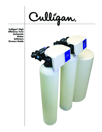
Installation Instructions for Water Softeners with Fleck 5600and 5600SXTCovers standard water softeners using a separate brine tank.THANK YOUThank you for purchasing a new Water Softener from Oceanic WaterSystems. We appreciate the opportunity you have given us to provide youwith better water. We are committed to providing the best customerexperience possible and have provided these installation instructions tomake things as simple as possible. If you have read through these entireinstructions and FAQ section and still have questions feel free to contactus for further help. Our office hours are Monday-Friday 10:00 AM - 4:00PM PST, and you can call us at 661-575-0033.BEFORE YOU BEGIN BASIC PLUMBING SKILLS ARE REQUIRED FOR INSTALLATION. IF YOU ARE UNSURE OF YOURABILITIES TO INSTALL THE SYSTEM USING THESE INSTRUCTIONS PLEASE HIRE A QUALIFIEDPLUMBER. READ THROUGH YOUR PARTS LIST AND VERIFY ALL COMPONENTS ARE ACCOUNTED FOR ANDIN GOOD CONDITION BEFORE SCHEDULING A PLUMBER. PLEASE READ THROUGH THE ENTIRE INSTRUCTION MANUAL CAREFULLY. IF HIRING APLUMBER ENSURE THEY HAVE A COPY BEFORE THEY START. MOST COMMON QUESTIONS ARE ANSWERED IN THE INSTRUCTIONS OR FAQ SECTION. IFYOU HAVE READ BOTH OF THOSE AND STILL HAVE QUESTIONS YOU MAY CONTACT US FORFURTHER HELP. PLUMBING RELATED QUESTIONS NEED TO BE DIRECTED TO A LOCALLY QUALIFIED PLUMBER.WE ARE NOT PLUMBERS AND ANY PLUMBING QUESTIONS WE RECEIVE WILL NOT BEANSWERED.
SYSTEM REQUIREMENTSYour chosen installation location and water supply must meet ALL of the followingrequirements: 20-90 PSI (1.38-6.20BAR) 34-110 F (1.1-43.3 C) System must be protected from freezing Firm level surface AFTER the pressure tank 3-prong, 120V outlet within 5 ft. (1.5 m) of the control head with constantpower. GFCI outlet is recommended. Use of an extension cord is NOTrecommended.A 1.5-inch standpipe, sump pit, or outside drain. Please note: The drain lineis pressurized and can be ran vertically if necessary.1. VERIFY SYSTEM INVENTORY System SizeTank (ininches)0.5 ft³ 0.75 ft³8 x 44 8 x 44Gravel/Garnet 10 lb. 10 lb.Media1 ft³3 ft³3.5 ft³9 x 48 10 x 54 12 x 52 13 x 54 14 x 6514 x 6512 lb. 16 lb.0.5 ft³ 0.75 ft³ 1 ft³1.5 ft³1.5 ft³2 ft³2.5 ft³20 lb.35 lb.50 lb.50 lb.2 ft³2.5 ft³3 ft³3.5 ft³Tank Size and Media QtyUse the following table to help verify the parts that are included with your systemand verify that they are all accounted for. Inspect all parts for damage and reportany damage immediately. Damage claims must be made within 7 days ofdelivery to be eligible for replacement.Depending on system size you can see what tank size and media amounts you willreceive:
Polyglass TankA tall slender tank 44–65 inches inheight with an opening on the top.Larger tanks may have a graythreaded adapter to reduce tankopening to match controlhead. Please Note: If you have theVortech tank upgrade, the Vortechtank replaces the standard tank, so asystem with the Vortech tankupgrade will still have only onepolyglass tank.tanks are closed and the media willreturn to the bottom once place inthe correct position. Any mixing oftank contents will correct itself afterbeing placed in service.Note for loaded systems: Tanks thatare shipped loaded may arrive ontheir side or even upside down. TheRiser/Distributor TubeA tall pipe that runs from the bottomof the tank to the control valve. Ifyour tank is loaded (empty tanks onlyweigh 20-30 pounds) DO NOT pull theriser tube out of the tank. One endhas a basket (basket design varies)and it usually ships inside the tank.Please Note: On systems with theVortech tank there is no basket as thepipe is connected to the bottom tankplate and is not removable. (Tankcutaway shown)Control HeadScrews on top of the tank and controls the water flow and backwashing cycles.Digital SXT has LCD panel. The mechanical has control knobs.Please note: Some SXT systems may have labels referring to the older SE modelnumber. This is an internal designation and does NOT indicate that you receivedan SE controller. This image will show the differences for easy reference.
Bypass ValveDepending on your order your system will have either a single piece stainlesssteel bypass or a two part plastic bypass with yoke connection. This is whatconnects to your control head and provides standard fitting connections to hookup to your plumbing.Drain FittingFitting(s) that connect the controlhead to the drain line. Please Note:Drain line is not included. Dependingon the system ordered there aremultiple options, and the picturesshown are common examples butactual fitting may vary.Brine TankA large plastic tank (round OR square/rectangular)similar to a trash can. Inside the tank is the brinewell—a small cylinder about 4 inches (10.1 cm) indiameter—which contains the safety float. The brinetank holds the salt (not included) used forregeneration. There will also be an overflow fitting andtubing. Some systems may have a salt grid—a plasticgrid on the bottom of the tank—but most do not as
they are not needed when using salt pellets asrecommended. This tank holds the salt, DO NOTload the resin in brine tank.Tubing and fittings used to connect the control headto the brine tank. Tubing is usually inside the brinetank, the fittings are usually in a small bag, eitherwith the tubing, with the instructions, or with thecontrol head. Fittings include the brass brine nut,ferrule, insert, and screen.Before you start plumbing1. PRE-INSTALLATION PREPARATIONMoney-saving tip: If hiring a plumber to do the installation you can save somemoney by preparing the tank ahead of time. This cuts down on the time theplumber has to spend and doing so is simple enough that most people canaccomplish it in less than an hour.1. Verify riser tube position**Most of our systems are sent out Pre-Loaded so this step can be skippedNOTE REGARDING LOADED TANKS: Systems that arrive loaded will have the risertube in place and attempting to remove it will require the tank to be emptied andrefilled. DO NOT try to remove the riser tube from a loaded tank.The riser tube sits in an indentation centered in the bottom of the tank. With theriser tube properly positioned, ensure that it is within 1/3 inch (8 mm) above orbelow the lip of the tank. If it is not contact us for help correcting the problem.For tanks that were not loaded or Partially loaded:1. Load media and gravel—gravel goes in firstMake sure to cover the opening of the riser tube. Simply put something over theend of the tube such as a piece of tape, to prevent anything from falling into theriser tube.
If you have gravel with your system it will go in first!Please note: MOST systems upgraded with a Vortech Tank do NOT require gravel.With some medias (such as Filox/Mang-Ox) gravel is still required for the bestresults, so if you have gravel, use it. Make sure to empty all boxes to verify it isnot in the bottom of the tank box or in a box with the media.When filling the tank, do so slowly and ensure the riser tube stays correctlypositioned and centered in the tank. If you have more than one bag of media,after gravel the order does not matter and all of it should be used. Once all themedia is loaded the tank will not be completely full, this is normal.2. Finish filling tank with water OptionalOnce the media is loaded you may finish filling the tank with water. Allow mediato soak for 12-24 hours. This can help reduce air bubbles, reduce initial flush time,and ease initial startup.ATTACH THE CONTROL HEADLubricate the O-rings DO NOT use VaselineThe tank O-ring—Image 4—seals the control valve to the tank, and the pilot Oring—Image 5—seals around the riser tube. Verify they are present and free fromnicks or kinks. Use a silicone lubricant or vegetable oil to both O-rings.DO NOT use petroleum based lubricants!Please note that the pilot O-ring is up inside the control head and you willusually have to reach up inside to feel it. It is very secure inside the head andalmost impossible for it to come out. It is also a good idea to verify that the risertube fits snugly into the pilot hole and that the O-ring seals around it.image 4image 5
3. Inspect and install top distributor basket ifapplicable (We use downflow systems – Upperbasket NOT NEEDED)Depending on system configuration your system mayinclude a top distributor basket—. If your systemincludes one it is recommended that you use it. Ifyou do not have one then it is not needed. Ifyou do have one the larger end will fit inside the bottom of your controlvalve, with the smaller end sliding over the riser tube pointing down intothe tank—. Please note that locking tabs hold it in place so a fair amount offorce is needed to install or remove it.4. Screw on control head hand tight onlyDO NOT apply anything (pipe dope, plumbers paste, Teflon tape, etc.) to the threads on thecontrol head or the resin tank!Ensure the riser tube slips inside the pilot opening in the bottom of the head. Screw the headdown onto the resin tank until solid contact is made between the tank and O-ring, then tightenabout another 1/4–1/3 of a turn and STOP. Do not over tighten the control head as this cancause damage. Once properly tightened down check to ensure the tank and control headmeet evenly all the way around.1. PREPARE AND CONNECT BRINE TANKUse 3/8 inch line to connect brine tank to control headThe brine line will connect from the brine fitting on the controlhead to the fitting on the float inside the brine tank. To attach itto the float put the tubing through the hole in the brine tank andpush the tubing into the fitting until it stops, then push a littleharder to get it to lock in place.To remove the tubing, hold the collet ring that sits around thetubing while pulling the tubing out. The other end of the tubingwill connect to the control head.
Place the fittings on the tubing as shown and connect itto the control head. Please Note: If your brine tank usesthe compression style fitting it will connect to the brinetank in a manner similar to how it connects to thecontrol head.Add salt to the brine tank, water is not necessaryAdd salt to the brine tank. We recommend high quality saltpellets designed for water softeners for the best results. You will need to add at least one bagof salt and can fill it up to the top of the brine well. Ensure there is salt in the brine tank at alltimes. You do NOT need to add water to the brine tank. The resin is precharged and able totreat the water out of the box and the initial regeneration ran after installing the system willplace the initial volume of water in the brine tank.SETUP CONTROL HEADPlug control head inPlug the control head into a qualifying outlet as stated in the requirements section. PleaseNote: The control head can be plugged in and operated without water, this will not damagethe control head. Once plugged in, verify the system is receiving power and ensure the outletis not on a switch that might get turned off. On digital valves the display should light up andstart flashing a time, on mechanical valves you may hear a quiet hum of the motor or you mayhave to wait to see if the time dial keeps track of time. Please note: The service icon (the iconthat looks like a faucet) indicates that the system is IN SERVICE, that is the system is runningand working. It DOES NOT indicate the system needs serviced.1. DIGITAL CONTROLLER - Initial valve setupIf you have the mechanical valve skip the digital controller sections and proceed with themechanical setupFor initial programming enter master programming by setting the clock to 12:01 pm. To setthe time of day press and hold the up OR down arrow until the service icon is replaced withthe programming icon. Use the up and down arrows to set the time of day (PM is indicated inthe upper right corner of the screen). Hold the arrow button to advance quickly through thetime. Once the time is set, press the extra cycle button to save the setting. Once theparameter display is gone, press and hold the up AND down arrow buttons together for 5-10
seconds until the programming icon appears and [DF] is shown in the parameter code. Onceeach setting has been entered, use the extra cycle button to advance to the next setting.Please Note: Most of these settings will be left alone.Depending on your system some settings may not be shown, and some settings may bedifferent than shown here. Do not change any settings unless specifically instructed to do soby these instructions or one of our techs.
SXT Master Programming ChartEnsure the time is set to 12:01pm, hold BOTH up and down arrows until programming icon appearsPLEASE NOTE:RequiredThis setting is required and should be changed if it does not matchVariableThis setting will vary depending on the system and application. Use theseinstructions to set appropriately.Any setting on your system that is not specifically highlighted below will be left at default. This isa list of all possible options, and many will NOT be shown on your system and are included forinformational purposes tGALVolume is displayed in gallons and time in a 12-hour AM/PM format - Theseinstructions are based on the GAL settingLtrVolume is displayed in liters and time in 24-hour formatdF1bDownflow single backwash - used on softeners that require the brine draw.FltrFilter - used for basic backwashing systems that do not need the brine drawdF2bDownflow double backwash - similar to the dF1b but with 2 backwashes. Notcommonly used.UFbdUpflow brine first - not commonly used.UFtrUplow filter - not commonly used.OthrOther - not commonly usedFIMetered (Flow) Immediate - counts down from the programmed gallon capacityand begins a regeneration immediately after reaching 0. Only used on dual tankwater softeners.FdMetered (Flow) Delayed - counts down from the programmed gallon capacity andwhen 0 is reached queues a regeneration cycle for the set regeneration time.Only used on water softeners.TcTime Clock - will begin a regeneration cycle at the set regeneration time after theset number of days has passed. Common setting on all backwashing systemsexcept water softeners to ensure consistent cleaning of the media.dAYDay of the Week - will begin a regeneration cycle on the set day(s) at the setregeneration time. More consistent Time Clock setting is recommended in mostsituations.Number ofTanks1For systems with only 1 media tank (all systems except dual tank softeners).2For systems with 2 media tanks (dual tank softeners only).Indicatescurrent tank inserviceU1Tank 1 is in serviceU2Tank 2 is in service (dual tank softeners only).CCapacity1-999.9(x1000)System capacity, in grains. Metered softeners only. This will be set to match yoursystem size, so a 48k or 48,000 grain system will be set to 48. Reference the tanksize chart above for help in matching up your tank size with capacity.HHardness1-199Hardness of the water, in grains. Metered softeners only. Hardness, this is thehardness of the water as measured in grains per gallon (GPG). If your test showshardness as parts per million (ppm) or milligrams per liter (mg/l) simply divide by17.1 to get grains per gallon.VTCTNTUTValve TypeControl Type
RSReserveSelectionSFPercentage safety factor - this uses a percentage of the capacity for a reserve.Softener systems only. A fixed reserve is recommended over this setting.rcFixed reserve capacity - uses a set volume for a reserve. Softener systems only.This is the recommended setting for softeners.SFSafety Factor0-50%Only applies to softeners with RS set to SFRCReserveCapacity1-(half ofcalculatedcapacity)Fixed reserve capacity, softeners only. This is the number of gallons the systemreserves as a safety factor to ensure the system will treat the water until the nextregeneration. It is commonly set to the average number of gallons used in a day.If you are unsure of your actual usage, a good rule of thumb is to set it to thenumber of people in the house times 75. Example, if there are 4 people in thehouse, you would set it to 300 gallons (4x75).DODay Override14This setting will start the regeneration cycle after the set number of daysregardless of water usage. Typically set to 14 or less to ensure the resin gets liftedand cleaned off regularly. This ensures effective filtration and long resin life.RTRegen Time2:00This sets the time that the regeneration cycle will start. This process can take upto 2 hours depending on system size and configuration, so schedule it whenwater will not be used. It is common to set to run when everyone is asleep or outof the house, and ensure it does not conflict with any other systems you mayhave.BWBackwash10This sets the length of the backwash portion of the cycle. During this cycle waterflows through the system in reverse to lift the resin and rinse off accumulatedcontaminants, with a strong flow of water going out the drain line. Reducing thiscycle can lead to reduced resin life and premature system failure. For very dirtywater longer times may be needed.BDBrine Draw60This sets the length of the brine draw portion of the cycle. During this cycle thewater from the brine tank is rinsed slowly through the resin tank to regeneratethe resin. A slow flow of water will go down the drain during this cycle, and thebrine tank will be emptied. Please note: The brine tank will typically empty fairlyquickly, with significant time remaining in the cycle, this is normal as theremaining portion of the cycle is used to saturate the resin with the solution toensure effective regeneration.RRRapid Rinse10The rapid rinse cycle runs water through the tank in the normal direction to rinseoff any excess salt and settle the resin for normal operation. During this cyclethere will be a steady flow of water down the drain.BFBrine Fill12This sets the length of the brine fill portion of the cycle. During this cycle thesystem will put water into the brine tank. Please note: The brine tank will havewater in it after this cycle completes and it will remain in the tank until the nextregeneration, this is normal. Exact amount will vary, and water level in the brinetank may be above OR below the salt level depending on system, brine tank, andamount of salt in the tank.D1-D7Day of theWeek SettingOFFSet to On or OFF for each dayof the week. Only applies to systems with ControlType dAY, not typically used.CDCurrent Day1-7Used to set the current day. Only applies to systems with Control Type dAY, nottypically used.FMFlow MeterTypeP0.73/4" Paddle Wheel Meter For the larger domed meter used on most softeners.GenGeneric or Other MeterP2.02" Paddle Wheel Metert1.51.5" Turbine Meter
KMeter PulseSettingP1.51.5" Paddle Wheel Metert1.21.2" Turbine Metert1.01" Turbine MeterP1.01" Paddle Wheel Metert0.73/4" Turbine Meter For the smaller meter used on some softeners. Not ascommon as the paddle wheel meter.0.1-999.9Pulses per gallon. Only applies to systems with FM set to Gen, not typically used.Pressing the extra cycle button after the final setting will save your changes. If no buttons are pressed for 60 secondswhile in programming mode the changes will be cancelled.If you accidentally change a setting that does not have a recommended or variable value: Please do a hard reset asoutlined in the resets section to return all values to default. You can then go back through the programming to set itup according the the chart above.Once you have finished programming use the arrows to set the current time of day. Once thetime is set the display should then show the service icon, with the data display flashingbetween the current time of day and remaining system capacity. As water flows through thesystem the flow indicator will flash and the system capacity will count down. Once it reaches 0the system will queue a regeneration for the set time. A flashing service icon indicates that aregeneration is queued. A manual regeneration can be queued by pressing the extra cyclebutton. An immediate regeneration can be initiated by holding the extra cycle button forabout 5 seconds. The service icon indicates that the system is "In Service" and functioningcorrectly, it does NOT mean that the system needs service.After initial setup the master programming should not need to be used again unless a systemreset is performed. Even in the event of a power outage all settings are retained. If your wateruse or water quality changes you can use the user programming to make common changes tothe programming as lined out below.SXT User Programming ChartEnsure the time is NOT set to 12:01pm, hold BOTH up and down arrows until programming icon appearsPlease refer to the master programming chart for proper values each setting.CodeParameterOptionsDescriptionDODay Override14This setting will start the regeneration cycle after the set number ofdays regardless of water usage.RTRegen Time2:00This sets the time that the regeneration cycle will start.HHardness1-199Hardness of the water, in grains.RCReserve Capacity1-(half of calculatedcapacity)Fixed reserve capacity.Pressing the extra cycle button after the final setting will save your changes. If no buttons are pressed for 60 seconds while inprogramming mode the changes will be cancelled.
1. DIGITAL Controller - ResetsIf your controller is showing odd behavior such as erratic display, no display, or showing anerror code, the first step is to try and reset it. Start with the soft reset, and if that does notsolve the problem move on to the master reset. If the problem persists contact one of ourtechnicians.ResetDirectionsEffectSoftResetHold Extra Cycle andDown buttons for 25secondsThis will reset all parameters to the system default values, but leaves the days since the lastbackwash intact. This is a good place to start if you feel you may have changed a default setting.After resetting proceed through the master programming section.HardResetHold Extra Cycle buttonThis will reset all parameters in the system. This is typically reserved for erratic behavior that awhile plugging the unitsoft reset does not resolve. After resetting proceed through the master programming section.inSXT Controller ResetsMECHANICAL CONTROLLER - FrequencyYou will need to calculate the gallon capacity of your system (how many gallons thesystem can go through before it needs to regenerate). To calculate this number you willneed to know the system capacity, (for example, a 48k system has a 48,000 graincapacity) and the hardness of the water in grains per gallon (GPG). If your test showshardness as parts per million (ppm) or milligrams per liter (mg/l) simply divide by 17.1 toget grains per gallon. Take the capacity of the system and divide by this number, this isyour total capacity. Multiply the number of people in the house by 75, this is yourreserve capacity. Subtract the reserve capacity from the total capacity and this is howmany gallons you will set your system to. The gallon capacity of the system is denotedby a gear with the numbers 1-21, these numbers represent the number of gallons x 100that you system is set to regenerate at. To set your system, pull out the capacity knoband rotate the knob until the correct number is lined up with the white dot. As anexample, if the water hardness is 24 GPG and you have a 48k system with 3 people, yourgallon capacity would be (48,000/24)-(75x3) 1775 gallons. You would line the white dotup between the numbers 17 & 18. You can use the chart below to help. If unsure of thesize of your system you may contact us for assistance. Be sure to include the name thesystem was ordered under when contacting us. If your water is extremely hard or if youhave high water use a larger reserve capacity may be needed.
The chart below represents typical settings for the given hardness with a family of 4. Numbers shown match up with the 1-21numbers shown on the dial and indicate number of gallons x 100HardnessSystem Capacity24k32k40k48k64k80k96kup to 10 grains2121*21*21*21*21*21*15 grains131821*21*21*21*21*20 grains913172121*21*21*25 grains**9131621*21*21*30 grains**710131821*21*35 grains****810151921*40 grains****7913172145 grains******711141850 grains********9131655 grains********8111460 grains********7101365 grains**********91170 grains**********81075 grains**********7980 grains**********7985 grains************890 grains************795 grains************7100 grains***************Indicates the actual gallon capacity exceeds maximum setting of mechanical valve**System size not recommended for this hardness levelMechanical Softener Setting ChartMECHANICAL CONTROLLER - TimeTo set the time, locate the 24 hour time gear (the large gear located behind the manual cycleknob) and note the current time arrow. Push the red time set button in and rotate the 24 hourtime gear until the current time arrow lines up with the current time of day. A white arrow willpoint at the current gallon capacity remaining. Once the countdown reaches zero the systemwill run a regeneration cycle that night at midnight or 2 AM (depending on the system, thetime is usually indicated on a label located on the back of the valve). During regeneration thereshould be no water being used, and the default time is usually fine for most homes. To have itrun at a different time (for example if you work late and are up and using water at the defaulttime) you will need to adjust the current time of day to trick the system into doing so at thedesired time. For example: if the system is set to run at 2 AM and you want it to run at 8 AM,set the current time of day 6 hours behind, that way the system will think it is 2 AM when it isactually 8 AM.
Plumbing the system in1.PLUMBING GUIDELINESBefore you continue Many homeowners install their own water systems with basic plumbingskills; if you are not comfortable with projects like this, please hire a professional plumber.Make sure to check local plumbing codes and follow any codes that apply. These instructionsoffer basic plumbing tips and cannot cover every situation. They are intended as a supplementand should not replace local plumbing codes or actual plumbing experience.1. Drain Line ConnectionPlease note: Drain water comes out under line pressure, so it can be run vertically to connectto an overhead drain pipe.Never make a direct connection into a waste water drain. A physical air gap of at least 3inches (76 mm) between the end of the drain line and the wastewater level in the drain pipeshould be used to avoid contamination of the line. An additional gap of 3/4 inch (19 mm)between the drain pipe and drain line is recommended to prevent any problems in the case ofa pipe overflow. Using a simple P-trap as shown——is ideal as well, but a stand pipe with adiameter of at least 1.5 inches (38 mm) is adequate. As the water coming out is underpressure, make sure to secure the drain line so that it does not move and create a mess.Do not tie multiple systems into a single drain line.If hooking up multiple systems, each system needs a separate, independent drain line toensure proper operation and prevent damage. Systems can all be run to the samestandpipe/sump/outside drain, but the drain line from each system needs to be separate.
Do not use additional fittings on the drain line.Avoid installing any additional fittings (check valves, ball/gatevalves, etc.) as this can prevent proper backwash and causepremature system failure.1. Inlet/Outlet ConnectionsDo not overtighten the screws. The bypass valve will havesome up and down movement, this is normal. The clips simplyhold the connection fittings together and the screws only need tightened enough to keep theclips in place. Further tightening will not stop leaks and tightening too much can damage thesystem, which will not be covered under warranty.Verify flow direction. Untreated water will enter the system on the side marked with an arrowpointing toward the front of the control head (on both the bypass valve and the control headitself). Treated water will exit the system on the side marked with anarrow pointing away from the front of the control head (on both thebypass valve and the control head itself).Correct inlet/outlet connections are vital. Improper flow directionwill prevent proper operation and can damage your system and yourplumbing. The direction of flow cannot be changed. Turning thebypass upside down will not change the direction of the water flow.It is recommended to keep the bypass in the service position whenmaking plumbing connections and turn it to bypass when first turning the water backon. shows the bypass position. In bypass position the handles will be turned 90-degrees andbe perpendicular to the inlet and outlet fittings.When soldering do not solder directly to the included connection or close to the controlhead. First solder a short (min 3-inch [7.6-cm]) piece of copper pipe onto the adapters, awayfrom the valve, before connecting the adapter to the bypass or yoke fitting.For threaded connections, do NOT tighten the adapters into fittings while they areconnected to the control head. Disconnect the bypass or yoke fitting, and connect the adapterusing a high-quality thread sealant (pipe joint compound or Teflon/PTFE tape), and replace.When installed the bypass valve can move up and down, this is normal.
PLACE SYSTEM IN SERVICEOnce all plumbing is done and plumbing connections have been checked for leaks you can place the system inservice.Open bypass valve slowlyIf you have more than one system, ensure the other systems are bypassed to prevent any possible problems.Open a faucet that is near the system, a laundry sink or outside faucet (if it will be treated by the system) isideal, this will allow the air to bleed out of the system. Slowly open up the bypass valve just to the point ofallowing water to enter the system at a trickle, and leave it like that until the tank is full of water. If youprefilled the system it should only take a minute or two. Once the tank is full, slowly open the bypass valve therest of the way. Allow water to run out of the faucet for 15-20 minutes to ensure all t
Installation Instructions for Water Softeners with Fleck 5600 and 5600SXT Covers standard water softeners using a separate brine tank. THANK YOU Thank you for purchasing a new Water Softener from Oceanic Water Systems. We appreciate the opportunity you have given us to provide you with better water. We are committed to providing the best customer