Transcription
Van’s AircraftRV4Pilot’s Operating Hand BookN359DM
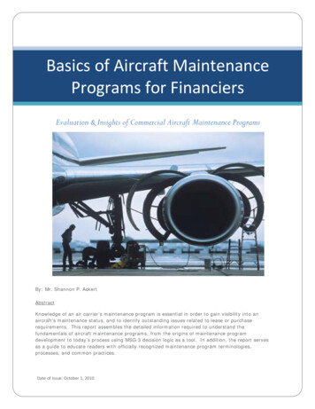
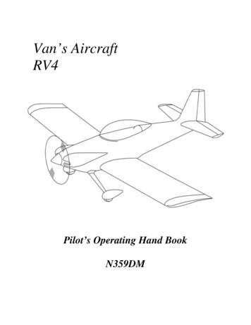
RV4RV-4 SPECIFICATIONSSpan23’0”Wing Loading (lbs/sq ft)13.64Length20’4”Power Loading (lbs.)9.375 (160 hp)Height5’5”Engine (hp)150-180Wing Area (sq. ft)110PropellerFixed or C/SEmpty Weight (lbs)93332Gross Weight (lbs)1500Fuel Capacity(US gallons)Baggage1100
TABLE OF CONTENTSSECTION1GENERAL2LIMITATIONS3EMERGENCY PROCEDURES (Stall & Spin recovery)4NORMAL PROCEDURES5PERFORMANCE6WEIGHT & BALANCE7SYSTEMS and OPERATION of SYSTEMS8GROUND HANDLING, SERVICE & MAINTENANCE9EQUIPMENT LISTING (Supplier listing)APPENDICIES1234Electrical DiagramsPerformance curvesWeight & BalanceMaintenance2
SECTION 1GENERAL1.1GeneralThis Pilot’s operating handbook is designed as an appropriate information manual and to provideinformation relevant to achieve maximum utilization of the Aircraft. It is not designed to be asubstitute for adequate and competent flying instruction and should not be used for operationalpurposes unless kept up to date.Assurance that the Aircraft is airworthy is the responsibility of the owner. The Pilot in commandis responsible for ensuring the Aircraft is safe for flight and for operating within the limitsdetailed in this handbook and as displayed on placards and instrument markings in the Aircraftand in accordance with current FAA regulations.1.2ENGINEEngine ManufacturerModel NumberRated HorsepowerRated Speed (rpm)Displacement (Cubic inch)Compression RatioType1.3LycomingE2D1502700 (Note Propeller limitation)3207.00:1Four cylinders, Direct driveHorizontally Opposed, Air CooledPROPELLERManufacturerModelNumber of bladesDiameterTypeLimitation1.4Catto6672366 INSFixed pitch3200 rpmFUELCapacityUseable FuelFuel Grade, Aviation32 Gal (US)30 Gal (US)100LL3
1.5OILOil CapacitySpecificationViscosity to Ambient Temp for starting: -8 Qts.Ref Lycoming ManualSINGLESAE 50SAE 40SAE 30SAE 20Above 60 F30 F to 90F0 F to 70 FBelow 10 F1.61.7MULTI - GRADESAE 40 or 50SAE 40SAE 40 or 20W-30SAE 20W-30WEIGHTSMaximum take off/landing weightMax Baggage Weight1550 lbs100 lbs (subject to Weight & Balance)Standard empty weight(Includes full oil)933 lbsMaximum Useful load (Subject toWeight & Balance)617 lbsSPECIFIC LOADINGSWing loadingPower loading14.09 lbs per sq ft10 lbs per hp4
SECTION 2LIMITATIONS2.01 Airspeed LimitationsVneVnoVaVfeINDICATED AIR SPEED212 mph185 Kts180 mph156 Kts135 mph115 KtsNever exceedNormal operations, smooth airDo not perform full or abruptControl movements above.Flap extension speed:20 deg flap40 deg (full) flap110 mph100 mph96 Kts87 KtsNOTE: Because of high ratio of top speed to stall speed and Maneuvering speed theAircraft is more susceptible to pilot induced overstresses than most other contemporaryaerobatic airplanes. THE PILOT CAN THEREFORE EASILY IMPOSE DESTRUCTIVELOADS ON THE AIRFRAME ABOVE THE RELATIVELY LOW MANEUVERINGSPEED. NOTE LIMITATIONS, EXERT CAUTION AND FLY ACCORDINGLY.2.02 Airspeed indicator MarkingsMARKINGINDICATED AIR SPEEDRed line (Never exceed)Black Line (Maneuvering speed max)Yellow (Caution - smooth air or light turbulence)Top Green Arc (max structural cruise)Bottom Green Arc (Flapless stall)Top White Arc (max speed full flap)Bottom White Arc (Stall full flap)212 mph134 mph180/210 mph180 mph54 mph100 mph50 mph2.03 Power plant limitationsBased on installed engine Lycoming O320 E2DMaximum Horse PowerMax Engine SpeedOil TemperatureMaximumDesiredOil PressureMin.MaxOil Sump Capacity MaxMin51502700 rpm245 Deg. F180 Deg. F25 psi90 psi8 US qts.2 US qts185 Kts115 Kts155/184 Kts155 Kts48 Kts87 Kts44 Kts
Fuel PressureMin (red line)DesiredMax (red line)0.5 psi3 psi8 psiFuel Grade (minimum octane)80 RedPropellerMax RPM3200 rpmOperating Approved Cylinder Head Temperature (CHT)High performance cruiseEconomy cruiseMin for maximum life435 Deg. F400 Deg. F150 Deg. FMax cooling target on decent 50 Deg F/min to avoid shock cooling, preferably 25 Deg F/min.2.04 Engine instrument markingsTachometerNormal operating range. Green ArcRed Line (Max Continuous Power)500/2700 rpm2700 rpmOil TemperatureGreen Arc Normal rangeRed line Max75 to 245 Deg. F245 Deg. FOil PressureGreen Arc Normal rangeYellow Arc Caution (Idle)Red line (Minimum)Red line (Max)60 to 90 psi25 to 60 psi25 psi90 psiFuel PressureGreen Arc Normal rangeRed line (Minimum)Red line (Maximum)0.5 to 8 psi0.5 psi8 psiCylinder Head TemperatureRed lineGreen Ark Normal range6450 Deg. F300 to 450 Deg. F
2.05 Weight LimitationsGross Weight (Subject to Weight & Balance)1550 lbsAerobatic Gross weight. With aft CG 27.5%Of cord or (15.9” aft of leading edge)1375 lbsMaximum baggage (Subject to Weight & Balance) 100 lbs2.06 Center of Gravity LimitsDesign CG range is:Forward limit 15% Wing chord 8.7" from L.E. 68.7" aft of datumRearward limit 30% Wing chord 17.4" from L.E. 77.4" aft of datumNote: datum 60" forward of L.E. (leading edge of wing)2.07 Maneuvering LimitsRefer to Maneuvering speed and weight and balance limitations when contemplating aerobatics.This is highest speed at which full and abrupt control can be applied without exceeding designstrength. This is not highest permissible aerobatic entry speed, for any speed above maneuveringspeed control inputs must be limited to less than full.Due to wide speed range entry speeds for some maneuvers can vary over a wide range. Forvertical maneuvers (i.e. Loops, Immelmann turns and horizontal eights) entry speed has aninverse relationship to G forces required to complete the maneuver. An entry speed at lowerspeeds will require a higher G pull up than for entry near top end of speed range. Note that dueto relatively light control stick forces and high aerodynamic cleanliness excessive speedbuild up can occur very quickly, and particularly in a dive. Due to light control forces andaerodynamic cleanliness the RV 4 is a Pilot limited aircraft - it is the pilot’s responsibilitynot to overstress the aircraft. Following are guidelines only as starting point for aerobatictesting.Loops, Horizontal EightsImmelmann turnsAileron Rolls, Barrel rollsSnap RollsVertical rollsSplit -S140-190 mph150-190 mph120-190 mph80-110 mph180-190 mph100-110 mph7120-165 Kts130-165 Kts105-165 Kts70-95 Kts155-165 Kts87-95 Kts
2.08 Flight Load FactorsThe structure has been designed to withstand aerobatic load of 6 G positive and 3 G negative(plus 50% safety factor on design limit of negative 6 G) at aerobatic gross weight of 1375 lbs.This is the maximum load the airframe structure is designed to withstand indefinitely. Thecalculated breaking strength is 9G at which it will withstand load for 3 seconds (assuming noairframe deterioration, fatigue, material flaws or construction errors). Approaching this 9G loadcould permanently weaken the structure even if failure does not occur.2.09 PlacardsLocationInstrument PanelPilot Compartment, LHSPassengerCompartment, LHSPassengerCompartment, RHSBaggageCompartment, RHSInstrument Panel RHSPlacardRemarksSOLO – Front Seat OnlyAEROBATIC LIMITATIONSRefer to the Operating limitation foraerobatic maneuvers permitted inthis aircraftThis Aircraft is amateur built andThis aircraft is built todoes not comply with federal safetya higher standardsregulations for standard aircraftMaximumCapacityofthiscompartment 240 lbs. Check Weightand BalanceMaximumCapacityofthiscompartment 100 lbs. Check Weightand BalanceDo not solely rely on fuel levelinstrument to determent the fuellevels in the aircraft2.10 Types of Approved OperationThe FAA approves this aircraft for Day / Night V.F.R. operation8
SECTION 3EMERGENCY PROCEDURES(Stall and Spin recovery)3.01 GeneralRecommended procedures for dealing with various types of emergency and critical situations aredetailed in this section. They are suggested as the best course of action based on the aircraftstructure, equipment and systems configuration. They are however not a substitute for soundjudgment and common sense and are NOT intended to replace pilot training. Pilots shouldfamiliarize themselves with the procedures and be prepared to take appropriate action should anemergency arise.3.02 Emergency Procedures ChecklistCommitted to Power off landingFuel.OFFMixture.IDLE CUT OFFFuel Pump.OFFThrottle.CLOSEDMagnetos.OFFCanopy Catch. RELEASEHarnesses.TIGHTRadio. MAYDAY CALLMasters.OFFEngine RoughCarb Heat.ONPrimer.LOCKEDIf rough after 1 Min.Carb Heat.OFFMixture. ADJUST SMOOTHFuel Pump .ONFuel.Change TanksMags.L then R & BOTHRun on Best settingNearest suitable landingPrepare power off landingOil Pressure lossLand ASAP and investigatePrepare Power off LandingFuel Pressure LossFuel Pump.ONFuel.Change tanks if fuelledHigh Oil TemperatureLand ASAP and investigatePrepare Power off LandingPower loss on takeoffSufficient Runway AheadIF AIRBORNE DON’T STALLThrottle.CLOSEStop Straight AheadInsufficient Runway AheadIF AIRBORNE DON’T STALLThrottle.CLOSEBrakes.as requiredMixture.IDLE CUT OFFFuel.SELECT OFFFuel Pump.OFFMagnetos.OFFMasters.OFFFlaps .AS REQUIREDManeuver to land. DON’T STALLPower loss in flightTrim. Best Glide 71ktsCarb Heat.ONFuel Pump.ONPrimer.CHECK LOCKEDMixture.RICHFuel Selector.To FULLEST TANKMagnetos.ONEngine Gauges.CHECKIf Power not restoredMags L then R & BOTHThrottle & Mixture:TRY DIFFERENT SETTINGS9
Check Circuit breakersMasters OFF 1 Second then ON(Resets voltage regulator)IF no outputAlternator switch.OFFReduce electrical loadLand ASAPEngine fire during StartStarter.CRANK ENGINEMixture.IDLE CUT OFFThrottle.OPENFuel pump.OFFFuel Selector.OFFAdvise ATC if continuesMasters.OFFAbandon if fire continuesRadio FailureRadio.Check ONRadio Master.Check ONVolume.Turned UPSQUELCH.Turned UPHeadset.Plugged INCircuit Breaker.CheckFrequency.SelectedIF FAILURE CONFIRMEDTransponder.SET 7600Transmit (Rx may have failed)Land ASAPConsider Emergency Radio if AvailableEngine Fire in FlightFuel Selector.OFFThrottle.CLOSEDMixture.IDLE CUT OFFFuel PUMP.OFFCabin Heat.OFFMagnetos.OFFPrepare emergency LandElectrical Fire (Smoke in Cabin)Masters.OFFCabin Heat.OFFUSE EXTINGUISHER WITH CAUTIONOpen Air vents to clear CabinElectrical switches.OFFMasters.ONIsolate faulty circuitReinstate Essential servicesLand ASAPBrake Failure on GroundThrottle.CLOSESTEER TO GRASS AREA INTO WINDMixture .IDLE CUT OFFMagnetos.OFFAdvise ATCShut Down ChecksCabin FireAir Vents.CLOSEUSE EXTINGUISHER WITH CAUTIONOpen Air vents to clear CabinLand ASAPBrake failure after touchdownOvershoot ActionRadios .GIVE DETAILSLand on SAFE GRASS LONGESTRUNWAY INTO WINDShut Down ChecksAwait assistanceAlternator FailureVerify failure from instrumentsReduce electrical load10
Ditching in water - Life jackets to be worn for Sea CrossingHarnesses.TIGHTCabin Latch.UNLOCK. NOT OPENFinal Approach. Master OFFNO FLAP SELECTED (Pitches DOWN)HOLD OFF “SPLASH” TAIL DOWNDitching ProcedureAlways Check DIRECTION OF SWELLand WINDTurn towards LAND/SHIPPINGTrim .BEST GLIDE 71 KtsPlan landing.ALONG SWELLORNo Swell.INTO WINDCheck Failure.ATTEMPT CORRECTIONRadio.MAYDAYEngine.Shut Down ProcedureLeaving AircraftSeat Belts.ReleaseCanopy.OpenExit onto WingInflate Life Jacket3.03Notes on Emergency procedures3.03.01Engine power loss during takes offAction depends on circumstances. If sufficient runway remains then land straight ahead. Ifinsufficient runway remains, maintain a safe airspeed and make only shallow turns to avoidobstructions. Use of flap depends on circumstances; they would normally be fully extended forlanding. With sufficient altitude and safe speed established engine restart procedure can beinitiated. Fuel pump on with mixture rich, carburetor heat should be on and the primer checked toensure it is locked. Engine failure due to fuel exhaustion may require up to 10 seconds afterswitching tanks.3.03.02Engine power loss in flightComplete power loss is usually due to fuel interruption, if this is so power will be restored whenfuel flow is itself restored. The first action is to trim for best glide 71 KIAS and establish if thereis time to attempt restart or immediately prepare for an emergency “Power Off” landing.Restart procedure is to switch to the other tank (provided it is fuelled), turn on the fuel pump andmove mixture to rich and the carburetor heat on. Check engine gauges for an indication of causeand if no fuel pressure is indicated change tank selection. Primer should be locked. When poweris restored move carburetor heat to cold and turn fuel pump off.If engine still fails to restart and time permits turn the ignition to “L” then “R” then backs to both.Try moving the throttle and/or mixture to different settings. This may restore power if mixture istoo rich or too lean or if there is a partial fuel blockage. Try the other tank; water in the fuel maytake time to clear the system. Allowing the engine to windmill may restore power. If failure isdue to water then fuel pressure will be normal. Empty fuel lines may take ten seconds to refill.Power Off landing is covered in section 3.02.0311
3.03.03Power Off LandingThe initial action is ALWAYS TRIM FOR BEST GLIDE 71 Kts IAS if power restorationmeasures are ineffective and time allows check for airports/strips available and notify ofproblem/intent if possible.Identify a suitable field, planning an into wind landing. Try to be 1000 ft at the end of thedownwind leg to make a normal landing. Aim initially for the center of the field (drag with awind milling propeller will be higher than you are used to) and only lower final stages of flapwhen you judge you can reach the field. Plan for slowest short field landing but do not stall.When committed to landing close throttle, turn off masters and ignition switches. Turn fuelselector to off and move mixture to idle cut off. Seat belts should be tight and touchdown at theslowest speed possible.3.03.04Engine Fire during StartThese are usually due to over priming. The first attempt to extinguish the fire is to draw theexcess fuel back into the induction system. If the engine has started continue to operate to pull thefire into the engine. If the engine is not operating move mixture to idle cut off, open the throttleand crank the engine to draw fire into the engine.If in either case the fire continues for more than a few seconds it should be extinguished byexternal means. Fuel selector should be off and mixture at idle cut off.3.03.05Fire in FlightEngine fire in flight is extremely rare. If it is present switch fuel selector off and close throttle.Mixture should be at idle cut off and booster pump off. Close heater and subject to radiorequirements turn masters off. Proceed with Power off Landing.Cabin fire is identified through smell and smoke - be sure it is not from outside! It is essential thesource be identified through instrument readings, nature of smoke or system failure. If anelectrical fire is indicated masters should be turned off, cabin heat turned off and vents open. Fireextinguisher should be used with caution. Proceed with Power off landing procedure.3.03.06Oil Pressure LossThis may be partial or complete, or it may be a gauge malfunction. Note the oil pressure gauge iselectrical.A partial loss of oil pressure is usually a regulation problem. A landing should be made as soonas possible.A complete loss of pressure may signify oil exhaustion (or faulty gauge). Proceed to nearestairport/airfield and be prepared for a forced landing. The engine may stop suddenly. Maintainaltitude and do not change power settings unnecessarily, as this may hasten power loss.12
An off airfield landing while power is available should be considered especially in the presenceof additional indicators e.g., rise in engine CHT or oil temperature, oil and/or smoke apparent.3.03.07Fuel Pressure lossIf fuel pressure falls, turn on the electric pump and check selector is on a full tank. If the problemremains land as soon as possible and check system.3.03.08High Oil TemperatureHigh oil temperature may be due to a low oil level, obstruction in oil cooler (internal or external),damaged baffle seals, a defective gauge (on this aircraft it is an electrical gauge), or other causes.A steady rise is a particular sign of trouble.Always land as soon as possible at an appropriate airport/airfield and investigate and be preparedfor an engine failure. Watch the oil pressure and CHT (Cylinder Head Temperature) gauge toidentify impending failure.3.03.09Alternator FailureThis is identified from progressive voltage drop (low voltage warning light and voltmeter).Initially check operation by actuating a high load item (e.g. landing lightReduce electrical load as much as possible and check circuit breakers.Attempt to reset by turning off the alternator switch for one second and then back on again. If thecause was a momentary over voltage (16.5V ) this will return the system to normal working.If the indications are that there is zero alternator output turn Alternator switch off, use onlyminimum electrical load and land as soon a practicable. Note that the flaps are electrically drivenso prepare for a flapless approach.3.03.10Engine RoughnessThis is usually due to carburetor icing indicated by a drop in RPM and may be accompanied byslight loss of airspeed and/or altitude. If too much ice accumulates restoration of full power maynot be possible, therefore prompt action is required.Turn carburetor heat on. RPM will decrease slightly and roughness increases. Wait for a decreasein engine roughens or increase in RPM, indicating ice removal. If no change in approximatelyone minute return carburetor heat to off.Partial carburetor heat may be worse than no heat as it may melt part of the ice, which willrefreeze in the intake system. Therefore always use full heat and when ice is removed return tofull cold position.13
If engine is still rough adjust mixture for maximum smoothness. Engine will run rough if too richor lean. Switch fuel pump on and try other tank to check fuel contamination. Check enginegauges for normality and react accordingly. Move magneto switches to “L” then “R” and both. Ifoperation is satisfactory on either magneto proceed at reduced power, with mixture rich, tonearest airport/airfield.3.04Stall and Spin RecoveryThe following has been taken from information provided by Vans Aircraft Inc, which it is basedon their testing of RV4 aircraft. Characteristics of different aircraft are different; the informationshould be taken as a guide only and not as specific to this aircraft.3.04.01Stalls (Notes from testing section of Vans assembly manual for aircraft)Indicated stalling speed of 38 mph can possibly be 50 mph or more. However the readings arerelative and you can believe the gauge will indicate the same speed consistently, if the stall isapproached at the same rate every time.Except for accelerated stalls and secondary stalls, approach each slowly while keeping the nosefrom turning with the rudder. Allow the speed to bleed off until you feel a slight buffet. Note theairspeed and recover with a smooth forward movement of the stick as power is added. Maybesimply relieving backpressure on the stick when the stall occurs will be sufficient for yourairplane. Stalls entered from steep bank or climb will require more aggressive recovery controlapplication. Remember the RV4 has light elevator forces, and over control can easily occur,and secondary stalls encountered.3.04.02Spins & Spin RecoveryVans aircraft does not consider spins to be a recreational aerobatic maneuver and does notrecommend that they be casually undertaken in the aircraft.Intentional spin entry should be initiated from a power off stall with full rudder in one directionand full elevator following the initial break. Typical spin behavior for an RV is that the controlpressures are released immediately following spin entry, recovery will be automatic and almostimmediate-no more than ½ spin revolution. If spin rotation is held for approximately one fullrevolution, recovery can be accomplished quickly through application of anti-spin control(opposite rudder, stick centered).If pro-spin controls are held until two full revolution have beencompleted, the spin will be fully developed. Recovery techniques will vary.The most effective technique is as follows:1. Power off2. Elevator centered.(or stick free)3. Full opposite rudder.4. Recover from dive as soon as rotation stops.Recovery time (time to stop rotation) will vary depending on C.G. position and other factors.14
Step#2 is best accomplished “hands-on stick” rather than stick free because while in spinrotation, the outside aileron will sometimes float up, thus driving the stick out of center.Good spin recovery is evident in the first two rotations. Simply releasing the controls during thefirst rotation stopped the spin, and opposite rudder and forward stick caused a quick recoveryduring the second rotation. After two turns, the rotation rate will increase and stabilized between3 and 4 turns with a high rate of rotation of about 180 degrees/second. Once past approximately 2spin rotations the spin has stabilized and if the controls are freed, the RV4 will continue spinninguntil anti-rotation control inputs are applied. The recovery procedure consists of the following1. Power to idle2. Apply full opposite rudder,(opposite the direction of rotation)3. Center the ailerons and elevator (because of up elevator float,( Forward stick pressure isneeded to center the elevators.)4. Hold the above control positions until rotation stops, then use elevator to recover to levelflight. 1 ¼ to 1 ¾ rotations are usually required for rotation to stop.15
SECTION 4NORMAL PROCEDURES4.01GeneralPilots should familiarize themselves with the procedures in this section to become proficient withthe normal safe operation of the aircraft4.02 Airspeeds for safe operationVyVxVaVsoVsVfeBest rate of climb speedBest angle of climb speedBest glide angleTurbulent air operating speedStall full flapStall flaplessMaximum full flap speedLanding Final approach speed (full 40 deg flap)Demonstrated crosswind velocityTake off rotate speedDemonstrated unstuck speed78 mph68 Kts82 mph71 Kts82 mph71 Kts132 mph115 Kts56 mph49 Kts60 mph52 Kts IAS100 mph87 Kts70 mph60 Kts(Note pitot error)to be established67 mph58 Kts(Based on Vs 11mph)60 Kts IAS4.03 Engine Operating ConditionsRPM HPNormal RatedPerformance Cruise (75%)Economy Cruise (65%)2700 1502450 1202350 104Fuel Cons.Gal/Hr13.48.47.3Max Oil Cons. Max.CHTQts/Hr0.68500 Deg.F0.38500 Deg.F0.33500 Deg.F4.04 Normal procedures check listEngine is equipped with electronic ignition, please read the P-Mag operation Notesbefore starting the engine.16
P-Mag Operating NotesStarting- To start the engine, simply turn on the 12 volt power to the ignition(The master power switch) Turn on the 2 switch breakers right of the start switch.Then start the engine with the start switch. Start mode is automatically sensed by the P-Magand provides multiple strikes to each cylinder.Stopping the engine – CAUTION P-Mag models are similar to magnetos in that the ignitionkill switch (or mixture control) is the only way to stop the ignition once the engine is started.Powering Down – With all P-Mag models, use your main power switch breakers to powerdown the ignitions. The ignition OFF switch (p-lead) only tells the P-Mag to stop generatingspark. It does NOT cut power to the ignition. If you leave the aircraft with the P-Mags poweron, they will draw down your battery over time.P-Mag Alternator Check – You can check the internal alternator operation on the P-Magduring run-up (900 rpm) by switching to the P-Mag ignition and cutting 12 volt power(Switch Breaker). If built in alternator is working, the engine will continue to run.If it is not working, the engine will quit.17
PREFLIGHT CHECKEXTERNAL CHECKSSTARTINGAll switches.OFFExterior .check for damageFlap pushrod ends . wear/securityRear Empennage fairing. Secure round elevatorControl surfaces ck. interferenceHinges interference/hinges .okTanks. caps secure & quantityTank drains. DrainFuel vents. ClearTires. Check okPitot tube. ClearCanopy . CleanProp & Spinner .okOil. check levelDipstick .secureCowl .SecureAir inlets .ClearStatic port. ClearMaster . ONFlap.ExtendNav lights.CHECKStrobe.CHECKFuel gauges/Quantity.CHECKMaster .OFFStart (10 Sec Max Crank time)1200 rpm setAlternator onCheck: Oil pressure (max 90 min 60 psi)Fuel pressure (max 8 min 0.5)Volt meterMagnetosStrobe onAI risingRadio Master on & set radiosTAXYINGBrakes checkInstruments checkPOWER CHECKBrakes onChange tanks1800 rpm setCheck: Carb heatMag drop (Drop less than 175 rpmNot greater 50 rpm between mags)VoltsOil tempCHT (all above 150 Deg.F)Idle @ 500/700INTERNAL CHECKSCanopy latchedControls Full & FreeMaster onFlap setTrims cycle & checkFuel select to fullest tankPump on check pressurePump offCarb heat setMixture richThrottle set (1/4” travel open)Prime (3 strokes max)PRE TAKE OFFTrim setMixture richMagnetos both onCarb air coldFuel pump onPrimer lockedFuel statusFlaps as requiredAltimeter setEngine instruments checkCanopy closed and lockedHarnesses secureCollision lights onControls full and free18
POST FLIGHT CHECKAFTER LANDING CHECKS1. Unnecessary electrics off2 .Flaps up if appropriate3. Carb air coldCLIMB CHECKSI Icing/IDENTP powerA AltimeterSHUTDOWN CHECKS1 Park brake on2 1200 RPM set3 Magnetos check4 Radios (MASTER) off5 Electrics off6 Mixture cut off7 Magneto Switch off8 Master switches off9 Fuels offTOP OF CLIMBF Fuel pump off/Mix setA Altimeter setI Indent Nav. aidsL Landing light offANDP PowerA AltimeterT TransmitTURN CHECKSS StopwatchT Turn/trackA Altimeter setR R/T reportR Radio/nav setLANDING CHECKSB BrakesM Mixture richC Carb air HotF Fuel tank & PumpH Harnesses/ArticlesC Carb air ColdE Engine T's & P'sORT TimeT TurnT TalkHASELL CHECKH Height sufficientA Airframe/flapsS Security/harnessesE Engine T & P, MixtureL LocationL LookoutFEMDO ROUTE CHECKF FuelE EngineM MixtureD D/I setO Orientation.FIELD APPROACHF Fuel tankR Radio Freq. /volE Engine T's & P'sCarb air, MixtureD D.I setA Altimeter setDESCEND CHECKSS Sector safetyA AltitudeS SpeedAFTER TAKE OFF CHECKSG (Gear up)F Flaps upH Heading/speed check19
SECTION 5PERFORMANCE5.01GENERALAircraft performance will be specific to a particular airplane. Whilst experience has showthat Vans published test data is close to that of other similar aircraft, differences in buildstandards and equipment fitted inevitably mean individual evaluation is required.In this section (Prov) against a performance characteristic means it has been obtained frompublished data and the characteristic for this aircraft has yet to be established. In somecases data is not currently available.5.02Airspeed CalibrationAir speed systems, particularly in home build aircraft are usually inaccurate. The system as fittedhas proven to be reasonably accurate.5.03Stall SpeedsStall speed with full 40 deg flapStall speed flapless5.045.0556 mph 49 Kts60 mph 52 Kts IASClimb PerformanceBest Climb angle 1230 lbs GrossBest Climb angle 1500 lbs Gross78 mph 68 Kts82 mph 71 KtsBest rate of climb 1230 lbs GrossBest rate of climb 1500 lbs Gross110mph 96 Kts120mph 105 KtsGliding RangePERFORMANCE GRAPHS TO BE ESTABLISHEDBest Glide angle? Lbs Gross2082 mph 71 Kts
5.06Take off & Landing PerformancePERFORMANCE GRAPHS TO BE ESTABLISHEDVans quoted figures: Take off distanceLanding distance5.08300/535 ft300/500 ftEngine PerformancePERFORMANCE GRAPHS TO BE ESTABLISHEDTop speedCruise 75% @ 8000 ft mslCruise 55% @ 8000 ft mslRV-4 Solo Weight (1160 lbs)Engine (hp)150160Top 5%@8000’)Stall Speed4848Takeoff325300Distance (ft)Landing300300Distance (ft)Rate of Climb 1850 2050(fpm)Ceiling (ft)21,70 24,0000Speed Ratio4.2:1 4.27:1201 mph 174 Kts189 mph 164 Kts170 mph 148 Kts180213201RV-4 Gross Weight (1500 lbs)Engine (hp)150Top Speed200Cruise (75%@8000’)188160204192180212200182Cruise (55%@8000’)17017318048260Stall SpeedTakeoff Distance (ft)544755445054400300Landing Distance (ft)4254254252450Rate of Climb (fpm)1500165019502
Assurance that the Aircraft is airworthy is the responsibility of the owner. The Pilot in command is responsible for ensuring the Aircraft is safe for flight and for operating within the limits detailed in this handbook and as displayed on placards and instrument markings in the Aircraft and in accordance with current FAA regulations. 1.2 ENGINE