Transcription
CdSxTe1-x Alloying inCdS/CdTe Solar CellsPreprintJoel N. Duenow, Ramesh G. Dhere,Helio R. Moutinho, Bobby To, Joel W. Pankow,Darius Kuciauskas, and Timothy A. GessertPresented at the 2011 Materials Research Society Spring MeetingSan Francisco, CaliforniaApril 25–29, 2011NREL is a national laboratory of the U.S. Department of Energy, Office of EnergyEfficiency & Renewable Energy, operated by the Alliance for Sustainable Energy, LLC.Conference PaperNREL/CP-5200-50156May 2011Contract No. DE-AC36-08GO28308
NOTICEThe submitted manuscript has been offered by an employee of the Alliance for Sustainable Energy, LLC(Alliance), a contractor of the US Government under Contract No. DE-AC36-08GO28308. Accordingly, the USGovernment and Alliance retain a nonexclusive royalty-free license to publish or reproduce the published form ofthis contribution, or allow others to do so, for US Government purposes.This report was prepared as an account of work sponsored by an agency of the United States government.Neither the United States government nor any agency thereof, nor any of their employees, makes any warranty,express or implied, or assumes any legal liability or responsibility for the accuracy, completeness, or usefulness ofany information, apparatus, product, or process disclosed, or represents that its use would not infringe privatelyowned rights. Reference herein to any specific commercial product, process, or service by trade name,trademark, manufacturer, or otherwise does not necessarily constitute or imply its endorsement, recommendation,or favoring by the United States government or any agency thereof. The views and opinions of authorsexpressed herein do not necessarily state or reflect those of the United States government or any agency thereof.Available electronically at http://www.osti.gov/bridgeAvailable for a processing fee to U.S. Department of Energyand its contractors, in paper, from:U.S. Department of EnergyOffice of Scientific and Technical InformationP.O. Box 62Oak Ridge, TN 37831-0062phone: 865.576.8401fax: 865.576.5728email: mailto:reports@adonis.osti.govAvailable for sale to the public, in paper, from:U.S. Department of CommerceNational Technical Information Service5285 Port Royal RoadSpringfield, VA 22161phone: 800.553.6847fax: 703.605.6900email: orders@ntis.fedworld.govonline ordering: http://www.ntis.gov/help/ordermethods.aspxCover Photos: (left to right) PIX 16416, PIX 17423, PIX 16560, PIX 17613, PIX 17436, PIX 17721Printed on paper containing at least 50% wastepaper, including 10% post consumer waste.
CdSxTe1-x Alloying in CdS/CdTe Solar CellsJoel N. Duenow, Ramesh G. Dhere, Helio R. Moutinho, Bobby To, Joel W. Pankow, DariusKuciauskas, and Timothy A. GessertNational Renewable Energy Laboratory, 1617 Cole Blvd., Golden, CO 80401ABSTRACTA CdSxTe1-x layer forms by interdiffusion of CdS and CdTe during the fabrication of thinfilm CdTe photovoltaic (PV) devices. The CdSxTe1-x layer is thought to be important because itrelieves strain at the CdS/CdTe interface that would otherwise exist due to the 10% latticemismatch between these two materials. Our previous work [1] has indicated that the electricaljunction is located in this interdiffused CdSxTe1-x region. Further understanding, however, isessential to predict the role of this CdSxTe1-x layer in the operation of CdS/CdTe devices. In thisstudy, CdSxTe1-x alloy films were deposited by RF magnetron sputtering and co-evaporationfrom CdTe and CdS sources. Both radio-frequency-magnetron-sputtered and co-evaporatedCdSxTe1-x films of lower S content (x 0.3) have a cubic zincblende (ZB) structure akin to CdTe,while those of higher S content have a hexagonal wurtzite (WZ) structure like that of CdS. Filmsbecome less preferentially oriented as a result of a CdCl2 heat treatment at 400 C for 5 min.Films sputtered in a 1% O2/Ar ambient are amorphous as deposited, but show CdTe ZB, CdSWZ, and CdTe oxide phases after a CdCl2 heat treatment (HT). Films sputtered in O2 partialpressure have a much wider bandgap (BG) than expected. This may be explained bynanocrystalline size effects seen previously [2] for sputtered oxygenated CdS (CdS:O) films.INTRODUCTIONA CdSxTe1-x layer forms by interdiffusion of CdS and CdTe during the fabrication of thinfilm CdTe PV devices in the standard superstrate configuration. High-temperature processingsteps such as the close-spaced sublimation of CdTe and the post-deposition CdCl2 HT contributeto formation of this alloy [1]. The CdSxTe1-x layer is thought to be important in fabricating highperformance CdTe devices because it relieves strain at the CdS/CdTe interface that wouldotherwise exist due to the large lattice mismatch ( 10%) between these two materials. Ourprevious work indicated that the electrical junction is located in this interdiffused CdSxTe1-xregion between a structurally compatible Te-rich n-type CdSxTe1-x alloy and p-type CdTe [1,3].The CdSxTe1-x alloy has been found to follow Vegard’s Law [4], such that lattice parametervalues obtained from X-ray diffraction measurements can be used to calculate the mole fraction(x) for different phases of CdSxTe1-x. The BG of CdSxTe1-x has been described as a quadraticfunction of x [5], with values decreasing below the CdTe BG value of 1.5 eV, to as low as 1.41eV at x 0.3, before increasing at higher x values. The alloy system also exhibits a miscibility gap(two-phase region) in which both a CdTe-rich ZB phase and CdS-rich WZ phase may be presentsimultaneously at equilibrium. The composition of each phase in the two-phase region is thesame as in the corresponding single-phase regions at the edges of the miscibility gap, with therelative quantity of each phase present varying with x [6]. Single-phase films, however, havebeen grown within the miscibility gap, implying non-equilibrium growth methods were used.The phases generally separated after a CdCl2 HT [6-8]. We found similar behavior in this study.1
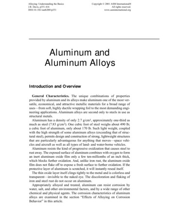
Further understanding of CdSxTe1-x alloys is essential to predict the role of the CdSxTe1-xlayer in the operation of CdS/CdTe devices. In this study, we investigate this alloy layer bydepositing CdSxTe1-x films using two methods.EXPERIMENTAL DETAILSWe deposited CdSxTe1-x films by radio frequency (RF) magnetron sputtering using targets ofthree compositions: 10/90, 25/75, and 60/40 wt.% CdS/CdTe. Films were deposited at roomtemperature (RT; no intentional heating) and at 300 C. Because little difference was seenbetween films grown at RT and at 300 C, only the 300 C results are presented here. In addition,two deposition ambients were used—100% Ar and 1% O2/Ar. The ratio was measured using anion gauge. Films were also deposited by co-evaporation from CdTe and CdS sources usingRadak II effusion cells. The geometry of the co-evaporation system enabled us to obtain a rangeof compositions during a single deposition. The films were deposited onto three differentsubstrates—Corning 7059 glass, Corning 7059 glass/450 nm SnO2:F/150 nm SnO2, and Corning7059 glass/SnO2:F/SnO2/125 nm sputtered CdS:O—to be amenable to the different types ofcharacterization performed on the films. Reflectance and transmittance measurements wereperformed using a Cary 6000i UV-Vis-NIR spectrophotometer. Electron probe microanalysis(EPMA) was performed using a beam energy of 5 kV to obtain film composition. X-raydiffraction (XRD; Rigaku Ultima IV) θ-2θ measurements were performed using Cu Kα radiationto examine the structure of the CdSxTe1-x films. Electron backscatter diffraction (EBSD; FEIFEG SEM Nova 630 NanoSEM with an EDAX Pegasus/Hikari A40 EDS/EBSD system)measurements were performed to examine grain orientation and size for selected films.RESULTS AND DISCUSSIONComposition of the 150-nm-thick sputtered CdSxTe1-x alloy films was measured usingEPMA (Fig. 1, left panel). Films were grown in 100% Ar and 1% O2/Ar both before and after a5 min. vapor CdCl2 HT at 400 C. Films grown from the 10/90 wt.% CdS/CdTe target show littlecompositional change between the different deposition ambients and after the CdCl2 HT. FilmsFig. 1. Measured x values for sputtered (left) and evaporated (right) CdSxTe1-x films fromEPMA. Dashed lines in the left plot indicate the manufacturer’s stated target composition.Evaporated films were measured at four positions because of the inherent composition gradientacross the substrate due to the deposition system geometry.2
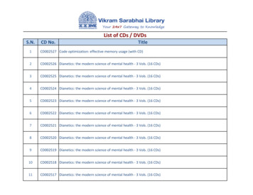
grown from the 25/75 and 60/40 wt.% CdS/CdTe targets in the 100% Ar ambient display a slightenrichment in S (or, equivalently, a loss of Te) after the CdCl2 HT. All films appear S-deficient,however, compared to the manufacturer’s stated target composition. This may be due todifferences in sticking coefficient on the substrate of the S and Te species. Two 300-nm-thickevaporated CdSxTe1-x films (Fig. 1, right panel) were deposited using different combinations ofCdS and CdTe effusion cell temperatures. The as-deposited films (solid lines) show the expectedgradient in x across the substrate. The evaporated films also show a significant relativeenhancement in S (or loss of Te) after the CdCl2 HT.CdSxTe1-x alloy film structure was investigated using XRD. θ-2θ scans of films grown fromthe 10/90 wt.% CdS/CdTe target in the 100% Ar and 1% O2/Ar ambients both before and after aCdCl2 HT are shown in Fig. 2. Films examined using XRD were deposited on Corning 7059glass/450 nm SnO2:F/150 nm SnO2/125 nm sputtered CdS:O substrates similar to those used forCdTe PV devices. Tetragonal SnO2, cubic ZB CdTe, and hexagonal WZ CdS peaks areindicated. The as-deposited film grown in 100% Ar shows one prominent peak, CdTe ZB (111).Other peaks in this spectrum are due to the SnO2 films on the substrate. After a CdCl2 HT isperformed on this film, the CdTe ZB (111) peak decreases in intensity, while small CdTe ZB(220) and (311) peaks, and CdS WZ (100), (002), and (101) peaks, appear. This behaviorindicates a decrease in preferential orientation after the CdCl2 HT. The film grown in 1% O2/Aris amorphous as deposited. After the CdCl2 HT, however, many CdTe ZB and CdS WZ phasesappear, in addition to prominent CdTe oxide phases (e.g. CdTeO3, CdTe2O5). Further work isrequired to identify which oxide phases are dominant. A summary of XRD results for thesputtered films is shown in Table 1. Films grown in 100% Ar from the 60/40 wt.% CdS/CdTetarget contain only CdS WZ phases, both before and after the CdCl2 HT, while films of higherCdTe content in this ambient show both CdTe ZB and CdS WZ phases. All films grown in 1%O2/Ar are amorphous as deposited. The CdTe oxide peaks observed after the CdCl2 HT are muchless intense for the 25/75 and 60/40 wt.% CdS/CdTe films than for the 10/90 wt.% film.XRD measurements were also performed on evaporated CdSxTe1-x alloy films both beforeand after a CdCl2 HT at 390 C. Measurements were performed at several points on the filmbecause of the composition gradient. The CdTe ZB (111) peak was observed to shift to anintermediate position between it and the adjacent CdS WZ (100) peak as the S content increased.Fig. 2. XRD scans for sputtered CdSxTe1-x films grown from the 10/90 wt.% CdS/CdTe target.Growth ambient and post-deposition treatment are shown on the plot. Peak positions from thepowder diffraction files corresponding to these materials are shown at the bottom (withcorresponding file numbers shown in the upper right).3
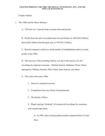
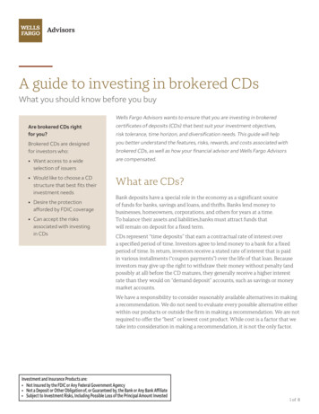
Table 1. Phases present in sputtered CdSxTe1-x films grown in 100% Ar and 1% O2/Ar beforeand after a CdCl2 HT.100% Ar1% O2/ArWt.% CdS/CdTeAs Dep.Aft. CdCl2As Dep.Aft. CdCl210/90CdTe ZBCdTe ZBCdS WZAmorphous25/75CdTe ZBMinor CdS WZCdTe ZBCdS WZAmorphous60/40CdS WZCdS WZAmorphousCdTe ZBCdS WZStrong Oxide PhasesCdTe ZBCdS WZOxide PhasesCdS WZOxide PhasesAfter the CdCl2 HT, the CdTe ZB (111) peak shifts toward its expected position, while otherCdTe ZB and CdS WZ phases appear, indicating a decrease in film preferential orientation.These data are summarized in Table 2. The separation of the CdTe ZB (111) and CdS WZ (100)peaks suggests that phase separation occurs as a result of the CdCl2 HT.Analysis was performed to extract the lattice constants and mole fraction of the CdTe ZBphase from the XRD data. The lattice constant aCubic was determined usinga Cubic d h 2 k2 l 2 , where d λa (2sin θ ) is calculated from the measured 2θ peak position,λα 1.540562 Å is the wavelength of the Cu Kα radiation, and h, k, and l are the Miller indices forthe diffraction peak. When multiple CdTe ZB peaks were present, the aCubic values were plottedas a function of the Nelson-Riley-Sinclair-Taylor (NRST) function [6],1 cos2 θ cos2 θ NRST .2 sinθθ Fitting a line to these points enabled a lattice constant of greater precision to be found byextrapolating to normal incidence at NRST 0 [6]. Vegard’s law, which applies to the CdTe-CdSalloy system [4], was then used to determine the mole fraction, x, for the cubic ZB phase: a CdTea.x CdSx Te1 x ( Cubic )a CdS a CdTeFor cubic phases, aCdTe 6.481 Å and aCdS 5.818 Å.Fig. 3 compares the x values obtained from EPMA and XRD for CdSxTe1-x alloy filmssputtered in 100% Ar and subjected to a CdCl2 HT. EPMA values measure the composition ofthe whole film. At higher S contents, EPMA values strongly exceed those obtained using theXRD analysis of the CdTe cubic ZB peaks, which measures the composition of the ZB phaseonly. The difference indicates that the film composition is within the CdS/CdTe miscibility gapfor films of the higher two S contents. The miscibility gap was measured to lie between x 0.058and x 0.97 [7] at temperatures of 415 C. Mole fraction values measured by XRD for the Terich cubic ZB phase in this study are consistent with the x 0.058 observed by Jensen et al. [7].Similar x values were observed for the evaporated films also (not shown).To obtain information about grain orientation and size in these films, EBSD measurementswere performed (Fig. 4) on CdSxTe1-x alloy films grown on Corning 7059/SnO2:F/SnO2/CdS:Osubstrates. One sputtered and one evaporated film were measured after a CdCl2 HT and a 2 s0.5%-concentrated bromine-methanol etch. Grains of both films are randomly oriented, indicatedby the different colors of each grain. Pole figures (not shown) confirm this random orientation.The grain size of the sputtered film is 360 nm, while that of the evaporated film in 240 nm. This4
Table 2. Phases present in evaporated CdSxTe1-x films before and after a CdCl2 HT.Aft. CdCl2CdS ContentAs Dep.Lower(x 0.01 to 0.12 as dep.)Higher(x 0.12 to 0.23 as dep.)Fig. 3. Mole fraction (x) obtainedfrom EPMA and XRD measurementsfor sputtered CdSxTe1-x films.CdTe ZB (111)CdTe ZB (111), shifted towardCdS WZ (100) at high SCdTe ZBMinor CdS WZCdTe ZBCdS WZFig. 4. EBSD images for a sputtered film (left;x 0.059, grain size 360 nm) and an evaporated film(right; x 0.28, grain size 240 nm). Black lines indicategrain boundaries; red lines indicate 3 twinboundaries. Both films were imaged after a CdCl2 HT.difference may be due to the greater adatom surface energy of the sputtering process. The CdCl2HT temperature for the sputtered film was also 10 C higher (400 C vs. 390 C), which may havecontributed to increased recrystallization.The BG of sputtered and evaporated CdSxTe1-x films was calculated by measuring thereflectance and transmittance, calculating theabsorption coefficient (α) [9], and plotting(αhν)2 vs. hν, where hν is the photon energy.The evaporated films appear to have similar BGvalues (Fig. 5), indicating that these films havephase-separated due to the miscibility gap. Thesputtered films deposited in the 100% Arambient also appear to have values near the 1.5eV BG of CdTe. An interesting phenomenonwas observed for the films deposited in the 1%O2/Ar ambient. As deposited, these films hadBG values much higher than expected. In fact,the 60/40 wt.% CdS/CdTe film had a BG valuehigher than that of CdS itself. We suspect thisbehavior is similar to that observed for CdS:Oby Wu et al. [2], in which CdS films wereFig. 5. Bandgap vs. mole fraction (x) forsputtered in O2 partial pressure. In that study,sputtered and evaporated CdSxTe1-x films.amorphous CdS:O films with BGs of up to 3.1The black curve was determined by Ohata eteV were deposited. The increase in BG wasal. [5] by fitting experimental data.attributed to nanocrystalline quantum size effect5
behavior. We believe a similar effect is occurring in CdSxTe1-x films deposited in O2 partialpressure. After a CdCl2 HT, the low-S film decreases to a BG near that of CdTe, while thehigher-S films decrease in BG substantially, but not to the expected levels. This decrease isconsistent with partial grain recrystallization and growth taking place as a result of the HT,though it seems to be incomplete.CONCLUSIONSCdSxTe1-x alloy films were deposited by RF magnetron sputtering and co-evaporation. Asdeposited sputtered films grown in 100% Ar from targets containing 10/90 and 25/75 wt.%CdS/CdTe have a cubic CdTe ZB structure, while those grown from a target of 60/40 wt.%CdS/CdTe have a hexagonal CdS WZ structure. Films become less preferentially oriented as aresult of a vapor CdCl2 HT at 400 C for 5 min. Films sputtered in a 1% O2/Ar ambient areamorphous as deposited, but show CdTe ZB, CdS WZ, and CdTe oxide phases after a CdCl2 HT.Evaporated films primarily consist of the CdTe ZB phase as deposited, but the CdTe ZB (111)peak is shifted significantly toward the adjacent CdS WZ (100) peak for films of higher Scontent. These two peaks become distinct after a CdCl2 HT, indicating phase separation hasoccurred. Both sputtered and evaporated films have randomly oriented grains after a CdCl2 HT.The grain size of the sputtered film is larger than that of the evaporated film (360 vs. 240 nm).CdSxTe1-x alloy films sputtered in 1% O2/Ar are amorphous as deposited and have a much higherbandgap than expected. This may be explained by nanocrystalline size effects seen previously [2]for CdS:O films.Future work will include additional EBSD measurements to identify CdSxTe1-x phases andtheir intermixing both before and after a CdCl2 HT. Auger electron spectroscopy and X-rayphotoelectron spectroscopy will be used to examine the CdTe oxides that result from the CdCl2HT of films grown in 1% O2/Ar. In future PV device work, we plan to replicate the existingsuperstrate device structure using directly deposited CdSxTe1-x layers in PV devices. We alsoexpect to design and deposit new superstrate and substrate PV device structures utilizing thesedirectly deposited layers.ACKNOWLEDGEMENTSThis work was supported by the U.S. Department of Energy under Contract No. DE-AC3608GO28308 with the National Renewable Energy Laboratory.REFERENCES1. R. G. Dhere, Y. Zhang, M. J. Romero, S. E. Asher, M. Young, B. To, R. Noufi, and T. A. Gessert, Proc. of the33rd Photovoltaic Specialists Conference (IEEE, San Diego, CA, 2008).2. X. Wu, Y. Yan, R. G. Dhere, Y. Zhang, J. Zhou, C. Perkins, and B. To, phys. stat. sol. (c) 1, 1062-1066 (2004).3. R. G. Dhere, Ph.D. Thesis, University of Colorado, 1997.4. K. Ohata, J. Saraie, and T. Tanaka, Japan. J. Appl. Phys. 12, 1198-1204 (1973).5. K. Ohata, J. Saraie, and T. Tanaka, Japan. J. Appl. Phys. 12, 1641-1642 (1973).6. D. G. Jensen, Ph.D. Thesis, Stanford University, 1997.7. D. G. Jensen, B. E. McCandless, and R. W. Birkmire, Proc. of of the 25th Photovoltaic Specialists Conference(IEEE, Washington, D.C., 1996).8. B. E. McCandless, G. M. Hanket, D. G. Jensen, and R. W. Birkmire, J. Vac. Sci. Technol. A 20, 1462-1467(2002).9. J. I. Pankove, Optical Processes in Semiconductors (Dover Publications, Inc., New York, NY, 1971).6
ion gauge. Films were also deposited by co-evaporation from CdTe and CdS sources using Radak II effusion cells. The geometry of the co-evaporation system enabled us to obtain a range of compositions during a single deposition. The films were deposited onto three different substrates—Corning 7059 glass, Corning 7059 glass/450 nm SnO