Transcription
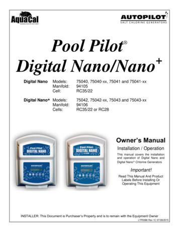
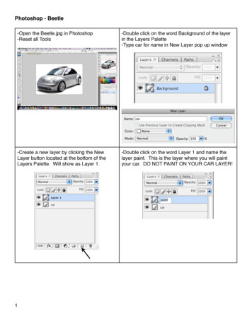
Nano-layers Create Thinner and Wider Tubular Barrier FilmsHenry G. Schirmer, BBS Corporation, Spartanburg, SCDr. Mark Pucci, Soarus LLC, Arlington Heights, IlABSTRACTRecent coextruded nano-layer blown film advances havebeen made to produce wider and thinner stalk blownbarrier film. Nylon/EVOH nano-layer clear barrier filmsas well as all polyolefin clear films were made at 4:1Blow up Ratio (BUR) using the patented (US 8,870,561)Layer Sequence Repeater (LSR). These very thin barrierfilms not only retained barrier properties but showedevidence consistent with stretch orientation in SEM30,000x microphotographs.This process worked only when the air delivered fromthe single air ring was throttled back leaving only aircooling for the bubble. Also the hot air cooled bubblehad a tendency to stick on the wooden converging plates.The thin film also produced edge wrinkles. Theseproblems were now addressed with additions to the lineand this created a new blown film process now to bedescribed.Equipment for Ultra-thin FilmINTRODUCTIONExtruder dWhile micro-layer Nylon/EVOH coextruded melts tendto have normal Blow Up Ratios (BUR) of 2:1, nanolayer melts tend to permit much higher BUR and oftenpermit making very clear blown film with a stalk orconical bubble base at 4-5:1 BUR. These are observedpractical results from the annular nano-layer diedevelopment that were not anticipated.Annular Die nano-layers are made with the use of aLayer Sequence Repeater (LSR) module insertedanywhere within a modular disk die. Whereas this diemade only micro-layers before, the insertion of a LSRhas increased the number of layers within films nowbeing made. This has a “green” translation by makingmore usable film from less plastic material consumedand thereby creating less waste on disposal.The LSR is in fact a removable module and 1 or morecan be used. This makes possible the insertion of morematerials in nano-layer form within a film structure. Anall nano-layer die capable of making 77 nano-layersusing 4 different materials has been under study withinthe BBS Films Lab. However, only one 25-nano-layermodule was necessary to accomplish the reported workin this paper.29 Layer die25 nano-layersExtruders b A cAir ring5:1 BURCollapsing FrameWound filmPicture 1 Film Line for High Stalk FilmTypical Nano-layer StructureLDPE EVA micro-layersEVA / PP 25 nano-layersLDPE EVA micro-layersFILM MAKINGLDPE / EVA / { EVA /PP/.25 Nano./ PP / EVA } / EVA / LDPELong Stalk Film A long stalk bubble was created in thefollowing picture by simply inserting an LSR having 25alternating nano-layers of PP/EVA within the ModularDisk Die. At the very high BUR of 5:1, we were notsurprised that the very thin film of 0.15 mil showedshrink film properties. A paper on this film was given atPO 2012 and picture 1 shows the labeled parts of theequipment used.The LSR created nano-layers occupied about 1/3 of thefilm structure. The rest of the structure was from a totalof 4 micro-layers, 2 on each side of the nano-layerbundle as shown in picture 2.Picture 2 Microscopic cross section showing structureAdded Controls to the High Stalk Process Because thestalk was controlled by reducing the air coming from theupper air ring at the die, the need for additional coolingafter the bubble was blown became apparent as the ratewas increased. So an additional larger air ring was madeand installed after the bubble was blown. Picture 3 showsthe lower air ring that set the blown bubble and permittedhigher rates and even thicker film to be made.1
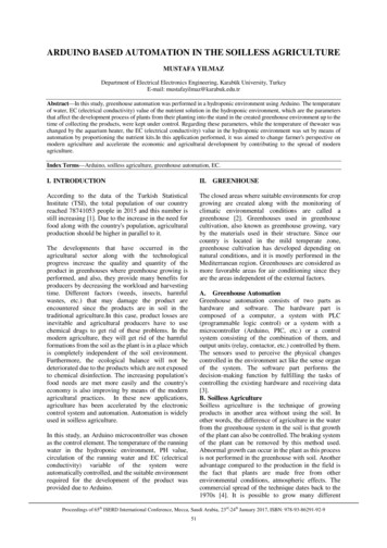
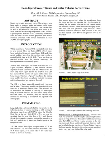
Controlled Stalk for Nano - N6/EVOHAir Converging Plates Replace SlatsUpper Air Ring setsStalkAir Converging PlatesLower Air Ring sets BubbleFinished RollAir PlatesWound RollPicture 3Control forUpperAir RingImproved Stalk Blown Film LineWith the added controls, we found that nano-layerN6/EVOH could also be blown into clear film at 4:1BUR with a more controlled shorter stalk. This is shownin Picture 4.Picture 5 Air Converging PlatesHydrostatic Bubble PressureShort Stalk for N6/EVOH Nano-FilmWater at Nip Rolls Eliminates Edge WrinklesPicture 6Water Prevents Edge WrinklesPicture 4 Precisely Controlled Short StalkWith the blown bubble set by the cooling air from thelower air ring, continuing the use of cooling air to theconverging plates where the converging film wouldliterally float on it was believed might help reducedefects such as wrinkles. When tried, this idea workedvery well using squirrel cage fans to blow air into awooden plenum with a few exit holes to supply the aircushion to the converging film. Picture 5 shows one sideof an air converging plate.In making most thin films especially when using stiffernylon/EVOH barrier materials, edge wrinkles was still aproblem. However, the use of hydrostatic pressure froma water puddle created enough outward force to stopedge wrinkles from forming. Picture 6 shows this at theconverging nip.Drawing 1 – Die with 3 Modules including LSR2
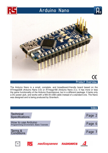
Drawing 1 shows the cells fed by each extruder. ExtruderA and d feed cells in module 1. Extruders b and e feedthe LSR, module 2. Extruders c and F feed cells inmodule 3. Capital letters designate 1.25 “ extruders andlower case letters designate 0.75” extruders. Sub t aftereach extruder designates a terminal cell. The celldiagram in Drawing 2 shows how each cell is positioned.Drawing 2 – Cell positions relative to melt inputs22/17PE/tie/{25 nano-layers EVOH/ a-N}/tie/PEThe PE was Dow 1881; tie was PX3747; EVOH was ET3803; N6 was DSM F136 and a-N was EMS G21.Each of the barrier film structures were made with a high3-4 BUR at roll speed settings of 60, 70, 100 respectivelywith the increasing sample numbers. This produced filmsranging in thickness from 40.5 micron (1.6mil) to 13.6micron (.5mil). The objective for making these very thinbarrier films was to obtain films with only moderatebarrier properties for such applications as cheesepackaging.All of the high BUR films were very clear even with themore crystalline nylon 6. The bubble pressure wasgenerally high indicating that the barrier materials mayhave developed a degree of orientation consistent withthe clarity of the film from this new double air ringblown film process.While we shall only concentrate on the three filmsdescribed here there were others that were made at BBSand tested at Soarus. Reference is made to the followingcollaborative reports.201312 O2 report for Soarnol DT 290420130805 report AT 4403 vs DT 290420131011 report for DT 290420131205 report for DT 2904As you can see from Drawing 2, the general structureof each film made from this arrangement was as followsfrom inside if the bubble to the outside using extruderletter designations as the plastic used:A/d/{b/e/ 25 nano /e/b}/c/FBARRIER BLOWN FILMThree test films were chosen from a wider array that wasmade. These represent the similarities and differencesbetween N6 and amorphous nylon. While only 38 mol %ethylene EVOH is represented here, both 29 and 44 mol% ethylene EVOH containing films were also includedto give a broader perspective of the barrier effects.The following test films were examined for barrierproperties:22/3PE/tie/{25 nano-layers EVOH/ N6}/tie/PE22/16PE/tie/{25 nano-layers EVOH/ a-N}/tie/PE08/28/14 O2 Report for BBSBARRIER FILM PROPERTIESIn order to characterize the films made for barrierperformance, the following measurements were made:Microscopic layer thickness – As the films becamethinner, the power of magnification had to be increasedfrom 2,000x to 30,000x and the Scanning ElectronMicroscope (SEM) was the best tool for highmagnification.Tabulation of layer thickness – Barrier materials innano-layer form could only be measured as a totalbecause the 25 alternating layers were generally too thinand dependent on the cross-section being made to bereliable. Generally half the total nano-layer thicknesswas assumed for each barrier material but as the picturesshow this doesn’t seem to be true either.Tabulation of O2 Barrier Results – Barrier Oxtranresults are a generally accepted as an indication of the3
barrier performance of the film in total. Caution shouldbe taken in extrapolating these results.nano-layers so thin that higher magnification was doneusing a Scanning Electron Microscope (SEM).Cross Section, Sample 22/3BARRIER FILM STRUCTURESThe three film structures below were examined photographs determined the thickness distributionof the layers.Nano-layerthickness 10 micronLayer Thickness of Sample 22/322/3 PE Tie25 nano-layersTie PE TotalET/N6µm 10.6 1.3 10.0 (.4mil)%26.2 3.2 24.71.7 16.9 40.5 (1.6mil)Total thickness(40.5 micron)4.2 41.7 100by Laser Digital Microscope(x2,000)Shown on the right is a 2000x microphoto of sample22/3 containing clear nano-layers of EVOH/ N6 whichare difficult to resolve but are about 25% of the total filmthickness of 40.5 micron. High film clarity may becontributing to the difficulty in seeing the nano-layers.Cross Section, Sample 22/16Nano-layerthickness 6 micronLayer Thickness of Sample 22/1625nano22/16 PE Tie layersTie PE TotalET/a-Nµm 8.2 1.5 6.3 (.25mil)5.5 15.0 32.8(1.3mil)% 32.6 3.9 22.25.8 35.5 100µm 8.0 1.6 5.9 (.23mil)1.6 13.9 31.1(1.2mil)% 25.8 5.2 19.05.2 44.8 100N 1Totalthickness(32 micron)N 2by Laser Digital Microscope(x2,000)Shown on the right is a similar microphoto of sample22/16 containing clear nano-layers of EVOH/amorphousnylon which again are difficult to resolve.Cross Section, Sample 22/17Layer Thickness of Sample 22/17Nano-layerthickness(2.1 micron)25 nano-layers22/17 PE TieTie PE TotalET/a-Nµm 5.4 1.2 2.1(.08mil)1.1 3.9 13.6(.5mil)% 39.6 8.5 15.57.9 28.4 100µm 4.9 1.1 2.1(.08mil)1.2 5.5 14.8(.6mil)% 33.1 7.4 14.28.1 37.2 100N 1N 2The thinnest clear film also contained the same 38 mol %EVOH/amorphous nylon as above. Sample 22/17 hadTotalthickness(14 µm)by Laser Digital Microscope(x2,000)4
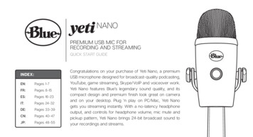
BARRIER FILM STRUCTURESUSING SEMThe SEM produced some extraordinary insights to thecondition that may be existing within each of the nanolayers. Each of the samples below showed some unusualtraits.Cross Section, Sample 22/3 (15,000x)Sample 22/3 still drew a blank on resolving the nanolayers. This was very unusual behavior becauseEVOH/N6 nano-layers had always been seen clearly inthe past. There is no immediate explanation for this butthe process conditions leading to a high BUR may havealtered the refractive index of the 2 polymers.Cross Section, Sample 22/16 (30,000x)generally clearer film while retaining high or goodbarrier performance.Cross Section, Sample 22/17 (30,000x)Sample 22/17 is stretched further to make the thinnestfilm of this series. While the BUR generally remains thesame as in sample 22/16 the stretch in the machinedirection was increased giving the nano-layers whatappears to be a lesser node to thinner area contrast.BARRIER MEASUREMENTS90%RH OTR Measurement ResultsThe Gray color area are the OTR results of ET/Ny nanolayers films.-To take into account the effect of amorphous Ny andNy6, we compared the OTR results with OTR of 25nano-layers of DT/DT (18I) and 25 nano-layers ofAT/AT (18M)NanoNormalizedEVOH EVOHlayersEthylOTRSample TotalThickne OTRene[cc/m2.dssIDThickne[cc 4um/contentay.atm][um]ssm2 day a[um]tm]2938Sample 22/16 on the other hand clearly shows both theamorphous nylon and EVOH in a very unusual node likelayer appearance. Each nano-layer appears to show traitsconsistent with cold stretched film especially in thetransverse direction as shown here where thinner areaswould generally stretch first creating thinner stretchedareas and thicker less-stretched areas. If these layerswere truly stretched, this would be consistent with aRef. 18I aN2.1961.05252.1861.052322/310.0315.039ET/N6Ref.44 18M4.4294.432(AT/T)Equipment; Ox-Tran 2/21Conditions; 20 degree C,90%RH (Outermost/innermost)5
Please note that an average of 5 points were measured todetermine the Oxygen Transmission Rate. OTR wasmeasured twice at different parts of the sample.9.10.The EVOH thickness of all films is taken as a half oftotal nano-layers thickness.Interestingly, all the thin high BUR barrier films hadsignificant barrier properties. Coupled with this is anindication that the amorphous nylon in combination withEVOH may enhance the overall barrier especially underwet conditions.RESULTS AND CONCLUSIONS11.12.13.14.1.2.3.4.A new blown film process was createdusing a dual air ring control system incombination with nano-layer coextrusion tocreate controlled stalk blown films of veryhigh BUR.The effects of very high BUR were seen inthe microphotographs of the films that wereconsistent with orientation effects in thetransverse direction often seen during coldstretching.All of the films made did not loose oxygenbarrier properties because of the high BUR.Amorphous nylon used with EVOH innano-layer form may actually haveincreased the barrier performance of thefilms.REFERENCES1.2.3.4.5.6.7.8.The Modular Disk Coextrusion Die –Schirmer Polyolefins 2000New Compositions of Matter from TheModular Disk Coextrusion Die - Schirmer,Love, Schelling, Loschialpo - ANTEC2000Micro-layer Coextrusion Technology Baer,Jarus, Hiltner - ANTEC 1999Modular Disk Coextrusion: ProductionRate Tests with the 9” flex-Lip DieSchirmer - Future-Pak 199925 Micro-layer Blown Film CoextrusionDie – Schirmer – Polyolefin s 2008Exploratory Experiments on Solid-StateFoaming of PLA films and COC/LDPEMulti-layered Films - Lu, Kumar, Schirmer- ANTEC 2009Improved Flexible Packaging FilmPerformance via Layer Multiplication- SamIuliano – Polyolefins 2009Nano-layers in Blown film – Schirmer,Jester, Medlock – Polyolefins 200915.16.17.Nano-layers in Blown Barrier Films –Schirmer, Jester, Medlock, Schell – PO2010Oriented Blends of Polybutene –1 andPolypropylene–Schirmer–USPat.3,808,304A.M. Chatterjee, “Butene Polymers”,Encyclopedia of Polymer Science andEngineering, Vol 2, 2nd. Ed, 590 (1985)Nano-layers in Blown Barrier Films (part2) PO 2011– Schirmer, Schell, Pucci &ChatterjeeUltra-Thin Nano-layer Stretch Shrink FilmPO 2012 – Schirmer, SchellNano-layer Micro-layer Advances inShrink Film – PO 2013 Schirmer, Pucci,GlezNano-layer Structural Advances CreateThinner and Wider Tubular Films – TAPPI2014, SchirmerNano-layer Structural Advances CreateThinner and Wider Tubular Films (2) –FlexPack 2014, SchirmerNano-layer Structural Advances CreateThinner and Wider Tubular Barrier FilmsPO 2015, Schirmer, PucciAUTHORSHenry G. SchirmerBBS Corporation2066 Pecan DriveSpartanburg, SC 29307Tel: (864) 579-3058E-Mail: hschirmer@att.netDr. Mark PucciSoarus LLC3930 Ventura Drive, Suite 355Arlington Heights, IL 60004Phone: (847) 255-1211E-Mail: mpucci@soarus.comACKNOWLEDGMENTSDSC,SEM & Barrier results from Soarus1. Noriyoshi Inoue: ninoue@soarus.com2. Kenji Ninomiya: kninomiya@soarus.com3. ShinichiHori: shori@soarus.com6
thinner, the power of magnification had to be increased from 2,000x to 30,000x and the Scanning Electron Microscope (SEM) was the best tool for high magnification. Tabulation of layer thickness - Barrier materials in nano-layer form could only be measured as a total