Transcription
(K AFWAL-TR-82-2057Volume IIIHIGH VOLTAGE TESTING:GENERATOR TEST PROCEDUREW.G. DunbarBoeing Aerospace CompanyP.O. Box 3999Seattle, Washington 98124July 1982Find Report for Period 29 September 1979 - 1 April 1982Apps ofor pulbic relew; distribution unlimitedIRV&-' DEC 1 4 1982Air FOl VMt A vo4autelW LaboratoriesAM FAFoU w,COhinw4"WWORMWAi'Pr.Ba*Ssn, Oh io 45433A
NOTICEWhen Government drawings, specificat.*ons, or other data are used for any purposeother than in connection with a definitely related Government procurement operation,the United States Government thereby incurs no responsibility nor any obligationwhatsoever; and the fact that the government may have formulated, furnished, or inany way supplied the said drawings, specifications, or other data, is not to be regarded by implication or otherwise as in any manner licensing the holder or anyother person or corporation, or conveying any rights or permission to manufactureuse, or sell any patented invention that may in any way be related thereto.This report has been reviewed by the Office of Public Affairs (ASD/PA) and isAt NTIS, it willreleasable to the National Technical Information Service (NTIS).be available to the general public, including foreign nations.This technical report has been reviewed and is approved for publication.DANIEL L. SCHWEICKARTPROJECT ENGINEERPAUL R. BERTHEAUDTechnical Area ManagerPower Systems BranchAerospace Power DivisionFOR THE COMMANDERJAMffD. REMChief, Aerospace Power DivisionAero Propulsion Laboratoryifor"If your address has changed, if you wish to be removed from our mailing list,the addressee is no longer employed by your organization please notify5NU .W-PAFB, OH45433 to help us maintain a current mailing list".Copies of this report should not be returned unless return--is required by securityconsiderations, contractual obligations, or notice on a specific document.
r.SECURI'Y CLASS;FICATION OF THIS PAGE (When VatEntered)REPORT DOCUENTATION PAGEI.2. GOVT ACCESSION NO.REPCORT NUMBERAFWAL-TR-82-2057 VOL4.REAL iNSTRUCTIONSBEFORE COMPLETING FORMIllt/TYPE OF REPORT & PERIOD COVERED3.TA CLE (and Subtitle)FINAL REPORT29 SEP 79 - 1 APR 82HIGH VOLTAGE TESTING.GENERATOR TEST PROCEDURE7.RECIPIENT'S CATALOG NUMBER3.6PERFORMINGW. G. Dunbar9.NUMBERCONTRACT OR GRANT NUMBER(&)S.AUTHOR(s)ORG. REPORTF33615-79-C-2067PERFORMING ORGANIZATIONPROGRAM ELEMENT. PROJECT, TASKAREA & WORK UNIT NUMBERS10.NAME AND ADDRESSBoeing Aerospace Co.P. 0. Box 3999Seattle WA981243145-32-50CONTROLLING OFFICE NAME AND ADDRESS12.REPORT DATEAero Propulsion LaboratoryAFWAL/POOS-2Wright-Patterson AFB OH 4543313.NU1BER OF PAGESIt.14.MONITORING AGENCY NAME 6JUL 8226ADORESS(it different from Controlling Office)15.SECURITY CLASS. (of this report)UNCLASSIFIED15a. N STATEMENT (of this Report)Approved for Public Release:Distribution Unlimited.17.DISTRIBUTION STATEMENT (of the abstract entered In Block 20, If different from Report),SUPPLEMENTARY NOTES19. KEY WORDS (Continu* on reverse side if necessearand identify by block number)Airborne EquipmentPulse TestsHigh Power SourcesDielectric WithstandInsulation ResistancePartial Discharge TestsVoltageGenerator CoilsTestsHigh Voltage20. ABSTS? kCT (Continue on ruvera* aide If necessary and identily by block number)-- The/ )Iigh Voltage Testing: Specifications and Test Procedures" documentrefer,-ed to in this report pertains to high voltage/high power airborneequipm ent. A test plan was developed to apply the test parameters uf saiddocument to a specific high power generator prototype design. This testprocedure covers the general high voltage tests required for the highvoltage stator coils and assembly in this high power alternating current,three phase generator. -- DSU1A.FORMA RIT,EDITION OO6S IS OBSOLETEAF(tOVSECURITY CLASSIFIZ:,%TION OF THIS PAGE ("oen Dots Entered)
FOREWORDPresented herein is the Boeing Aerospace Company's Final Report covering workaccomplished on Contract F33615-79-C-2067 for the period of September -. 1979through May 1, 1982. This contract is being performed for the Aero PropulsionLaboratory, Air Force Wright Aeronautical Laboratories, Air Force SystemsCommand, Wright-Patterson AFB, Ohio. The program is under the technical directionof Daniel Schweickart, AFWAL/POOS-2.Personnel participating in this work for the Boeing Aerospace Company were W. G.Dunbar, the technical leader, and S. W. Silverman, the program manager.*1Fl-4)o-owJ l . ;-,. -L Li iii!- .
TABLE OF CONTENTSPAGESECTION1.0IPROGRAM OBJECTIVES3"2.0 SCOPE"3.0 BACKGROUND"4.0 IREMENTS95.1Description9""5.2Tests9 ."6.0TEST PLAN5.0 *:""i6.1General116.2Ambient 213"7.0 TEST SEQUENCE7.113In-Process Tests13"7.2 Ancillary Equipment Tests88.0 7.3Generator Test137.4Dynamic Test1315TESTS8.1Insulation Resistance15Procedure158.1.1*8.2"8Dielectric Withstanding Voltage tions1617"8.3 Pulse al DischargeV
TABLE OF CONTENTS nts198.4.3Connections20Test Results2325APPENDIX Avi
LIST Or ILLUSTRATIONSFigure3-1Hicogh Voltage/High Power Airborne System"8-1i O-e Voltage Wave ShapeGc.i:'ator-Parital Discharge Test FacilityMachine Pulse Voltage Withstand Envelope88-2A-Ivii?&6172125 -
LIST OF TABLES"TABLEPAGENumber8-1Dielectric Withstanding Voltage168-2DWV Instruments168-3Pulse Voltage Magnitude188-4Pulse Test Instrumentation188-5Partial Discharge Test Voltage198-6Partial Discndrge Connections20SSIS viii, o-.*.
1.0PROGRAM OBJECTIVESThe objectives of this program are as follow-:a.Perform high voltage tests on capacitors, cable assemblies and parts, and coils.b.Dessit; . fabricate, and evaluate a high voltage standard test fixture to be usedfor measuring tIe void content in various high voltage insulation systems.Specify and procure a 150 kV, 400 Hz poxwer supply for partial dischacgemeasurements.,L.ate the Tests a-,,,t Specifications Criteria Documents completed in U.S. Air-. ,ntract F33615-77-C-2054 to include the findings from the test article-tions.e.Develop a high voltage gei erator test procedure.f.Update of the Airborne High Voltage Design Guide completed on UoS. Air Ferce. contract F33615-76-C-2008,g.Devlop a Spacecraft High Voltage Design Guide.Ue;U.1!
2.0 SCOPEThe major task reported in this volume is to:oDevelop the genteral high voltage test requirements for a h gh voitage, highpower, alternat'ng current generator.q3
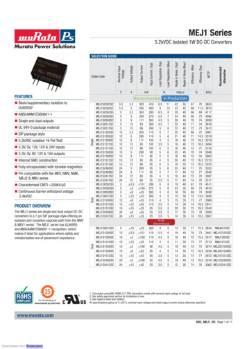
K3.0BACKGROUNDrwasIn contract F33615-77-C-2054, a High Voltage Specifications and Tests criteria dJcumentwritten for U.S. Air Force .airborne power supplies and components which supplymegawatts of power at tens of kilovolts to high power/high voltage systems. Ageneralized power s ,urce and power conditioring system is shown in Figure. 3.-I for aturboalter lator dri.ven system. However, the turboalternator care be replaced with a M: IDrequipment, which imply compact systems with high density packaging.power supply. Emphasis has been olaced on minimum weight and volume airborneThe eight criteria documents were written .in accordance with military specifica tions for:cables, cable assemblies, capacitors, connectors, converters, power characteristics, powersources, and transformers and inductors.Included in each criteria document were high voltage t.ests and test pa -ameters based oninsulation design parameters and engineering judgment. in this program test articles were*selected which represented components or component parts for the components discusssed*in the criteria documents.The selected test ar ticles were:Cables-'Cable AssembliesConnectorsAlternator Coil (Sections)Alternator CoilsTransformer CoilsPower Th-anslormer1Pulse T.-arsformers a.epacit.orsEach te t artic le was tested for:Insulation ResistanceOielectric. Withstanding VoltagePulse VoltageParti.al Discharge (Corona)
. I" . -.-----.- ,-.--- -------F oilowing completion of the test program, the Test and Specification Criteriadocuments were updated xo reflect the findings of this test program.A generator test procedure %as developed using the data from the generator coil tests inVolume I, "Test Program Report", and the generator high voltage test procedure fromVolume 2, "Specifications and Procedures", Appendix G, Power Sources. This testprocedure c.overs the general high,-voltage tests required for a high-voltagehigh-poweralternating current generator; one of the selected power sources for the high powersystem shown in Figure 3.1.TURBINEFUELSUPPLYGAS GENERATOR00 RECTIFIER/FILTERIINVERTERELECTRICALGENERATOR* CHARGING NETWORKRULSEFORMING NETWORKS PROTECTION NETWORKSXFMRCABLEHIGHPOWERLOADASSYSWITCH, AS REQUIREO DY THELOAD(IF REQ'D)GAS TURBINE(NON AIR-BREATHING)POWER CONDITIONING SUBSYSTEMFigure 3-1: High Volbge/Hikh, Power Airborne System6. ."-'' . ,'. .,",."' :i -" ". .a
4.0INTRODUCTION4A1Scope. This test procedure covers the general high voltage tests required for thehigh voltage, high power alternating current generator described as one of theselected power sources in U.S. Air Force technical document AFAPL-TR-82-2057,Volume 2, High Voltage Testing: Specifications and Test Procedures.4.2Tests. The generator test procedure is new. This rep3rt contains the high-voltagetests and test procedures required to evaluate the generator insulation integrity."Generator coils and coil segments were tested as part of the test evaluation reportedin Volume I of this report. These data were used to determine the tests and testparameter limits to avoid damage to the insulation system, yet give insulationintegrity assurance.-,'4.3Procedure. This test procedure will cover the generator armature coils in thegenerator assembly. The armature coils will include, but not be limited to, phaseto-phase tests and coin-to-coil tests. The generator assembly will be for either aprototype, developmental, or production generator.7
5.0REQUIREMENTS5.1Description. This test procedure covers the tests required for the insu'ationintegrity of a high power, high voltage, short liletime alternating, current generatorfor use in or in conjuction with airborne equipment. The pertinevt electr-calparameters of the generator armature are:Output Power20.9 MWVoltage, L-L29.6 kVVoltage, L-N17.1 kVVoltage, Coil-to-Coil2.8 kVPhase Current408 amperesNumber of Phases3Output Frequency200 HzUseful Life100 hoursDuty Cycle5 minutes ON10 minutes OFF5.2Tests. The following tests shall be performed using production or developmentgenerator armature coils:insulation resistancePartial dischargeDielectric withstanding voltagePulse9.
. . . .-,. -. .-6.0TEST PLAN6.1General. The generator assembly will be tested according to the acceptance test-oprocedure outlined in document AFAPL-TR-82-2057, Volume 2, High VoltageTesting: Specifications and Test Procedures , and the manufacturer's approved testprocedure for the generator.6.2Ambient Conditions. Ali tests shall be performed at 25 50C, atmospheric pressureof 100 20 kilopascals, and relative humidity of 90 percent, maximum. The testarticles shall be conditioned by remaining at ambient temperature, pressure, andhumidity for 4 hours prior to testing.6.3Preparation, The test article and high voltage test equipment, high voltageterminations, connections, and exposed surfaces shall be grounded at all timesexcept when under test. High voltage insulators shall be cleaned with alcohol orfreon 'o remove dirt and grease which may cause surface discharges on theinsulators, terminations, and interconnects. The test article shall be grounded tothe same common ground as the high voltage test equipment. Ground leads shall benext to the floor and made of a braid or wire equivalent to an AWG #6 or larger.6.4Safety. The following safety procedures shall be in force during high voltagetesting.6.4.1Equipment. Test equipment and the test area shall be protected withpersonnel exclusion barriers and warning lights and/or an interlocksystem to prevent unauthorized personnel from entering the test area.Warning signs shall be conspicuously posted.6.4.2Handling. Because of the high voltage, caution must be exercised inusing the HV test equipment and in handling the interconnecting leads tothe test article. When connecting or disconnecting the cables, powermust be removed from the circuits. Reduce the test voltage to zerovolts and turn off the test equipment.6.4.3Grounding. Time must be allowed for the high voltages to bleed offbefore attempting to ground the test equipment and test article. Fifteen(15) seconds is sufficient.11, ,. ''
6.4.4Caution. Before applying power to the test article, all personnel shall beat least six (6) feet away from the high voltage test article andinterconnections. The grounding straps shall be removed from the testarticle after the test director is assured that all safety precautions aremet.12,. , -, ,.,. .
7.0TEST SEQUENCEThe following test sequence shall be followed to gain sufficient information so as toprevent damage to the test article;7.1A.In-process testsB.Ancillary equipment testsC.D.Generator assembly testsDynamic testIn-process Tests. In-process tests arc recommended, but not mandatory, to assureinsuiation integrity of all armature coils prior to interconnection of the coils toform the three phases and the neutral connection. These tests are coil-to-coil andare limited to insulation resistance and dielectric withstanding voltage.7.2Ancillary Equipment Tests. High voltage bushings, terminations, andinterconnecting cabling should be tested for dielectric withstanding voltage andinsulation resistance. These tests are cecommended but not mandatory tests. Thesecomponents may be tested individually or interconnected.7.3Generator Test. The generator shall be visually inspected and subjected to thefollowing tests in the following sequence:7.4A.Insulation resistancerB.Partial dischargesC.Dielectric withstanding voltageD.E.PulsePartial dischargesF.Visual inspectionDynamic Test. Six high voltage partial discharge tests are requi.-ed with thegenerator operating at full voltage and no load; the partial discharge tests may beconducted before or after the other electrical/mechanical/environmental tests. Thepartial discharges per phase shall not exceed:10 per minute over 1,000 pcNone to exceed 10,000 pc13
. .8.0.-. .TESTSHigh voltage verification and acceptance tests shall include, but not be limited to-the following: insulation resistance, dielectric withstanding voltage, pulse andpartial discharges.8.1Insulation Resistance. When tested for insulating resistance at a potential of 500 50 Vdc, the minimum insulation resistance shall be greater than 1000 megohms.8.1.1Procedure. Insulation resistance shall be measured between thegenerator phases and the generator frame. The three phase leads shallbe connected together. A potential of 500 50 Vdc shall be appliedbetween adjacent phases and frame. The potential shall be applied for aperiod of one minute, minimum. However, if a stable reading is obtainedin less than one minute, and the results are in excess of 1000 mehogms,the minimum allowable, the test may be terminated.In a similar manner, a coil-to-coil insulation resistance test may be madein process with the same potential applied between adjacent coils. Areading greater than 1000 mehogms again indicates a "pass" condition.During the energization period, the insulation resistance shall bemeasured with a calibrated General Radio, GR-1862C, InsulationResistance Bridge, or equivalent. The insulation resistance shall be 1000megohms, minimum.8.20hi-,lectric Withstanding Voltage (DWV). The test articles shall be tested for DWV.When tested to the specified test parameter listed in Table 8-1, for one minute,there shall be no evidence of breakdown, arcing, or other visible damage to the testarticle. The applied voltage frequency shall be 400 Hz.8.2.1Procedure. The three phase leads shall be connected to a high voltageelectrical test circuit. The ground lead for the high voltage electricaltest circuit shall be connected to the generator frame cind ground. Thecomponent shall be tested in accordance with MIL-STD-202, Method 301,with the test parameters listed in Table 8-1. The duration of the test15
shall be one minute 5 seconds. Leakage current shall be measured andplotted for each insulation configuration.Table 8-1Dielectric Withstanding VoltagesConfigurationRated Voltage,kV acoCoil-to-CoilDWV,kV ac2.84.5 0.217.127 1(in process)oGeneratorPhases-to-Frame8.2.2Instruments. DWV measurements shall be made using certifiedcalibrated instruments. Equipment and instruments, or equivalent, areshown in Table 8-2.Table 8-2DWV InstrumentsTestEquipmentManufacturerModeloAC Power SupplyTBDTBDoElectrostatic VoltmeterG.E.TBD8.2.3Connections. The assembled generator shall be tested with the threephases (A, B, and C) connected together and to the high potentialterminal of the high voltage source. The return line of the high voltagesource shall be connected to the generator frame.The in process coil-to-.5 ' test shall be made by applying high voltage betweenadjacent coils.16
8.3Pulse Test. The test articles shall be subjected to 3 to 5 pulses separated aminimum of one minute. Testing shall be discontinued of there is evidence ofbreakdown, arcing, or other physical damage to the test articles.Procedure. Each test article shall be connected to an electrical r-ircuitas specified in IEEE Publication, Number 4, 1978, ANSI C-57, or ANSI C-8.3.193. The pulse voltage levels shall be as shown in Table 8-3. The pulsevoltage profile shall be similar to that shown in Figure 8-1 or equivalent,using the instrumentation shown in l able 8-4.1.0 -------0.9 'kVPER UNIT0.5"-I"01.250TIME - MICROSECONDSFigure81: Pjte Volt p Wave ShpeTest voltage magnitudes shall be determined from the voltagescalculated using the graph from Reference 1, to the values shown inTable 8-3. A calculation of the pulse test voltage is shown in theAppendix. These values were verified by evaluation testing of thegenerator coils.Reference 1. R. G. Rhudy, "Impulse Voltage Strength of AC Rotatiai Machinery", IEEEPES Winter meeting, Atlanta, GA, February, 1981, Paper 81WM 182-5.17".".
Table 8-3 Pulse Voltage MagnitudePu'seRatedTestVoltage s-to-framekVkV2.81017.160Table 8-4 Pulse Test InstrumentationInstrumentManufacturero100 kV Marx Connections. The assembled generator shall be tested with the threephases (A, B, and C) connected together and to the high potentialterminal of the high voltage source. The return line of the high voltagesource shall be connected to the generator frame.3.4Partial Discharges. The test articles shall be tested for partial discharges. Whentested for partial discharges to the specified test parameters, there shall be noevidence of breakdown, arcing, or other visible damage to the test article.8.4.1Procedure. Each test article shall he connected to the high voltagecircuit of a partial discharge test facility and tested for partialdischarges and/or corona. Generator coils shall be tested with acvoltages only. The following details shall apply:(a)Magnitude of test voltage - 100% rated voltage; as specified inTable 8-5;18": " :" .".' " ".- ".'.' - '--' -"" -"". "-."-"""-""" "I
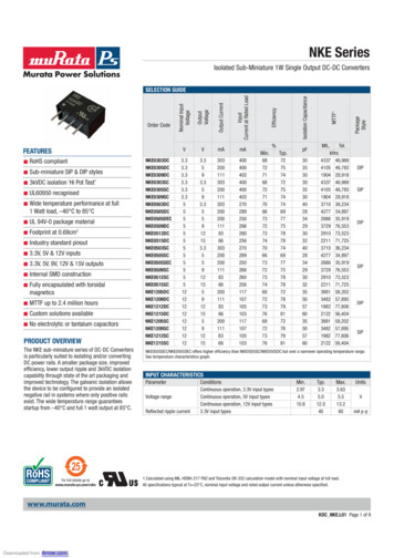
(b)Nature of potential - ac;(c)Points of application of test voltage; as specified in Table 8-6;(d)Examination after testthe test article shall show no visibledamage;(e)Partial discharges shall not exceed more than 10 discharges perminute above 1,000 pc. Partial discharges greater than 10,000 pcare unacceptable;"(f)Duration of application of test voltage:(1)Applied Voltage Test - Voltage shall be increased from 0.0volts to operating test voltage at a rate of 500 volts persecond. Partial discharges shall be measured for 3 minutesafter operating voltage is obtained. Voltage shall be rampeddown at the same rate as it was ipplitd.(2)Dynamic Test - Partial discharges shali be measured for 3minutes after operating at full voltage for one minute.Partial discharges within the test article shall be calculated per ASTM D1868 orASTM D3382-75.Table 8-5 Partial Discharge Test VoltageTestRatedTestAr.tideVoltage,Voltage,kV ackV .1oCoil-to-CoiloGeneratorInstruments. Partial dicharges shall be measured using either the8.4.2corona test facility located at the U.3. Air Force Aero PropulsionLaboratory AFWAL/POOS-2, which includes a 17000-3 Fartial DischargeDetector, a 150 kV (17187-2) Power Separation Filter, 400 Hz (17189-9)Power Separation Filter manufactured by 3. G. Biddle Co.; an ND6019- .*. . .*-." .;
Nuclear Data, inc., Multichannel Analyzer; and a 150 kV: 4!00 Hz PowerSupply manufactured by Hipotronics, or an equivalent ttst facility.Connections. Test article connections shall be as shown irn Table 8-6 and8.4.3Figure 8-2.Table 8-6 Partial Discharge Connections"ConnectionTest00-IVDynamic TestsNegativeOpenPhase APhase BPhase C, FramePhase BPhase CPhase A, FramePhase CPhase APhase AFramePhase B, FramePhase B and CPhase BFramePhase C and APhase CFramePhase A and BFrameNoneApplied Voltage Tests Phase A,B,C.5 ,' -',, ' "",iL:Y"" " " "".r''' ,".''""',"," " --":'*' - """/ """'"'20" ' ,:-' " . . " ".,T .' J -, ' * . . . . .p,."*" -' . -
7-7wI"zcc211ii211
9,0TES'I RESULTSAll test data shall be recorded on Approved Engineering Test Laboratories (AETL)data sheets. Copies of the data sheets are attached. In the event of any faiiure ordeterioration of the article, all pertinent data shall be recorded, such as time, typeof failure, test parameter, a.nd environmental conditions. Before testing resumes,engineering approval is required.w23-.: .::. :. : .-. .
APPROVED ENOIUNEERItC TEST LABORATORIESDateLaboratoryTest DirectorTert CornductorTest ArticleModel NumberSerial e NegativeVoltageAppliedkVacLUakage TimeCurrent e?artialDischarges.Partial DischargesSurgePartiai Discharges24Pass/Fail
APPENDIX A"GENERATOR TEST VOLTAGE CALCUALTIONThe generator pulse voltage calculations were based upon the findings of the RotatingM.Achirnery Committee of the IEEE Power Engineering Society (PES) presented at the IEEEPES Winter Meeting in Atlanta, Georgia, February, 1981. The findings of the committeewere that the original ASA pulse voltage insulation strength for Vac rotating machinerywas at least the commercial value, i.e., 1.25 times the crest of the dielectric withstandingvoltage (DWV) acceptance test, regardless of pulse waveshape. The DWV of the majorinsulation to ground is:DWV V2?1 2 V) kVV generator line-to-neutral (ground) voltage.Then the pulse voltage is at least:V pulse 1.25 \V/2i 2V) kV.Recent study by the working group found that the pulse voltage crest (line-to-ground) perunit voltage varies with the wave front of the applied pulse as si.own in Figure A-I.Although the insulation system of some rotating machines are designed to have greatertolerance to pulse voltages than others, the data in Figure A-I is consideredrepresentative of the pulse capability of machines developed to withstand pulse voltages.The data from Figure A-I were used to calculate the impulse voltage used in this testprocedure.S-V3.V2 ,2V-V--v.V00.2Figure A-1MACHINE VOLTAG1, KV0 .212I PER U N IT2V1l R1 SFV1 .PIW345FRONT, MSithsLolV6ng78Machine Pulse Voltage Withstand Voltage
*,f: , r '- - '-'': --; '- -'' , - .o*. . .-oo. o.-,The pulse voltage front has a nominal 1.2 microsecond rise to crest voltage, thatis, t 1.2.s. From Figure A-I the slope of the curve for pulses with wave fronts lessthan 0.02 'Ps isVI 5t I per unit volts, VI pulse voltage line-to-ground. For wave fronts with risetime between 0.02 and 5.0Ijs,,*VI 0.5t 1.9 per unit volts. Using a value of 1.2 )is; V1 05(1.2) M.9 25 per unit voltsline-to-ground.For these tests the test voltage can be calculated to be:VI V2 -V(2.5)where V is the nominal rated voltage, rms.thenVi-cc V22.8 x 2.5) 9.92 kV peak, coil-to-coil.For the generator phases to frame voltage the value is:Vl.pf V 2-(17.1 x 2.5)L.Sev.,-CfMtVA PRiIspnTOf4O isa-660.3 kV peak, phase-to-frame.59-06ZI6452626 -r .
8.2 Dielectric Withstanding Voltage (DWV) 15 "8 8.2.1 Procedure 15 8.2.2 Instruments 16 . A-I Machine Pulse Voltage Withstand Envelope 25 - vii. LIST OF TABLES "TABLE PAGE Number . "Test Program Report", and the generator high voltage test procedure from Volume 2, "Specifications and Procedures", Appendix G, Power Sources. .