Transcription
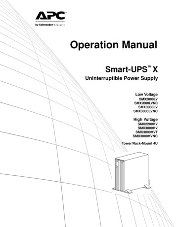
Operation ManualSmart-UPS XUninterruptible Power SupplyLow h 87aTower/Rack-Mount 4U
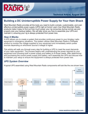
OverviewProduct DescriptionThe APC by Schneider Electric Smart-UPS is a high performance uninterruptible power supply (UPS). TheUPS provides protection for electronic equipment from utility power blackouts, brownouts, sags, and surges, smallutility power fluctuations and large disturbances. The UPS also provides battery backup power for connectedequipment until utility power returns to safe levels or the batteries are fully discharged.This user manual is available on the enclosed CD and on the APC by Schneider Electric web site, www.apc.com.Important Safety MessagesRead the instructions carefully to become familiar with the equipment before trying to install, operate, service ormaintain it. The following special messages may appear throughout this manual or on the equipment to warn ofpotential hazards or to call attention to information that clarifies or simplifies a procedure.The addition of this symbol to a Caution product safety label indicates that a hazard exists that canresult in injury and product damage if the instructions are not followed.The following safety messages may appear throughout this manual to warn of potential hazards.CAUTIONCAUTION indicates a potentially hazardous situation which, if not avoided, can result in equipment damage and minor ormoderate injury.CAUTIONCAUTION indicates a potentially hazardous situation which, if not avoided, can result in equipment damage.Safety and General InformationInspect the package contents upon receipt. Notify the carrier and dealer if there is anydamage.Read the Safety Guide supplied with this unit before installing the UPS. Adhere to all local and national electrical codes. This UPS is intended for indoor use only. Do not operate this UPS in direct sunlight, in contact with fluids, or where there is excessive dust orhumidity. Be sure the air vents on the UPS are not blocked. Allow adequate space for proper ventilation. The battery typically lasts for three to five years. Environmental factors impact battery life. Elevatedambient temperatures, poor quality utility power, and frequent short duration discharges will shorten batterylife. Connect the UPS power cable directly to a wall outlet. Do not use surge protectors or extension cords. The batteries are heavy. Remove the batteries prior to installing the UPS in a rack. Always install external battery packs (XLBPs) at the bottom of the rack. The UPS must be installed abovethe XLBPs. The UPS display interface will recognize as many as 10 external battery packs connected to the UPS.However there is no limit to the number of XLBPs that can be used with the UPS. Refer to “Specifications” on page 2 for UPS and battery weight.Smart-UPS X 2000/2200/3000 Vac XL 120/208/230/240 VA Tower/Rack-Mount 4U1
SpecificationsFor additional specifications, refer to the APC by Schneider Electric web site at www.apc.com.Operating0 to 40 C (32 to 104 F)TemperatureStorage-15 to 45 C (5 to 113 F)charge UPS battery every six monthsMaximumElevationOperating3,000 m (10,000 ft)Storage15,000 m (50,000 ft)0% to 95% relativehumidity,non-condensing0 to 40 C (32 to 104 F)Maintenance free,sealed lead acidBattery cartridge weight: 23.8 kg (52.4 lb)UPS weight: 17.2 kg (38 lb)UPS battery cartridge weight: 41 kg (90.4 lb)SMX120BP chassis weight: 13.24 kg (29.2 lb)SMX120BP chassis battery cartridge weight: 47.54 kg (104.8 lb)HumidityBattery2Smart-UPS X 2000/2200/3000 Vac XL 120/208/230/240 VA Tower/Rack-Mount 4U
Product OverviewFront panel featuresDisplay interface panelUPS battery cable and connectorBattery compartmentBezelssu0783a Rear panel featuresSMX2000, 120 VacSMX3000, 120 VacGROUP 2GROUP 1GROUP 3su0756asu0757aSMX2200/SMX3000, 230 VacSMX3000, 208 VacGROUP 1GROUP 1GROUP 2GROUP 3GROUP 2GROUP 3su0755asu0754aSmart-UPS X 2000/2200/3000 Vac XL 120/208/230/240 VA Tower/Rack-Mount 4U3
Rear panel features continued SmartSlotUse the SmartSlot to install an optional Network Management Card (NMC). Chassis ground screwThe UPS has a ground screw for connecting the ground leads on transient voltagedevices. Prior to connecting a ground lead, disconnect the UPS from AC power. Utility power cableUse the power cable (supplied), to connect the UPS to utility power. UPS circuit breakerreset buttonPress this button to reset the UPS circuit breaker after an overload condition hasoccurred. Controllable OutletGroup 1Connect critical electronic devices such as a computer, monitor, modem or other datasensitive devices to these outlets. Controllable OutletGroup 2Connect peripheral electronic devices to these outlets. Controllable OutletGroup 3Connect peripheral electronic devices to these outlets External battery connectorUse the external battery cable to connect the UPS to an XLBP.XLBPs provide extended runtime during power outages. The UPS can support up to10 external battery packs. EPO terminalThe Emergency Power Off (EPO) terminal allows the user to connect the UPS to acentral EPO system. Serial portTo use PowerChute software, connect the serial cable (supplied), to the Serial port.Use only interface kits supplied or approved by APC by Schneider Electric. Anyother serial interface cable will be incompatible with the UPS connector. USB portConnect a USB cable from a computer to use power management software.Note: Serial and USB communication can only be used individually, theycannot be used at the same time.InstallationUPSFor UPS installation instructions, refer to the Smart-UPS X 2000-3000 VA Installation Guide that issupplied with the UPS. The guide is also available on the enclosed User Manual CD and the APC bySchneider Electric web, site at www.apc.com.PowerChute network management softwareFor installation instructions, refer to the PowerChute software CD supplied with the UPS. Installationinstructions are also available on the APC by Schneider Electric web site, www.apc.com.External battery pack (optional)For installation instructions, refer to the Smart-UPS X 2000-3000 VA External Battery PackInstallation Guide that is supplied with the external battery pack. The guide is also available on theenclosed User Manual CD and the APC by Schneider Electric web, site at www.apc.com.4Smart-UPS X 2000/2200/3000 Vac XL 120/208/230/240 VA Tower/Rack-Mount 4U
OperationConnect EquipmentCAUTIONRISK OF EQUIPMENT DAMAGE Adhere to all local and national electrical codes. Wiring should be performed by qualified electrician. Always connect the UPS to a grounded outlet.Failure to follow these instructions can result in equipment damageNote: The UPS will charge to 90% capacity in the first three hours of normal operation. Do notexpect full battery runtime capability during this initial charge period.1. Connect equipment to the outlets on the rear panel of the UPS.Refer to “Switched Outlet Groups” on page 12.2. Connect the UPS to the building utility power. Connect the UPS to a two pole, three wire,grounded source only.3. To use the UPS as a MASTER ON/OFF switch, turn on equipment that is connected to the UPS.4. To turn on the UPS and all connected equipment. Press the ON/OFF button on the front panel of theUPS.5. Follow the prompts to configure the UPS using the set up wizard the first time the UPS is turnedon. Refer to “Configuration” on page 9 and “Menu overview” on page 6.Network Management Card settingsThese settings are available only on units that have a Network Management Card (NMC). NMC IP Address Mode NMC Default GatewaySmart-UPS X 2000/2200/3000 Vac XL 120/208/230/240 VA Tower/Rack-Mount 4U5
Display Interface Online LED UPS Output ON/OFF button On Battery LED Fault LED Replace Battery LED Display screen UP/DOWN arrow buttonsAPC By SchneiderElectric ENTER button ESCAPE buttonsu0343aDisplay interface operationUse the UP/DOWN arrow buttons to scroll through the main menu options. Press ENTER to view thesub menus under each main menu option. Press ESCAPE to exit a sub menu and return to a main menu.Menu overviewThe display interface has Standard and Advanced menu screens. The preference for Standard or Advanced menuselections is made during initial installation and can be changed at any time through the Configuration menu.The Standard menu screens are the most commonly used screens. Default settings are included on the Standardmenu screens.The Advanced menu adds scrolling status screens and additional menus for UPS control and logs.Note: Actual menu screens may differ by model and firmware revision.6Smart-UPS X 2000/2200/3000 Vac XL 120/208/230/240 VA Tower/Rack-Mount 4U
Main MenuStatusSome of these optionsare displayed asscrolling menusDisplay DescriptionStandard OptionAdvanced OptionOperating modexx (scrolling menu)EfficiencyxxLoad power (Watts, %, VA)xx (scrolling menu)Load amperagexLoad energy meterxBattery charge level %xxBattery runtime (hours, min)xx (scrolling menu)Battery temperaturexxBattery voltagexNumber of external battery packsxInput voltage and frequencyxx (scrolling menu)Output voltage and frequencyxx (scrolling menu)Last transfer reasonxx (scrolling menu)Last UPS self test resultxxOutlet group statusControlConfigurationx (scrolling menu)NMC IP address (if used)xUPS controlxGroup outlet controlxLanguagexOutput voltage settingxxGreen modexxPower qualityxxMenu typexxAudible alarmsxxDisplay modexxSensitivityxLow and high voltage transfer pointsxLow battery warning thresholdxAutomatic self test intervalxBattery install datexxReset energy meterxEnter start up wizardxPerform firmware updatexReset to factory defaultsxOutlet group configuration (delays, reboot,min return, load shedding)Smart-UPS X 2000/2200/3000 Vac XL 120/208/230/240 VA Tower/Rack-Mount 4Uxx7
Main MenuDisplay DescriptionTest & DiagnosticsLogsAboutStandard OptionAdvanced OptionUPS self testxxUPS alarms testxxUPS calibration testxxLast 10 transfer events (if applicable)xLast 10 fault events (if applicable)xModel identificationxxPart numberxxSerial numberxxUPS manufacture datexxReplace battery part numberxxExternal battery part numberxxBattery install datexxReplace battery datexxUPS firmware revisionxxNMC Information - part/serial/versionnumbers/manufacture date/MAC address/firmware revision (if applicable)8Smart-UPS X 2000/2200/3000 Vac XL 120/208/230/240 VA Tower/Rack-Mount 4Ux
ConfigurationUPS SettingsStart up SettingsUse the display interface to configure these settings at initial start up. The UPS will prompt for a response to eachsetting, if no response is given, the default setting will be used.Note: The UPS will not turn on until all of these settings have been configured.FunctionFactory DefaultOptionsDescriptionLanguageEnglish English French German Spanish Italian Portuguese JapaneseThe language for the display interface.Low Voltage: 120 Vac 100 110 120 127Set the output voltage while the UPS is in Standby mode.High Voltage: 230 Vac 200 208 220 230 240OutputVoltageInput Power GoodQuality Good Fair PoorLanguage options will vary by model and firmware version.Select the desired utility power input quality. Good: The UPS will go on battery power more often toprovide the cleanest power supply to the connectedequipment. Fair: The UPS will tolerate some voltage fluctuations. Poor: The UPS will tolerate more voltage fluctuations andwill go on battery power less often.If unsure of the local power quality, or the connectedequipment is sensitive to voltage fluctuations set thesensitivity level to Good, using the Advanced menu.Menu TypeStandardStandard orAdvancedThe advanced menus include all parameters. The Standardmenus display a limited set of menus and options.DateUPS manufacture date 90 daysmm-yyyyEnter the current date.Smart-UPS X 2000/2200/3000 Vac XL 120/208/230/240 VA Tower/Rack-Mount 4U9
General settingsConfigure these settings at any time, using the display interface, PowerChute software, or a network managementcard.FunctionFactory DefaultHigh TransferPointLow VoltageOptions100 V: 108 Vac108-114 Vac110 V: 116 Vac116-125 Vac120 V: 127 Vac127-136 Vac127 V: 134 Vac134-143 VacDescriptionTo avoid unnecessary battery usage, set the transferpoint higher if the utility voltage is chronically highand the connected equipment is known to work underthis condition. The POWER QUALITY setting willautomatically change this setting.Note: Use the Advanced Menus to configure thissetting.High VoltageLow TransferPoint200 V: 216 Vac216-228 Vac208 V: 220 Vac220-235 Vac220 V: 242 Vac242-254 Vac230 V: 253 Vac253-265 Vac240 V: 264 Vac264-276 VacLow Voltage100 V: 92 Vac86-92 Vac110 V: 98 Vac89-98 Vac120 V: 106 Vac97-106 Vac127 V: 112 Vac103-112 VacSet the transfer point lower if the utility voltage ischronically low and the connected equipment cantolerate this condition.The POWER QUALITY settingwill automatically change this setting.Note: Use the Advanced Menus to configure thissetting.High Voltage200 V: 184 Vac172-184 Vac208 V: 184 Vac169-184 Vac220 V: 198 Vac186-198 Vac230 V: 207 Vac195-207 Vac240 V: 216 Vac204-216 VacGreen ModeIf the UPS input voltage is between the high transfer point and the lower transfer point, the UPS willoperate in Green Mode. Configure this setting using the Advanced menus.TransferSensitivityNormal Normal Reduced LowSelect the level of sensitivity to power events that theUPS will tolerate. Normal: The UPS will go on battery power moreoften to provide the cleanest power supply to theconnected equipment. Reduced: The UPS will tolerate some fluctuationsin power. Low: The UPS will tolerate more fluctuations inpower and will go on battery power less often.If the connected load is sensitive to powerdisturbances, set the sensitivity to Normal using theadvanced Configuration menu.10Smart-UPS X 2000/2200/3000 Vac XL 120/208/230/240 VA Tower/Rack-Mount 4U
FunctionFactory DefaultOptionsDescriptionLow RuntimeWarning150 secValue set in secondsThe UPS will emit an audible alarm when theremaining runtime has reached this level.Date of LastBatteryReplacementDate set at factoryReset this date when the battery module is replaced.Audible Alarm OnOn/OffThe UPS will mute all audible alarms if this is set toOff or when any of the display buttons are pressed.DisplayDimmer Always on Auto dim Auto offTo conserve energy, the display panel illuminationdims or extinguishes when no events are present. Fulldisplay panel illumination returns when the UPSchanges status as a result of an event or if the displaypanel is touched. Last test 14 days Last test 7 days Turn on 14 days Turn on 7 days On startup only NeverThe interval at which the UPS will execute a self-test.Yes/NoRestore the UPS factory default settings.Always onAuto Self-Test On start up and everyInterval Setting 14 days there afterReset toNoFactory DefaultThe batteries much be charged to at least 70%capacity to perform the self-test.Smart-UPS X 2000/2200/3000 Vac XL 120/208/230/240 VA Tower/Rack-Mount 4U11
Switched Outlet GroupsNote: Switched Outlet Groups provide battery backup power to connected equipment.OverviewThe Switched Outlet Groups can be configured to independently turn off, turn on, shut down, go into sleep mode,and reboot connected equipment.The Switched Outlet Groups can be configured to do the following: Turn off: Disconnect from power immediately and restart only with a manual command Turn on: Connect to power immediately Shutdown: Disconnect power in sequence, and automatically reapply power in sequence when utility powerbecomes available Reboot: Shut down and restart Sleep: Reboot after a long delayIn addition, the Switched Outlet Groups can be configured to do the following: Turn on or off in a specified sequence Automatically turn off or shut down when various conditions occurUse of Switched Outlet Groups1. Connect critical equipment to a Switched Outlet Group.2. Connect peripheral equipment to the other Switched Outlet Groups.– During a power outage, to conserve battery runtime, nonessential equipment can beconfigured to shut down after a short delay– If equipment has dependent peripherals that must restart or shut down in a specific order, suchas an ethernet switch that must restart before a connected server, connect the devices toseparate groups– Equipment that needs to reboot independently from other equipment should be connected to aseparate group3. Use the Configuration menus to configure how the Switched Outlet Groups will react in theevent of a power outage.12Smart-UPS X 2000/2200/3000 Vac XL 120/208/230/240 VA Tower/Rack-Mount 4U
Customize Switched Outlet GroupsUse the Control menus to customize the Switched Outlet Groups.FunctionFactory DefaultOptionsDescriptionName StringOutlet GroupOutlet Groups1, 2, 3UPS Name StringAPC UPSTurn On Delay0 secSet the value insecondsThe amount of time the Switched Outlet Groups willwait between receiving the command to turn on and theactual startup.Turn Off Delay90 secSet the value insecondsThe amount of time that the Switched Outlet Groupswill wait between receiving the command to turn offand the actual shut down.Reboot Duration8 secSet the value insecondsThe amount of time that the Switched Outlet Groupsmust remain off before it will restart.Minimum ReturnTime0 secSet the value insecondsThe amount of battery runtime that must be availablebefore the Switched Outlet Groups will turn on againafter a shutdown.Load Shed OnBatteryDisabled Shutdown withDelay Shutdownimmediately Turn offimmediately Turn off withdelay DisabledWhen the unit switches to battery power, the UPS candisconnect power to the Switched Outlet Groups tosave runtime.Edit these names using an external interface, such as the NetworkManagement Card web interface.Load Shed Timewhen On BatteryDisabledSet the value insecondsLoad Shed OnRuntimeDisabled Shutdown withdelay Shutdownimmediately Turn offimmediately Turn off withdelay DisabledConfigure this delay time, use the LOAD SHED TIMEsetting.WHEN ON BATTERYThe amount of time the outlets will function on batterypower before they will turn off.Configure this time using the LOAD SHED RUNTIMEREMAINING setting.Load Shed OnDisabledRuntime RemainingSet the value insecondsWhen the remaining runtime reaches this level, theSwitched Outlet Groups will turn off.Load Shed onOverload Disabled EnabledIn the event of an overload (greater than 105% output),the Switched Outlet Groups will immediately turn offto conserve power for critical loads. The SwitchedOutlet Groups will only turn on again with a manualcommand.DisabledNetwork Management Card settingsThese settings are available only on units that have a Network Management Card (NMC). NMC IP Address Mode NMC Default GatewaySmart-UPS X 2000/2200/3000 Vac XL 120/208/230/240 VA Tower/Rack-Mount 4U13
Emergency Power OffOverviewThe Emergency Power Off (EPO) option is a safety feature that will immediately disconnect all connectedequipment from AC power. The UPS will immediately shut down and will not switch to battery power.Connect each UPS to the EPO switch. In configurations where multiple units are connected in parallel, each UPSmust be connected to the EPO switch.The UPS must be restarted for power to return to connected equipment. Press the ON/OFF button on the front panelof the UPS.CAUTIONRISK OF EQUIPMENT DAMAGE OR PERSONNEL INJURY Adhere to all local and national electrical codes. Wiring should be performed by qualified electrician. Always connect the UPS to a grounded outlet.Failure to follow these instructions can result in equipment damage and minor or moderate injuryNormally open contacts1. If the EPO switch or relay contacts are normally open, insert the wiresfrom the switch or contacts at pins 1 and 2 of the EPO terminal block.Use 16-28 AWG wire.2. Secure the wires by tightening the screws.If the contacts are closed, the UPS will turn OFF and power will be removed from the load.Normally closed contacts1. If the EPO switch or relay contacts are normally closed, insert the wiresfrom the switch or contacts at pins 2 and 3 of the EPO terminal block.Use 16-28 AWG wire.2. Insert a wire jumper between pins 1 and 2. Secure the wires bytightening the three screws at positions 1, 2, and 3.If the contacts are opened, the UPS will turn OFF and power will be removed from the load.Note: Pin 1 is the power source for the EPO circuit, it provides a few milliampere of 24 V power.If the normally closed (NC) EPO configuration is used, the EPO switch or relay should be rated for dry circuitapplications, the rating should be for low voltage and low current applications. This normally implies the contactsare gold plated.The EPO interface is a Safety Extra Low Voltage (SELV) circuit. Connect the EPO interface only to other SELVcircuits. The EPO interface monitors circuits that have no determined voltage potential. SELV circuits arecontrolled by a switch or relay properly isolated from utility power. To avoid damage to the UPS, do not connectthe EPO interface to any circuit other than a SELV circuit.Use one of the following cable types to connect the UPS to the EPO switch. 14CL2: Class 2 cable for general use.CL2P: Plenum cable for use in ducts, plenums, and other spaces used for environmental air.CL2R: Riser cable for use in a vertical run in a floor-to-floor shaft.CLEX: Limited use cable for use in dwellings and for use in raceways.Installation in Canada: Use only CSA certified, type ELC, (extra low voltage control cable).Installation in countries other than Canada and the USA: Use standard low voltage cable in accordance withnational and local regulations.Smart-UPS X 2000/2200/3000 Vac XL 120/208/230/240 VA Tower/Rack-Mount 4U
TroubleshootingProblem and Possible CauseSolutionThe UPS will not turn on or there is no outputThe unit has not been turned on.Press the ON button once to turn on the UPS.The UPS is not connected to utilitypower.Be sure the power cable is securely connected to the unit and to the utilitypower supply.The input circuit breaker has tripped.Reduce the load on the UPS. Disconnect nonessential equipment and resetthe circuit breaker.The unit shows very low or noutility power.Check the utility power supply to the UPS by plugging in a table lamp. If thelight is very dim, check the utility voltage.The battery is not securely connected.Be sure that all battery connections are secure.There is an internal UPS fault.Do not attempt to use the UPS. Unplug the UPS and have it servicedimmediately.The UPS is operating on battery, while connected to input utility powerThe input circuit breaker has tripped.Disconnect nonessential equipment and reset the circuit breaker.There is very high, very low, ordistorted input line voltage.Move the UPS to a different outlet on a different circuit. Test the inputvoltage with the utility voltage display. If acceptable to the connectedequipment, reduce the UPS sensitivity.UPS is beepingThe UPS is operating normally.None. The UPS is protecting the connected equipment.UPS does not provide expected backup timeThe UPS battery is weak due to arecent power outage or is near the endof its service life.Charge the battery. Batteries require recharging after extended outages andwear out faster when put into service often or when operated at elevatedtemperatures. If the battery is near the end of its service life, considerreplacing the battery even if the replace battery LED is not illuminated.The UPS is experiencing an overloadcondition.Check the UPS load display. Unplug unnecessary equipment, such asprinters.Display interface LEDs flash sequentiallyThe UPS has been shut down remotelythrough software or an optionalaccessory card.None. The UPS will restart automatically when utility power is restored.The Fault LED is illuminated, the UPS displays a fault message and emits a constant beeping soundInternal UPS fault.Do not attempt to use the UPS. Turn the UPS off and have it servicedimmediately.Smart-UPS X 2000/2200/3000 Vac XL 120/208/230/240 VA Tower/Rack-Mount 4U15
Problem and Possible CauseSolutionAll LEDs are illuminated and the UPS is plugged into a wall outletThe UPS has shut down and thebattery has discharged from anextended outage.None. The UPS will return to normal operation when the power is restoredand the battery has a sufficient charge.The Replace Battery LED is illuminatedThe battery has a weak charge.Allow the battery to recharge for at least four hours. Then, perform aself-test. If the problem persists after recharging, replace the battery.The replacement battery is notproperly connected.Be sure the battery connector is securely connected.The display interface shows a Site Wiring Fault messageSite wiring faults detected includemissing ground, hot-neutral,polarity reversal, and overloadedneutral circuit.16If the UPS indicates a site wiring fault, have a qualified electrician inspectthe building wiring. Applicable for 120 Vac models only.Smart-UPS X 2000/2200/3000 Vac XL 120/208/230/240 VA Tower/Rack-Mount 4U
Service and TransportIf the unit requires service, do not return it to the dealer. Follow these steps:1. Review the Troubleshooting section of the manual to eliminate common problems.2. If the problem persists, contact APC by Schneider Electric Customer Support through the APCby Schneider Electric web site, www.apc.com.a. Note the model number and serial number and the date of purchase. The model and serialnumbers are located on the rear panel of the unit and are available through the LCD displayon select models.b. Call APC by Schneider Electric Customer Support and a technician will attempt to solvethe problem over the phone. If this is not possible, the technician will issue a ReturnedMaterial Authorization Number (RMA#).c. If the unit is under warranty, the repairs are free.d. Service procedures and returns may vary internationally. Refer to the APC by SchneiderElectric web site for country specific instructions.3. Pack the unit in the original packaging whenever possible to avoid damage in transit. Never usefoam beads for packaging. Damage sustained in transit is not covered under warranty.a. Always DISCONNECT THE UPS BATTERIES before shipping. The United StatesDepartment of Transportation (DOT), and the International Air TransportAssociation (IATA) regulations require that UPS batteries be disconnected beforeshipping. The internal batteries may remain in the UPS.b. External Battery Pack products are deenergized when disconnected from the associatedUPS product. It is not necessary to disconnect the internal batteries for shipping. Not allunits utilize an external battery pack.4. Write the RMA# provided by Customer Support on the outside of the package.5. Return the unit by insured, prepaid carrier to the address provided by Customer Support.Transport the unit1. Shut down and disconnect all connected equipment.2. Disconnect the unit from utility power.3. Disconnect all internal and external batteries (if applicable).4. Follow the shipping instructions outlined in the Service section of this manual.Smart-UPS X 2000/2200/3000 Vac XL 120/208/230/240 VA Tower/Rack-Mount 4U17
Limited Factory WarrantySchneider Electric IT Corporation (SEIT), warrants its products to be free from defects in materials and workmanship for aperiod of two (2) years from the date of purchase. The SEIT obligation under this warranty is limited to repairing or replacing, atits own sole option, any such defective products. Repair or replacement of a defective product or parts thereof does not extendthe original warranty period.This warranty applies only to the original purchaser who must have properly registered the product within 10 days of purchase.Products may be registered online at warranty.apc.com.SEIT shall not be liable under the warranty if its testing and examination disclose that the alleged defect in the product does notexist or was caused by end user or any third person misuse, negligence, improper installation, testing, operation or use of theproduct contrary to SEIT recommendations or specifications. Further, SEIT shall not be liable for defects resulting from: 1)unauthorized attempts to repair or modify the product, 2) incorrect or inadequate electrical voltage or connection, 3)inappropriate on site operation conditions, 4) Acts of God, 5) exposure to the elements, or 6) theft. In no event shall SEIT haveany liability under this warranty for any product where the serial number has been altered, defaced, or removed.EXCEPT AS SET FORTH ABOVE, THERE ARE NO WARRANTIES, EXPRESS OR IMPLIED, BY OPERATIONOF LAW OR OTHERWISE, APPLICABLE TO PRODUCTS SOLD, SERVICED OR FURNISHED UNDER THISAGREEMENT OR IN CONNECTION HEREWITH.SEIT DISCLAIMS ALL IMPLIED WARRANTIES OF MERCHANTABILITY, SATISFACTION AND FITNESS FORA PARTICULAR PURPOSE.SEIT EXPRESS WARRANTIES WILL NOT BE ENLARGED, DIMINISHED, OR AFFECTED BY AND NOOBLIGATION OR LIABILITY WILL ARISE OUT OF, SEIT RENDERING OF TECHNICAL OR OTHER ADVICEOR SERVICE IN CONNECTION WITH THE PRODUCTS.THE FOREGOING WARRANTIES AND REMEDIES ARE EXCLUSIVE AND IN LIEU OF ALL OTHERWARRANTIES AND REMEDIES. THE WARRANTIES SET FORTH ABOVE CONSTITUTE SEIT SOLELIABILITY AND PURCHASER EXCLUSIVE REMEDY FOR ANY BREACH OF SUCH WARRANTIES. SEITWARRANTIES EXTEND ONLY TO ORIGINAL PURCHASER AND ARE NOT EXTENDED TO ANY THIRDPARTIES.IN NO EVENT SHALL SEIT, ITS OFFICERS, DIRECTORS, AFFILIATES OR EMPLOYEES BE LIABLE FORANY FORM OF INDIRECT, SPECIAL, CONSEQUENTIAL OR PUNITIVE DAMAGES, ARISING OUT OF THEUSE, SERVICE OR INSTALLATION OF THE PRODUCTS, WHETHER SUCH DAMAGES ARISE IN CONTRACTOR TORT, IRRESPECTIVE OF FAULT, NEGLIGENCE OR STRICT LIABILITY OR WHETHER SEIT HAS BEENADVISED IN ADVANCE OF THE POSSIBILITY OF SUCH DAMAGES. SPECIFICALLY, SEIT IS NOT LIABLEFOR ANY COSTS, SUCH AS LOST PROFITS OR REVENUE, WHETHER DIRECT OR INDIRECT, LOSS OFEQUIPMENT, LOSS OF USE OF EQUIPMENT, LOSS OF SOFTWARE, LOSS OF DATA, COSTS OFSUBSTITUANTS, CLAIMS BY THIRD P
2 Smart-UPS X 2000/2200/3000 Vac XL 120/208/230/240 VA Tower/Rack-Mount 4U Specifications For additional specifications, refer to the APC by Schneider Electric web site at www.apc.com. Temperature Operating 0 to 40 C (32 to 104 F) Storage-15 to 45 C (5 to 113 F) charge UPS battery every six months