Transcription
This product has beendiscontinuedSpec SheetCisco UCS C22 M3High-Density Rack-MountServer(Small Form Factor HardDisk Drive Model)CISCO SYSTEMS170 WEST TASMAN DR.SAN JOSE, CA, 95134WWW.CISCO.COMPUBLICATION HISTORYREV B.17MARCH 14, 2016
CONTENTSOVERVIEW . . . . . . . . . . . . . . . . . . . . . . . . . . . . . . . . . . . . . . . . . . . . . . . 3DETAILED VIEWS . . . . . . . . . . . . . . . . . . . . . . . . . . . . . . . . . . . . . . . . . . . 4Chassis Front View . . . . . . . . . . . . . . . . . . . . . . . . . . . . . . . . . . . . . . . . . . . . . . . . . . .4Chassis Rear View . . . . . . . . . . . . . . . . . . . . . . . . . . . . . . . . . . . . . . . . . . . . . . . . . . .5BASE SERVER STANDARD CAPABILITIES and FEATURES . . . . . . . . . . . . . . . . . 6CONFIGURING the SERVER . . . . . . . . . . . . . . . . . . . . . . . . . . . . . . . . . . . . TEPSTEPSTEP1 VERIFY SERVER SKU . . . . . . . . . . . . . . . . . . . . . . . . . . . . . . . . . . . . . . . . . . . 102 SELECT CPU(s) . . . . . . . . . . . . . . . . . . . . . . . . . . . . . . . . . . . . . . . . . . . . . . 113 SELECT MEMORY . . . . . . . . . . . . . . . . . . . . . . . . . . . . . . . . . . . . . . . . . . . . . 134 SELECT RAID CONFIGURATION . . . . . . . . . . . . . . . . . . . . . . . . . . . . . . . . . . . . 175 SELECT DRIVES . . . . . . . . . . . . . . . . . . . . . . . . . . . . . . . . . . . . . . . . . . . . . . 226 SELECT PCIe OPTION CARD(s) . . . . . . . . . . . . . . . . . . . . . . . . . . . . . . . . . . . . 247 ORDER OPTIONAL NETWORK CARD ACCESSORIES . . . . . . . . . . . . . . . . . . . . . . . . 268 SELECT AC POWER CORD(s) . . . . . . . . . . . . . . . . . . . . . . . . . . . . . . . . . . . . . 309 ORDER POWER SUPPLY . . . . . . . . . . . . . . . . . . . . . . . . . . . . . . . . . . . . . . . . . 3310 ORDER OPTIONAL REVERSIBLE CABLE MANAGEMENT ARM . . . . . . . . . . . . . . . . . 3411 ORDER A TRUSTED PLATFORM MODULE . . . . . . . . . . . . . . . . . . . . . . . . . . . . . 3512 ORDER OPTIONAL USB 2.0 DRIVE . . . . . . . . . . . . . . . . . . . . . . . . . . . . . . . . . 3613 SELECT OPERATING SYSTEM AND VALUE-ADDED SOFTWARE . . . . . . . . . . . . . . . . 3714 SELECT OPERATING SYSTEM MEDIA KIT . . . . . . . . . . . . . . . . . . . . . . . . . . . . . 4015 SELECT SERVICE and SUPPORT LEVEL . . . . . . . . . . . . . . . . . . . . . . . . . . . . . . 41OPTIONAL STEP - ORDER RACK(s) . . . . . . . . . . . . . . . . . . . . . . . . . . . . . . 46OPTIONAL STEP - ORDER PDU . . . . . . . . . . . . . . . . . . . . . . . . . . . . . . . . . 47SUPPLEMENTAL MATERIAL . . . . . . . . . . . . . . . . . . . . . . . . . . . . . . . . . . . 48CHASSIS . . . . . . . . . . . . . . . . . . . . . . . . . . . . . . . . . . . . . . . . . . . . . . . . . . . . . . . . . 48CPUs and DIMMs . . . . . . . . . . . . . . . . . . . . . . . . . . . . . . . . . . . . . . . . . . . . . . . . . . . . 49Physical Layout . . . . . . . . . . . . . . . . . . . . . . . . . . . . . . . . . . . . . . . . . . . . . . . . 49Memory Population Rules . . . . . . . . . . . . . . . . . . . . . . . . . . . . . . . . . . . . . . . . . 51Recommended Memory Population . . . . . . . . . . . . . . . . . . . . . . . . . . . . . . . . . . . 52Additional DIMM Populations . . . . . . . . . . . . . . . . . . . . . . . . . . . . . . . . . . . . . . . 53Low-Voltage DIMM Considerations . . . . . . . . . . . . . . . . . . . . . . . . . . . . . . . . . . . . 54RAID Summary . . . . . . . . . . . . . . . . . . . . . . . . . . . . . . . . . . . . . . . . . . . . . . . . . . . . . 55RAID Option ROM (OPROM) Settings . . . . . . . . . . . . . . . . . . . . . . . . . . . . . . . . . . . . . . . 56RACKS . . . . . . . . . . . . . . . . . . . . . . . . . . . . . . . . . . . . . . . . . . . . . . . . . . . . . . . . . . 57PDUs . . . . . . . . . . . . . . . . . . . . . . . . . . . . . . . . . . . . . . . . . . . . . . . . . . . . . . . . . . . 59Motherboard USB Port . . . . . . . . . . . . . . . . . . . . . . . . . . . . . . . . . . . . . . . . . . . . . . . 60LED Indicators . . . . . . . . . . . . . . . . . . . . . . . . . . . . . . . . . . . . . . . . . . . . . . . . . . . . . 61Front Panel . . . . . . . . . . . . . . . . . . . . . . . . . . . . . . . . . . . . . . . . . . . . . . . . . . 61Rear Panel . . . . . . . . . . . . . . . . . . . . . . . . . . . . . . . . . . . . . . . . . . . . . . . . . . . 63TECHNICAL SPECIFICATIONS . . . . . . . . . . . . . . . . . . . . . . . . . . . . . . . . . . 65Dimensions and Weight . . . . . . . . . . . . . . . . . . . . . . .Power Specifications . . . . . . . . . . . . . . . . . . . . . . . .Environmental Specifications . . . . . . . . . . . . . . . . . . .Compliance Requirements . . . . . . . . . . . . . . . . . . . . .Cisco UCS C22 M3 High-Density SFF Rack-Mount Server. . 65. . 65. . 67. . 682
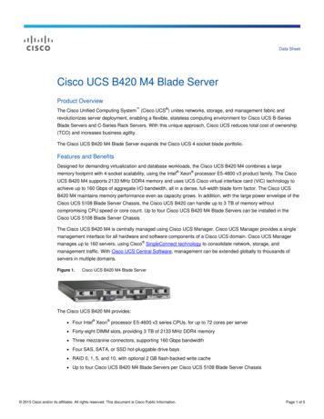
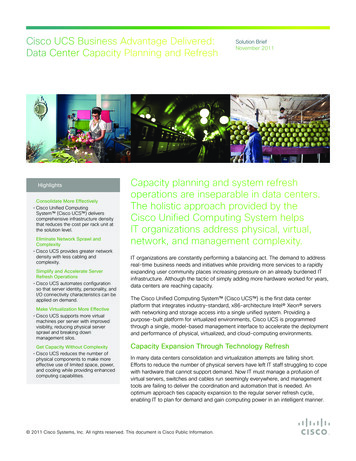
OVERVIEWOVERVIEWThe Cisco UCS C22 M3 small form factor (SFF) drive Rack Server combines economics and adensity-optimized feature set from entry level enterprise to SMB with applications such as scale out,virtualization, IT and web infrastructure, VPN servers, file/print servers, and appliances.Building on the success of the Cisco UCS C-Series Servers, the Cisco UCS C22 M3 server and the Cisco 1225VIC further extend the capabilities of the Cisco UCS portfolio in a 1RU form factor with the addition of theIntel Xeon E5-2400 v2 and E5-2400 series processor family CPUs, which delivers the best combination ofperformance and efficiency gains. In addition, the Cisco UCS C22 M3 server offers 12 DIMM slots, up to eightdisk drives, two PCIe slots and two 1 Gigabit Ethernet LAN-on-motherboard (LOM) ports that provide bothprice/performance in a compact 1U form factor.Figure 1Cisco UCS C22 M3 High-Density SFF Rack ServerFront ViewRear ViewCisco UCS C22 M3 High-Density SFF Rack-Mount Server3
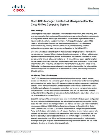
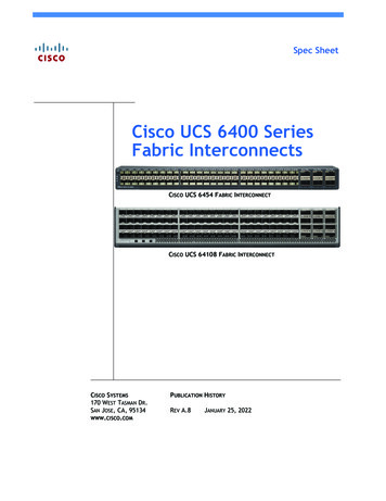
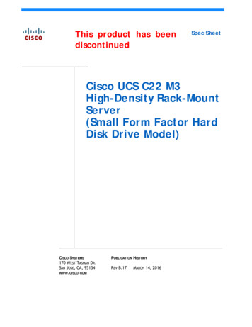
DETAILED VIEWSDETAILED VIEWSChassis Front ViewFigure 2 shows the Cisco UCS C22 M3 High-Density SFF Rack Server.1Chassis Front 08101Power button/power status LED6Power supply status LED2Identification button/LED7Network link activity LED3System status LED8USB 2.0 ports (two)4Fan status LED9Pull-out asset tag5Temperature status LED10Drives(up to eight hot-swappable 2-5-inch drives)4302158Figure 2Cisco UCS C22 M3 High-Density SFF Rack-Mount Server
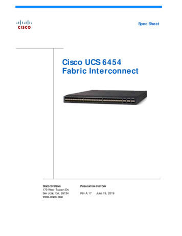
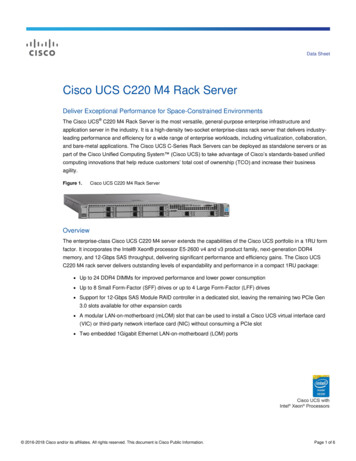
DETAILED VIEWSChassis Rear ViewFigure 3 shows the external features of the rear panel.Figure 3Chassis Rear View123PCIe 2PCIe 1302159PSU 14567891Power supply6Serial port (DB-9 connector)2Slot 2: Low-profile PCIe slot on riser 27VGA video port (DB-15 connector)810/100/1000 Base-T Ethernet dedicatedPCIe Gen 3 slot, x8, half-height, half-length3Slot 1: Standard-profile PCIe slot on riser 1PCIe Gen 3 slot, x16, full-height, half-lengthmanagement port4Dual 1-Gb Base-T Ethernet ports (two)9Rear Identification button/LED5USB 2.0 ports (four)——Cisco UCS C22 M3 High-Density SFF Rack-Mount Server5
BASE SERVER STANDARD CAPABILITIES and FEATURESBASE SERVER STANDARD CAPABILITIES and FEATURESTable 1 lists the capabilities and features of the base server. Details about how to configure the server fora particular feature or capability (for example, number of processors, disk drives, or amount of memory)are provided in CONFIGURING the SERVER, page 9.Table 1 Capabilities and FeaturesCapability/FeatureDescriptionChassisSingle rack unit (1RU) chassisCPUOne or two Intel Xeon E5-2400 v2 or E5-2400 series processor family CPUsChipsetIntel C600 chipsetMemory12 DIMM slotsNICEmbedded dual-port Intel I350 PCIe-based Gigabit Ethernet controllerExpansion slotsTwo riser cards with one PCIe card slot in each riser Riser 1 (controlled by CPU 1) Slot 1: PCIe Gen 3 slot, x16 extended connector (Cisco CNIC),half-length, full-height, with NCSI1 and Cisco CNIC2 support. TheCisco 1225 virtual interface card requires an NCSI slot. Riser 2 (controlled by CPU 2) Slot 2: PCIe Gen 3 slot, x8 connector, half-length, half-height, noNCSI supportInternal storage devicesVideo Up to eight 2.5-inch SAS SATA hot-swappable hard disk drives (HDDs) orsolid state drives (SSDs) One connector on the motherboard that can accommodate a USB 2.0drive. You can order an 8 or 16 GB drive for this connector and use it asa hypervisor or license dongle. The 8 or 16 GB USB drive comes blank.The Emulex Pilot 3 Integrated Baseboard Management Controller providesvideo: Matrox G200e video controller Integrated 2D graphics core with hardware acceleration 6Supports all display resolutions up to 1920 x 1200 x 16 bpp resolution at60 Hz 24-bit color depth for all resolutions less than 1600x1200 8 MB video memoryCisco UCS C22 M3 High-Density SFF Rack-Mount Server
BASE SERVER STANDARD CAPABILITIES and FEATURESCapability/FeatureDescriptionStorage controllerThe following RAID options are available: Embedded RAID (3 Gbps) (these implementations of RAID do notconsume a PCIe slot). Embedded SATA-only RAID controller, supporting up to four SATA-onlydrives (RAID 0, 1, 10), or ROM5 RAID upgrade, supporting up to eight SAS SATA drives (RAID 0,1, 10), or ROM55 RAID upgrade, supporting up to eight SAS SATA drives (RAID 0,1, 5, 10). PCIe RAID controllers (these consume PCIe slots) LSI MegaRAID 9270CV-8i with 1 GB Transportable Memory Module(TMM) data cache and chassis-mounted (remote) supercap for datacache power backup, supporting RAID 0, 1, 5, 6, 10, 50, and 60 andup to eight internal SAS SATA drives. LSI MegaRAID 9240-8i RAID 8-port PCIe RAID controller, supportingRAID 0, 1, 5, 10, and 50 and up to eight internal SAS SATA drives. LSI MegaRAID 9220-8i RAID 8-port PCIe RAID controller supportingRAID 0, 1, and 10 and up to eight internal SAS SATA drives.Interfaces Rear panel One DB9 serial port connector Four USB 2.0 port connectors One DB15 VGA connector One 10/100/1000 Ethernet management port Two 1 GbE (10/100/1000 Mbps capable) Ethernet LOM ports Front panel Two USB 2.0 portsFront PanelPower subsystem A front panel controller provides status indications and control buttonsOne 450 W power supply or one 650 W power supply, depending on serverconfiguration and loading. Prior to making a power supply selection, the UCSPower Calculator should be run to determine the right size power supply foryour server configuration. A fully configured C22 M3 server may require the650 W power supply. The UCS Power Calculator can be found at the ssis: Five fans for front-to-rear cooling. N 1 redundant.Power supply: The power supply is equipped with a fan.Cisco UCS C22 M3 High-Density SFF Rack-Mount Server7
BASE SERVER STANDARD CAPABILITIES and FEATURESCapability/FeatureDescriptionIntegrated managementprocessorCisco Integrated Management Controller (CIMC).Depending on your CIMC settings, the CIMC can be accessed through the 1-GbEthernet dedicated management port, the 1-Gb Ethernet LOM ports, or aCisco 1225 virtual interface card.Notes . . .1. NCSI network communications services interface protocol. The slot stays active when the server is in standbypower state.2. CNIC Cisco network interface card.8Cisco UCS C22 M3 High-Density SFF Rack-Mount Server
CONFIGURING the SERVERCONFIGURING the SERVERFollow these steps to configure the Cisco UCS C22 M3 High-Density SFF Rack Server: STEP 1 VERIFY SERVER SKU, page 10 STEP 2 SELECT CPU(s), page 11 STEP 3 SELECT MEMORY, page 13 STEP 4 SELECT RAID CONFIGURATION, page 17 STEP 5 SELECT DRIVES, page 22 STEP 6 SELECT PCIe OPTION CARD(s), page 24 STEP 7 ORDER OPTIONAL NETWORK CARD ACCESSORIES, page 25 STEP 8 SELECT AC POWER CORD(s), page 31 STEP 9 ORDER POWER SUPPLY, page 34 STEP 10 ORDER OPTIONAL REVERSIBLE CABLE MANAGEMENT ARM, page 35 STEP 11 ORDER A TRUSTED PLATFORM MODULE, page 36 STEP 12 ORDER OPTIONAL USB 2.0 DRIVE, page 37 STEP 13 SELECT OPERATING SYSTEM AND VALUE-ADDED SOFTWARE, page 38 STEP 14 SELECT OPERATING SYSTEM MEDIA KIT, page 41 STEP 15 SELECT SERVICE and SUPPORT LEVEL, page 42 OPTIONAL STEP - ORDER RACK(s), page 47 OPTIONAL STEP - ORDER PDU, page 48Cisco UCS C22 M3 High-Density SFF Rack-Mount Server9
CONFIGURING the SERVERSTEP 1VERIFY SERVER SKUVerify the product ID (PID) of the server as shown in Table 2.Table 2 PID of the C22 M3 High-Density SFF Rack Base ServerProduct ID (PID)UCSC-C22-M3SDescriptionUCS C22 M3 SFF with rail kit, without PSU, CPU, memory, HDD, SSD, or PCIecardsThe Cisco C22 M3 server: Includes a rail kit (UCSC-RAIL1) Does not include power supply, CPU, memory, hard disk drives (HDDs), solid state drives(SSDs), or plug-in PCIe cards.NOTE: Use the steps on the following pages to configure the server withthe components that you want to include.10Cisco UCS C22 M3 High-Density SFF Rack-Mount Server
CONFIGURING the SERVERSTEP 2SELECT CPU(s)The standard CPU features are: Intel Xeon E5-2400 v2 or E5-2400 series processor family CPUs Intel C600 chipset Cache size of up to 25 MBSelect CPUsThe available CPUs are listed in Table 3.Table 3 Available Intel CPUs: Xeon E5-24xx FamilyIntelNumberProduct ID T/s)Highest DDR3DIMM ClockSupport(MHz)1Intel Xeon E5-2400 v2UCS-CPU-E52470BE52470 v22.49525108.01600UCS-CPU-E52450BE52450 v22.5952088.01600UCS-CPU-E52440BE52440 v21.9952087.21600UCS-CPU-E52430BE52430 v22.5801567.21600UCS-CPU-E52430LBE52430L v22.4601567.21600UCS-CPU-E52420BE52420 v22.2801567.21600UCS-CPU-E52407BE52407 v22.4801046.41333UCS-CPU-E52403BE52403 E5-24031.80801046.41066Intel Xeon E5-2400Notes . . .1. If higher or lower speed DIMMs are selected than what is shown in the table for a given CPU, the DIMMs will beclocked at the lowest common denominator of CPU clock and DIMM clock.Cisco UCS C22 M3 High-Density SFF Rack-Mount Server11
CONFIGURING the SERVERApproved Configurations(1) 1-CPU configurations: Select any one CPU listed in Table 3.(2) 2-CPU Configurations: Select two identical CPUs from any one of the rows of Table 3 on page 11.Caveats12 You can select either one CPU or two identical CPUs. If you select one CPU, only one PCIe slot (the full-height slot on riser 1) is available for use. For optimal performance, select DIMMs with the highest clock speed for a given processor(see Table 3 on page 11). If you select DIMMs whose speeds are lower or higher than thatshown in the tables, suboptimal performance will result.Cisco UCS C22 M3 High-Density SFF Rack-Mount Server
CONFIGURING the SERVERSTEP 3SELECT MEMORYThe standard memory features are: Figure 4DIMMs—Clock speed: 1600 or 1333 MHz—Ranks per DIMM: 1, 2, or 4—Operational voltage: 1.35 V or 1.5 V—Registered ECC DDR3 DIMMS (RDIMMS), unregistered DIMMs (UDIMMs), orload-reduced DIMMs (LRDIMMs)Memory is organized with three memory channels per CPU, with up to two DIMMs perchannel, as shown in Figure 4.C22 M3 SFF Memory OrganizationCisco UCS C22 M3 High-Density SFF Rack-Mount Server13
CONFIGURING the SERVERSelect DIMMsSelect the memory configuration. The available memory DIMMs are listed in Table 4.NOTE: When memory mirroring is enabled, the memory subsystem simultaneouslywrites identical data to two channels. If a memory read from one of the channelsreturns incorrect data due to an uncorrectable memory error, the systemautomatically retrieves the data from the other channel. A transient or soft error inone channel does not affect the mirrored data, and operation continues unless thereis a simultaneous error in exactly the same location on a DIMM and its mirroredDIMM. Memory mirroring reduces the amount of memory available to the operatingsystem by 50% because only one of the two populated channels provides data.Table 4 Available DDR3 DIMMsPID DescriptionVoltageRanks/DIMMUCS-MR-1X041RY-A4GB DDR3-1600-MHz RDIMM/PC3-12800/1R/x4/1.35v1.35 V1UCS-MR-1X082RY-A8GB DDR3-1600-MHz RDIMM/PC3-12800/2R/x4/1.35v1.35 V2UCS-MR-1X162RY-A16GB DDR3-1600-MHz RDIMM/PC3-12800/2R/x4/1.35v1.35 V2UCS-ML-1X324RY-A32GB DDR3-1600-MHz LR DIMM/PC3-12800/4R/x4/1.35v1.35 V4Product ID (PID)DIMM OptionsMemory Mirroring OptionN01-MMIRROR14Memory mirroring optionCisco UCS C22 M3 High-Density SFF Rack-Mount Server
CONFIGURING the SERVERApproved Configurations(1) 1-CPU configuration without memory mirroring: Select from 1 to 6 DIMMs. Refer to Memory Population Rules, page 52, for more detailedinformation.(2) 1-CPU configuration with memory mirroring: Select either 2 or 4 DIMMs. The DIMMs will be placed by the factory as shown in the followingtable:Number ofDIMMs(Channel A is not used with memory mirroring)DIMM Placement in Channels2CPU 1: 1 DIMM in Channel B, 1 DIMM in Channel C4CPU 1: 2 DIMMs in Channel B, 2 DIMMs in Channel CSelect the memory mirroring option (N01-MMIRROR) as shown in Table 4 on page 14.(1) 2-CPU configuration without memory mirroring: Select from 1 to 6 DIMMs per CPU (2 to 12 DIMMs total). Refer to Memory Population Rules,page 52, for more detailed information.(2) 2-CPU configuration with memory mirroring: Select 2 or 4 DIMMs per CPU (4 or 8 DIMMs total). The DIMMs will be placed by the factory asshown in the following table:Number ofDIMMs perCPU DIMM Placement(Channels A and D are not used with memory mirroring)2CPU 1:1 DIMM in Channel B1 DIMM in Channel CCPU 2:1 DIMM in Channel E1 DIMM in channel F4CPU 1:2 DIMMs in Channel B2 DIMMs in Channel CCPU 2:2 DIMMs in Channel E2 DIMMs in Channel FSelect the memory mirroring option (N01-MMIRROR) as shown in Table 4 on page 14.NOTE: System performance is optimized when the DIMM type and quantity are equalfor both CPUs.Cisco UCS C22 M3 High-Density SFF Rack-Mount Server15
CONFIGURING the SERVERCaveats Do not mix 1333 MHz and 1600 MHz DIMMs Do not mix DIMM types (RDIMM, LRDIMM, or UDIMM) Do not select more than two different types of DIMMs (only two PID types allowed) For 2-CPU configurations, install a minimum of 2 DIMMs (one per CPU). If you use different sizes of DIMMs, the quantity of each size of DIMM must be even (2, 4, or6). For example, 4 UCS-MR-1X082RY-A DIMMs and 6 UCS-MR-1X162RY-A DIMMs. Also, the sumof all PIDs must adhere to the maximum quantity rule of 12 DIMMs for 2-CPU systems. By default, all DIMMs run at 1.35 V, which yields 1333-MHz memory speeds. To run thememory DIMMS at 1600 MHz, you need to go into the BIOS or set the policy with UCSM(service profile) to run in Performance Mode. This forces the DIMMs to operate at 1.5 V andyields 1600-MHz speeds, provided:—The DIMMs are 1600-MHz devices—The CPUs chosen support 1600-MHz operation.NOTE: 32 GB LRDIMMs run at a maximum speed of 1333 MHz for 1 DPC and 2 DPCeven though their specified maximum speed is 1600 MHz.NOTE: In this server, 4 GB UDIMMs run slower than their specified maximum speed of1600 MHz. In addition, the following rules apply to UDIMMs: 1 DPC: 1333 MHz is supported at 1.35 V and 1.5 V 2 DPC: 1066 MHz is supported at 1.35 V and 1.5 VFor more information regarding memory, see CPUs and DIMMs, page 50.16Cisco UCS C22 M3 High-Density SFF Rack-Mount Server
CONFIGURING the SERVERSTEP 4SELECT RAID CONFIGURATIONNOTE: If you do not select a PCIe RAID controller or one of the embedded RAIDupgrade options, you will have an embedded SATA-only RAID controller that supportsup to four SATA-only drives (RAID 0, 1, 10)NOTE: When creating a RAID volume, follow these guidelines: Use the same capacity for each drive in the volume Use either all SAS drives or all SATA drives Use either all HDDs or all SSDsNOTE: The number of RAID groups (virtual drives) supported per controller is asfollows (note however, that this server can have a maximum of only eight internalphysical drives): LSI MegaRAID SAS 9270CV-8i RAID controller card 64 LSI MegaRAID 9240-8i RAID controller card 16 LSI MegaRAID 9220-8i RAID controller card 16The RAID controller choices are:(1) Embedded RAID (on motherboard)\NOTE: Embedded RAID is not available with VMWare.NOTE: The RAID configuration options listed in Table 6 on page 18 are not availableif you choose embedded RAID (in this case, you must configure RAID yourself usingseparate software).(2) PCIe RAID controllersCisco can provide factory-configured RAID systems depending on the RAID controller chosen andthe number of drives ordered. Factory-configured RAID options are listed with each RAID carddescription.RAID levels 50 and 60 are supported, although they are not available as factory-configured RAIDoptions.Cisco UCS C22 M3 High-Density SFF Rack-Mount Server17
CONFIGURING the SERVERSelect RAID OptionsSelect one RAID controller (either embedded RAID in Table 5 or hardware RAID using a PCIe RAIDcontroller and an appropriate RAID configuration option listed in Table 6 on page 18).Table 5 Available Embedded RAID (LSI MegaSR) OptionsProduct ID (PID)PID DescriptionEmbedded RAIDUCSC-RAID-ROM5Onboard RAID, consisting of a plug-in storage controller unit (SCU), supportingup to 8 internal SAS SATA drives. SAS and SATA drives can be mixed. This optionsupports RAID 0, 1, and 10, and operates at 3 Gb/s. Operating systemssupported are Windows and Linux only (no VMware support).UCSC-RAID-ROM55Onboard RAID, consisting of two plug-in modules (an SCU plus a software keymodule) supporting up to 8 internal SAS SATA drives. SAS and SATA drives can bemixed. This option supports RAID 0, 1, 5, and 10 and operates at 3 Gb/s.Operating systems supported are Windows and Linux only (no VMware support).NOTE: VMware ESX/ESXi or any other virtualized environments are not supportedfor use with the embedded MegaRAID controller. Hypervisors such as Hyper-V, Xen, orKVM are also not supported for use with the embedded MegaRAID controllerTable 6 Available Hardware RAID OptionsProduct ID (PID)PID DescriptionRAID ControllersNote that PCIe RAID controllers are installed by default in slot 1 for 1-CPU systems and slot 2 for2-CPU systemsUCSC-RAID-9240-8IUCSC-RAID-9220-8I18LSI MegaRAID 9240-8i Supports up to 8 internal SAS SATA drives. SAS and SATA drives can bemixed. RAID levels supported: RAID 0, 1, 5, 10, 50 (see the RAID ConfigurationOptions section later in this table)LSI MegaRAID 9220-8i Supports up to 8 internal SAS SATA drives. SAS and SATA drives can bemixed. RAID levels supported: RAID 0, 1, 10 (see the RAID Configuration Optionssection later in this table)Cisco UCS C22 M3 High-Density SFF Rack-Mount Server
CONFIGURING the SERVERTable 6 Available Hardware RAID Options (continued)Product ID (PID)PID DescriptionUCS-RAID9270CV-8iLSI MegaRAID 9270CV-8i (with supercap power backup) Supports up to 8 internal SAS SATA drives. SAS and SATA drives can bemixed. Includes a 1 GB Transportable Memory Module (TMM) cache andchassis-mount (remote) supercap power module for data cache backup RAID levels supported: RAID 0, 1, 5, 6, 10, 50, 60 (see the RAIDConfiguration Options section later in this table)RAID Configuration Options (not available for embedded RAID)R2XX-RAID0Factory preconfigured RAID striping optionEnable RAID 0 Setting. Requires a minimum of one hard drive.R2XX-RAID1Factory preconfigured RAID mirroring optionEnable RAID 1 Setting. Requires exactly two drives with the same size, speed,capacity.R2XX-RAID5Factory preconfigured RAID optionEnable RAID 5 Setting. Requires a minimum of three drives of the same size,speed, capacity.R2XX-RAID6Factory preconfigured RAID optionEnable RAID 6 Setting. Requires a minimum of four drives of the same size,speed, capacity.R2XX-RAID10Factory preconfigured RAID optionEnable RAID 10 Setting. Requires an even number of drives (minimum of fourdrives) of the same size, speed, capacity.NOTE: Although RAID levels 50 and 60 are not orderable from the factory, they aresupported for selected controllers as shown in Table 6.Cisco UCS C22 M3 High-Density SFF Rack-Mount Server19
CONFIGURING the SERVERApproved Configurations(1) 1-CPU ConfigurationsSelect an embedded RAID option from Table 5 on page 18 or one PCIe RAID controller fromTable 6 on page 18. You may also select an appropriate optional RAID configuration listed inTable 6 on page 18.NOTE: In 1-CPU configurations, PCIe slot 1 is the default slot supported for aninternal drive RAID controller. PCIe slot 2 is not supported for 1-CPU systems.NOTE: If you do not select a PCIe RAID controller or one of the embedded RAIDupgrade options from Table 5 on page 18, you will have an embedded SATA-onlyRAID controller that supports up to four SATA-only drives (RAID 0, 1, 10) and slot 1can be used for a PCIe RAID controller (see Table 8 on page 24).(2) 2-CPU ConfigurationsSelect an embedded RAID option from Table 5 on page 18, or one PCIe RAID controller fromTable 6 on page 18. You may also select an appropriate optional RAID configuration listed inTable 6 on page 18.NOTE: In 2-CPU configurations, PCIe slot 2 is the default slot supported for aninternal drive RAID controller. PCIe slot 1 can be used for a PCIe expansion card(including the VIC card). You can change the default card slot for a RAID controller toslot 1 by going into the BIOS and reconfiguring the option ROM (OPROM) settings.Keep in mind, however, that if you use slot 1 for a RAID controller, you will not beable to install a VIC card, which can be installed only in slot 1.NOTE: If you do not select a PCIe RAID controller, or one of the embedded RAIDupgrade options from Table 5 on page 18, you will have an embedded SATA-onlyRAID controller that supports up to four SATA-only drives (RAID 0, 1, 10) and slots 1and 2 can be used for PCIe cards (see Table 8 on page 24).Caveats 20In 1-CPU configurations, there is only one full-height PCIe slot available (located on riser 1).Slot 2 is not supported in 1-CPU systems.—If you choose embedded RAID, you can select one optional PCIe card from Table 8on page 24 to be installed in slot 1.—If you choose a PCIe RAID controller from Table 5 on page 18, it will be installed inslot 1 by default and you will not be able to select any optional PCIe card fromTable 8 on page 24.Cisco UCS C22 M3 High-Density SFF Rack-Mount Server
CONFIGURING the SERVER —Note that only a single Cisco 1225 Virtual Interface Card (VIC) card is supported andit must be installed in the full-length, full-height PCIe slot (slot 1) on riser 1, whichis the only slot that supports NCSI. So take this into account when populating RAIDcontroller cards. You can have either a PCIe RAID controller or a VIC card in slot 1.—Slot 2 is not supported in 1-CPU systems.In 2-CPU configurations, there are two PCIe slots available (one full-height slot, slot 1, andone half-height slot, slot 2).—If you choose embedded RAID, you can select up to two optional PCIe cards fromTable 8 on page 24 to be installed in slots 1 and 2.—If you choose a PCIe RAID controller from Table 5 on page 18, it will be installed inslot 2 by default and you will be able to select one additional optional PCIe cardfrom Table 8 on page 24 to be installed in slot 1. The optional PCIe RAID controllers are all half-height. If you choose one of these cards in a2-CPU configuration, only the full-height PCIe card slot will be available for an additionaloptional PCIe card. Note that only a single Cisco UCS 1225 Virtual Interface Card (VIC) card is supported and itmust be installed in the full-length, full-height PCIe slot (slot 1) on riser 1, which is the onlyslot that supports NCSI. So take this into account when populating RAID controller cards. You can choose only one type of RAID controller, either embedded RAID or a PCIe RAIDcontroller. If you choose embedded RAID, slot 1 in a 1-CPU system and slots 1 and 2 in a2-CPU system are available for adding optional PCIe cards. For PCIe RAID controllers, you can choose an optional RAID configuration (RAID 0, 1, 5, 6, or10), which is preconfigured at the factory. The RAID level you choose must be an availableRAID choice for the controller selected. RAID levels 50 and 60 are supported, depending onthe RAID controller selected, although they are not available as configuration options.NOTE: For more important information regarding RAID support, see RAID Summary,page 56 and RAID Option ROM (OPROM) Settings, page 57.Cisco UCS C22 M3 High-Density SFF Rack-Mount Server21
CONFIGURING the SERVERSTEP 5SELECT DRIVESThe standard disk drive features are: 2.5-inch small form factor Hot-pluggable Sled-mountedSelect DrivesThe available drives are listed in Table 7.Table 7 Available Hot-Pluggable Sled-Mounted HDDs or SSDsPID DescriptionDriveTypeCapacityUCS-HDD250G1F111250 GB 6Gb SATA 7.2K RPMSATA250 GBUCS-HDD300GI2F105300 GB 6Gb SAS 15K RPM SFFSAS300 GBA03-D300GA2300 GB 6Gb SAS 10K RPM SFFSAS300 GBA03-D500GC3500 GB SATA 7.2K RPM SFFSATA500 GBA03-D600GA2600 GB 6Gb SAS 10K RPM SFFSAS600 GBUCS-HDD900GI2F106900 GB 6Gb SAS 10K RPM SFFSAS600 GBA03-D1TBSATA1 TB SATA 7.2K RPM SFFSATA1 TBUCS-SD200G0KS2-EP200 GB 2.5 inch Enterprise Performance SASSAS200 GBUCS-SD400G0KS2-EP400 GB 2.5 inch Enterprise Performance SASSAS400 GBUCS-SD800G0KS2-EP800 GB 2.5 inch Enterprise Performance SASSAS800 GBUCS-SD480G0KS2-EV480 GB 2.5 inch Enterprise Value 6 G SATA SSDSATA480 GBUCS-SD240G0KS2-EV240 GB 2.5 inch Enterprise Value 6 G SATA SSDSATA240 GBUCS-SD120G0KS2-EV120 GB 2.5 inch Enterprise Value 6 G SATA SSDSATA120 GBUCS-SD100G0KA2-G100 GB Read SSDSATA100 GBUCS-SD400G0KA2-G400 GB Read SSDSATA400 GBProduct ID (PID)HDDsSSDs22Cisco UCS C22 M3 High-Density SFF Rack-Mount Server
CONFIGURING the SERVERNOTE: When creating a RAID volume, follow these guidelines: Use the same capacity for each drive in the volume Use either all SAS drives or all SATA drives Use either all HDDs or all SSDsNOTE: The number of RAID groups (virtual drives) supported per controller is asfollows: LSI MegaRAID SAS 9270CV-8i RAID controller card
Power subsystem One 450 W power supply or one 650 W power supply, depending on server configuration and loading. Prior to ma king a power supply selection, the UCS Power Calculator should be run to determine the right size power supply for your server configuration. A fully configured C22 M3 server may require the 650 W power supply.