Transcription
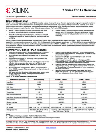
197 Series FPGAs Data Sheet: OverviewDS180 (v2.6.1) September 8, 2020Product SpecificationGeneral DescriptionXilinx 7 series FPGAs comprise four FPGA families that address the complete range of system requirements, ranging from low cost, small form factor,cost-sensitive, high-volume applications to ultra high-end connectivity bandwidth, logic capacity, and signal processing capability for the most demandinghigh-performance applications. The 7 series FPGAs include: Spartan -7 Family: Optimized for low cost, lowest power, and highI/O performance. Available in low-cost, very small form-factorpackaging for smallest PCB footprint. Kintex -7 Family: Optimized for best price-performance with a 2Ximprovement compared to previous generation, enabling a new classof FPGAs. Artix -7 Family: Optimized for low power applications requiring serialtransceivers and high DSP and logic throughput. Provides the lowesttotal bill of materials cost for high-throughput, cost-sensitiveapplications. Virtex -7 Family: Optimized for highest system performance andcapacity with a 2X improvement in system performance. Highestcapability devices enabled by stacked silicon interconnect (SSI)technology.Built on a state-of-the-art, high-performance, low-power (HPL), 28 nm, high-k metal gate (HKMG) process technology, 7 series FPGAs enable anunparalleled increase in system performance with 2.9 Tb/s of I/O bandwidth, 2 million logic cell capacity, and 5.3 TMAC/s DSP, while consuming 50% lesspower than previous generation devices to offer a fully programmable alternative to ASSPs and ASICs.Summary of 7 Series FPGA Features Advanced high-performance FPGA logic based on real 6-input lookup table (LUT) technology configurable as distributed memory.36 Kb dual-port block RAM with built-in FIFO logic for on-chip databuffering.High-performance SelectIO technology with support for DDR3interfaces up to 1,866 Mb/s.High-speed serial connectivity with built-in multi-gigabit transceiversfrom 600 Mb/s to max. rates of 6.6 Gb/s up to 28.05 Gb/s, offering aspecial low-power mode, optimized for chip-to-chip interfaces.A user configurable analog interface (XADC), incorporating dual12-bit 1MSPS analog-to-digital converters with on-chip thermal andsupply sensors.DSP slices with 25 x 18 multiplier, 48-bit accumulator, and pre-adderfor high-performance filtering, including optimized symmetriccoefficient filtering. Powerful clock management tiles (CMT), combining phase-lockedloop (PLL) and mixed-mode clock manager (MMCM) blocks for highprecision and low jitter.Quickly deploy embedded processing with MicroBlaze processor.Integrated block for PCI Express (PCIe), for up to x8 Gen3Endpoint and Root Port designs.Wide variety of configuration options, including support forcommodity memories, 256-bit AES encryption with HMAC/SHA-256authentication, and built-in SEU detection and correction.Low-cost, wire-bond, bare-die flip-chip, and high signal integrity flipchip packaging offering easy migration between family members inthe same package. All packages available in Pb-free and selectedpackages in Pb option.Designed for high performance and lowest power with 28 nm,HKMG, HPL process, 1.0V core voltage process technology and0.9V core voltage option for even lower power.Table 1: 7 Series Families ComparisonMax. CapabilityLogic CellsBlock RAM(1)DSP SlicesDSPPerformance(2)MicroBlaze 1,955K4.2 Mb13 Mb34 Mb68 Mb1607401,9203,600176 GMAC/s929 GMAC/s2,845 GMAC/s5,335 GMAC/s260 DMIPs303 DMIPs438 DMIPs441 DMIPsTransceivers–163296Transceiver Speed–6.6 Gb/s12.5 Gb/s28.05 Gb/sSerial Bandwidth–211 Gb/s800 Gb/s2,784 Gb/sPCIe Interface–x4 Gen2x8 Gen2x8 Gen3800 Mb/s1,066 Mb/s1,866 Mb/s1,866 Mb/sMemory InterfaceI/O PinsI/O VoltagePackage 3.3V1.2V–3.3VLow-Cost, Wire-BondLow-Cost, Wire-Bond,Bare-Die Flip-ChipBare-Die Flip-Chip and HighPerformance Flip-ChipHighest PerformanceFlip-ChipNotes:1.2.3.Additional memory available in the form of distributed RAM.Peak DSP performance numbers are based on symmetrical filter implementation.Peak MicroBlaze CPU performance numbers based on microcontroller preset. Copyright 2010–2020 Xilinx, Inc. Xilinx, the Xilinx logo, Alveo, Artix, Kintex, Spartan, UltraScale, Versal, Virtex, Vivado, Zynq, and other designated brands included hereinare trademarks of Xilinx in the United States and other countries. PCI, PCI Express, PCIe, and PCI-X are trademarks of PCI-SIG. All other trademarks are the property of theirrespective owners.DS180 (v2.6.1) September 8, 2020Product Specificationwww.xilinx.com1
7 Series FPGAs Data Sheet: OverviewSpartan-7 FPGA Feature SummaryTable 2: Spartan-7 FPGA Feature Summary by DeviceBlock RAM dRAM (Kb)DSPSlices(2)18 Kb36 KbMax(Kb)180CMTs(4)PCIeGTXADCBlocksTotal I/OBanks(5)Max .3.4.5.Each 7 series FPGA slice contains four LUTs and eight flip-flops; only some slices can use their LUTs as distributed RAM or SRLs.Each DSP slice contains a pre-adder, a 25 x 18 multiplier, an adder, and an accumulator.Block RAMs are fundamentally 36 Kb in size; each block can also be used as two independent 18 Kb blocks.Each CMT contains one MMCM and one PLL.Does not include configuration Bank 0.Table 3: Spartan-7 FPGA Device-Package Combinations and Maximum 676Size (mm)8x813 x 1315 x 1515 x 1523 x 2327 x 27Ball Pitch 100XC7S25XC7S50HRI/O(1)HRI/O(1)100HRI/O(1)HR 400XC7S100338400Notes:1.HR High-range I/O with support for I/O voltage from 1.2V to 3.3V.DS180 (v2.6.1) September 8, 2020Product Specificationwww.xilinx.com2
7 Series FPGAs Data Sheet: OverviewArtix-7 FPGA Feature SummaryTable 4: Artix-7 FPGA Feature Summary by DeviceConfigurable Logic dRAM (Kb)Block RAM Blocks(3)DSP48E1Slices(2)18 Kb36 KbMax(Kb)CMTs(4)PCIe(5)GTPsXADCBlocksTotal I/OBanks(6)Max 500Notes:1.Each 7 series FPGA slice contains four LUTs and eight flip-flops; only some slices can use their LUTs as distributed RAM or SRLs.2.Each DSP slice contains a pre-adder, a 25 x 18 multiplier, an adder, and an accumulator.3.Block RAMs are fundamentally 36 Kb in size; each block can also be used as two independent 18 Kb blocks.4.Each CMT contains one MMCM and one PLL.5.Artix-7 FPGA Interface Blocks for PCI Express support up to x4 Gen 2.6.Does not include configuration Bank 0.7.This number does not include GTP transceivers.Table 5: Artix-7 FPGA Device-Package Combinations and Maximum FGG484(2)Size (mm)10 x 1010 x 1015 x 1515 x 1517 x 1719 x 1923 x 2323 x 2327 x 2727 x 2735 x 35Ball R(5)500Notes:1.All packages listed are Pb-free (SBG, FBG, FFG with exemption 15). Some packages are available in Pb option.2.Devices in FGG484 and FBG484 are footprint compatible.3.Devices in FGG676 and FBG676 are footprint compatible.4.GTP transceivers in CP, CS, FT, and FG packages support data rates up to 6.25 Gb/s.5.HR High-range I/O with support for I/O voltage from 1.2V to 3.3V.DS180 (v2.6.1) September 8, 2020Product Specificationwww.xilinx.com3
7 Series FPGAs Data Sheet: OverviewKintex-7 FPGA Feature SummaryTable 6: Kintex-7 FPGA Feature Summary by DeviceConfigurable LogicBlocks (CLBs)DeviceLogicCellsBlock RAM Blocks(3)MaxDistributedRAM (Kb)Slices(1)DSPSlices(2)CMTs(4)18 Kb36 KbPCIe(5)GTXsXADCBlocksTotal I/OBanks(6)Max 881,9201,91095534,380813218400Notes:1.Each 7 series FPGA slice contains four LUTs and eight flip-flops; only some slices can use their LUTs as distributed RAM or SRLs.2.Each DSP slice contains a pre-adder, a 25 x 18 multiplier, an adder, and an accumulator.3.Block RAMs are fundamentally 36 Kb in size; each block can also be used as two independent 18 Kb blocks.4.Each CMT contains one MMCM and one PLL.5.Kintex-7 FPGA Interface Blocks for PCI Express support up to x8 Gen 2.6.Does not include configuration Bank 0.7.This number does not include GTX transceivers.Table 7: Kintex-7 FPGA Device-Package Combinations and Maximum I/OsPackage(1)FBG484FBG676(2)FFG676(2)Size (mm)23 x 2327 x 27Ball Pitch(mm)1.01.0DeviceI/OGTX(4)I/OGTXHR(5) HP(6)(4)HR(5) HP(6)GTXFBG900(3)FFG900(3)FFG901FFG115627 x 2731 x 3131 x 3131 x 3135 x 351.01.01.01.01.0I/OI/OGTXHR(5) HP(6)(4)HR(5) HP(6)GTXI/OHR(5) 635015016350150XC7K325TXC7K355TGTXI/OHR(5) HP(6)GTXI/OHR(5) 0XC7K410TNotes:1.All packages listed are Pb-free (FBG, FFG with exemption 15). Some packages are available in Pb option.2.Devices in FBG676 and FFG676 are footprint compatible.3.Devices in FBG900 and FFG900 are footprint compatible.4.GTX transceivers in FB packages support the following maximum data rates: 10.3Gb/s in FBG484; 6.6Gb/s in FBG676 and FBG900. Refer to Kintex-7 FPGAs Data Sheet:DC and AC Switching Characteristics (DS182) for details.5.HR High-range I/O with support for I/O voltage from 1.2V to 3.3V.6.HP High-performance I/O with support for I/O voltage from 1.2V to 1.8V.DS180 (v2.6.1) September 8, 2020Product Specificationwww.xilinx.com4
7 Series FPGAs Data Sheet: OverviewVirtex-7 FPGA Feature SummaryTable 8: Virtex-7 FPGA Feature SummaryConfigurable LogicBlocks (CLBs)DeviceLogicCellsSlices(1)MaxDistributedRAM (Kb)Block RAM Blocks(3)DSPSlices(2)18 Kb36 KbMax(Kb)CMTsPCIe(5)GTXGTHGTZXADCBlocksTotal Each 7 series FPGA slice contains four LUTs and eight flip-flops; only some slices can use their LUTs as distributed RAM or SRLs.2.Each DSP slice contains a pre-adder, a 25 x 18 multiplier, an adder, and an accumulator.3.Block RAMs are fundamentally 36 Kb in size; each block can also be used as two independent 18 Kb blocks.4.Each CMT contains one MMCM and one PLL.5.Virtex-7 T FPGA Interface Blocks for PCI Express support up to x8 Gen 2. Virtex-7 XT and Virtex-7 HT Interface Blocks for PCI Express support up to x8 Gen 3, with theexception of the XC7VX485T device, which supports x8 Gen 2.6.Does not include configuration Bank 0.7.This number does not include GTX, GTH, or GTZ transceivers.8.Super logic regions (SLRs) are the constituent parts of FPGAs that use SSI technology. Virtex-7 HT devices use SSI technology to connect SLRs with 28.05 Gb/stransceivers.DS180 (v2.6.1) September 8, 2020Product Specificationwww.xilinx.com5
7 Series FPGAs Data Sheet: OverviewTable 9: Virtex-7 FPGA Device-Package Combinations and Maximum ze (mm)35 x 3542.5 x 42.545 x 4545 x 45Ball Pitch1.01.01.0I/ODeviceXC7V585TGTXGTH200HR(3) 80TXC7VX1140TNotes:1.All packages listed are Pb-free (FFG, FHG, FLG with exemption 15). Some packages are available in Pb option.2.Devices in FFG1761 and FHG1761 are footprint compatible.3.HR High-range I/O with support for I/O voltage from 1.2V to 3.3V.4.HP High-performance I/O with support for I/O voltage from 1.2V to 1.8V.Table 10: Virtex-7 FPGA Device-Package Combinations and Maximum I/Os - 927FFG1928(3)FLG1928(3)FFG1930(4)FLG1930(4)Size (mm)35 x 3545 x 4545 x 4545 x 4545 x 4545 x 4545 x 4545 x 45Ball Pitch1.01.01.01.01.01.01.0I/ODeviceGTX GTHHPI/OGTX GTH(5)HPI/OGTX GTH(5)HPI/OGTX GTH(5)HPI/OGTX GTH(5)HPI/OGTX GTH(5)HP1.0I/OGTX GTH(5)HPI/OGTX tes:1.All packages listed are Pb-free (FFG, FLG with exemption 15). Some packages are available in Pb option.2.Devices in FFG1926 and FLG1926 are footprint compatible.3.Devices in FFG1928 and FLG1928 are footprint compatible.4.Devices in FFG1930 and FLG1930 are footprint compatible.5.HP High-performance I/O with support for I/O voltage from 1.2V to 1.8V.DS180 (v2.6.1) September 8, 2020Product Specificationwww.xilinx.com6
7 Series FPGAs Data Sheet: OverviewTable 11: Virtex-7 HT FPGA Device-Package Combinations and Maximum I/OsPackage(1)FLG1155FLG1931FLG1932Size (mm)35 x 3545 x 4545 x 45Ball otes:1.All packages listed are Pb-free with exemption 15. Some packages are available in Pb option.2.HP High-performance I/O with support for I/O voltage from 1.2V to 1.8V.Stacked Silicon Interconnect (SSI) TechnologyThere are many challenges associated with creating high capacity FPGAs that Xilinx addresses with the SSI technology.SSI technology enables multiple super logic regions (SLRs) to be combined on a passive interposer layer, using provenmanufacturing and assembly techniques from industry leaders, to create a single FPGA with more than ten thousand interSLR connections, providing ultra-high bandwidth connectivity with low latency and low power consumption. There are twotypes of SLRs used in Virtex-7 FPGAs: a logic intensive SLR used in the Virtex-7 T devices and a DSP/blockRAM/transceiver-rich SLR used in the Virtex-7 XT and HT devices. SSI technology enables the production of highercapability FPGAs than traditional manufacturing methods, enabling the highest capacity and highest performance FPGAsever created to reach production more quickly and with less risk than would otherwise be possible. Thousands of super longline (SLL) routing resources and ultra-high performance clock lines that cross between the SLRs ensure that designs spanseamlessly across these high-density programmable logic devices.CLBs, Slices, and LUTsSome key features of the CLB architecture include: Real 6-input look-up tables (LUTs) Memory capability within the LUT Register and shift register functionalityThe LUTs in 7 series FPGAs can be configured as either one 6-input LUT (64-bit ROMs) with one output, or as two 5-inputLUTs (32-bit ROMs) with separate outputs but common addresses or logic inputs. Each LUT output can optionally beregistered in a flip-flop. Four such LUTs and their eight flip-flops as well as multiplexers and arithmetic carry logic form aslice, and two slices form a configurable logic block (CLB). Four of the eight flip-flops per slice (one per LUT) can optionallybe configured as latches.Between 25–50% of all slices can also use their LUTs as distributed 64-bit RAM or as 32-bit shift registers (SRL32) or as twoSRL16s. Modern synthesis tools take advantage of these highly efficient logic, arithmetic, and memory features.Clock ManagementSome of the key highlights of the clock management architecture include: High-speed buffers and routing for low-skew clock distribution Frequency synthesis and phase shifting Low-jitter clock generation and jitter filteringEach 7 series FPGA has up to 24 clock management tiles (CMTs), each consisting of one mixed-mode clock manager(MMCM) and one phase-locked loop (PLL).DS180 (v2.6.1) September 8, 2020Product Specificationwww.xilinx.com7
7 Series FPGAs Data Sheet: OverviewMixed-Mode Clock Manager and Phase-Locked LoopThe MMCM and PLL share many characteristics. Both can serve as a frequency synthesizer for a wide range of frequenciesand as a jitter filter for incoming clocks. At the center of both components is a voltage-controlled oscillator (VCO), whichspeeds up and slows down depending on the input voltage it receives from the phase frequency detector (PFD).There are three sets of programmable frequency dividers: D, M, and O. The pre-divider D (programmable by configurationand afterwards via DRP) reduces the input frequency and feeds one input of the traditional PLL phase/frequencycomparator. The feedback divider M (programmable by configuration and afterwards via DRP) acts as a multiplier becauseit divides the VCO output frequency before feeding the other input of the phase comparator. D and M must be chosenappropriately to keep the VCO within its specified frequency range. The VCO has eight equally-spaced output phases(0 , 45 , 90 , 135 , 180 , 225 , 270 , and 315 ). Each can be selected to drive one of the output dividers (six for the PLL,O0 to O5, and seven for the MMCM, O0 to O6), each programmable by configuration to divide by any integer from 1 to 128.The MMCM and PLL have three input-jitter filter options: low bandwidth, high bandwidth, or optimized mode. Low-bandwidthmode has the best jitter attenuation but not the smallest phase offset. High-bandwidth mode has the best phase offset, butnot the best jitter attenuation. Optimized mode allows the tools to find the best setting.MMCM Additional Programmable FeaturesThe MMCM can have a fractional counter in either the feedback path (acting as a multiplier) or in one output path. Fractionalcounters allow non-integer increments of 1/8 and can thus increase frequency synthesis capabilities by a factor of 8.The MMCM can also provide fixed or dynamic phase shift in small increments that depend on the VCO frequency. At1600 MHz, the phase-shift timing increment is 11.2 ps.Clock DistributionEach 7 series FPGA provides six different types of clock lines (BUFG, BUFR, BUFIO, BUFH, BUFMR, and the highperformance clock) to address the different clocking requirements of high fanout, short propagation delay, and extremely lowskew.Global Clock LinesIn each 7 series FPGA (except XC7S6 and XC7S15), 32 global clock lines have the highest fanout and can reach every flipflop clock, clock enable, and set/reset, as well as many logic inputs. There are 12 global clock lines within any clock regiondriven by the horizontal clock buffers (BUFH). Each BUFH can be independently enabled/disabled, allowing for clocks to beturned off within a region, thereby offering fine-grain control over which clock regions consume power. Global clock lines canbe driven by global clock buffers, which can also perform glitchless clock multiplexing and clock enable functions. Globalclocks are often driven from the CMT, which can completely eliminate the basic clock distribution delay.Regional ClocksRegional clocks can drive all clock destinations in their region. A region is defined as an area that is 50 I/O and 50 CLB highand half the chip wide. 7 series FPGAs have between two and twenty-four regions. There are four regional clock tracks inevery region. Each regional clock buffer can be driven from any of four clock-capable input pins, and its frequency canoptionally be divided by any integer from 1 to 8.I/O ClocksI/O clocks are especially fast and serve only I/O logic and serializer/deserializer (SerDes) circuits, as described in theI/O Logic section. The 7 series devices have a direct connection from the MMCM to the I/O for low-jitter, high-performanceinterfaces.DS180 (v2.6.1) September 8, 2020Product Specificationwww.xilinx.com8
7 Series FPGAs Data Sheet: OverviewBlock RAMSome of the key features of the block RAM include: Dual-port 36 Kb block RAM with port widths of up to 72 Programmable FIFO logic Built-in optional error correction circuitryEvery 7 series FPGA has between 5 and 1,880 dual-port block RAMs, each storing 36 Kb. Each block RAM has twocompletely independent ports that share nothing but the stored data.Synchronous OperationEach memory access, read or write, is controlled by the clock. All inputs, data, address, clock enables, and write enables areregistered. Nothing happens without a clock. The input address is always clocked, retaining data until the next operation. Anoptional output data pipeline register allows higher clock rates at the cost of an extra cycle of latency.During a write operation, the data output can reflect either the previously stored data, the newly written data, or can remainunchanged.Programmable Data WidthEach port can be configured as 32K 1, 16K 2, 8K 4, 4K 9 (or 8), 2K 18 (or 16), 1K 36 (or 32), or 512 72 (or 64).The two ports can have different aspect ratios without any constraints.Each block RAM can be divided into two completely independent 18 Kb block RAMs that can each be configured to anyaspect ratio from 16K 1 to 512 36. Everything described previously for the full 36 Kb block RAM also applies to each ofthe smaller 18 Kb block RAMs.Only in simple dual-port (SDP) mode can data widths of greater than 18 bits (18 Kb RAM) or 36 bits (36 Kb RAM) beaccessed. In this mode, one port is dedicated to read operation, the other to write operation. In SDP mode, one side (reador write) can be variable, while the other is fixed to 32/36 or 64/72.Both sides of the dual-port 36 Kb RAM can be of variable width.Two adjacent 36 Kb block RAMs can be configured as one cascaded 64K 1 dual-port RAM without any additional logic.Error Detection and CorrectionEach 64-bit-wide block RAM can generate, store, and utilize eight additional Hamming code bits and perform single-bit errorcorrection and double-bit error detection (ECC) during the read process. The ECC logic can also be used when writing to orreading from external 64- to 72-bit-wide memories.FIFO ControllerThe built-in FIFO controller for single-clock (synchronous) or dual-clock (asynchronous or multirate) operation incrementsthe internal addresses and provides four handshaking flags: full, empty, almost full, and almost empty. The almost full andalmost empty flags are freely programmable. Similar to the block RAM, the FIFO width and depth are programmable, but thewrite and read ports always have identical width.First word fall-through mode presents the first-written word on the data output even before the first read operation. After thefirst word has been read, there is no difference between this mode and the standard mode.DS180 (v2.6.1) September 8, 2020Product Specificationwww.xilinx.com9
7 Series FPGAs Data Sheet: OverviewDigital Signal Processing — DSP SliceSome highlights of the DSP functionality include: 25 18 two's complement multiplier/accumulator high-resolution (48 bit) signal processor Power saving pre-adder to optimize symmetrical filter applications Advanced features: optional pipelining, optional ALU, and dedicated buses for cascadingDSP applications use many binary multipliers and accumulators, best implemented in dedicated DSP slices. All 7 seriesFPGAs have many dedicated, full custom, low-power DSP slices, combining high speed with small size while retainingsystem design flexibility.Each DSP slice fundamentally consists of a dedicated 25 18 bit two's complement multiplier and a 48-bit accumulator,both capable of operating up to 741 MHz. The multiplier can be dynamically bypassed, and two 48-bit inputs can feed asingle-instruction-multiple-data (SIMD) arithmetic unit (dual 24-bit add/subtract/accumulate or quad 12-bitadd/subtract/accumulate), or a logic unit that can generate any one of ten different logic functions of the two operands.The DSP includes an additional pre-adder, typically used in symmetrical filters. This pre-adder improves performance indensely packed designs and reduces the DSP slice count by up to 50%. The DSP also includes a 48-bit-wide PatternDetector that can be used for convergent or symmetric rounding. The pattern detector is also capable of implementing96-bit-wide logic functions when used in conjunction with the logic unit.The DSP slice provides extensive pipelining and extension capabilities that enhance the speed and efficiency of manyapplications beyond digital signal processing, such as wide dynamic bus shifters, memory address generators, wide busmultiplexers, and memory-mapped I/O register files. The accumulator can also be used as a synchronous up/down counter.Input/OutputSome highlights of the input/output functionality include: High-performance SelectIO technology with support for 1,866 Mb/s DDR3 High-frequency decoupling capacitors within the package for enhanced signal integrity Digitally Controlled Impedance that can be 3-stated for lowest power, high-speed I/O operationThe number of I/O pins varies depending on device and package size. Each I/O is configurable and can comply with a largenumber of I/O standards. With the exception of the supply pins and a few dedicated configuration pins, all other package pinshave the same I/O capabilities, constrained only by certain banking rules. The I/O in 7 series FPGAs are classed as highrange (HR) or high performance (HP). The HR I/Os offer the widest range of voltage support, from 1.2V to 3.3V. The HP I/Osare optimized for highest performance operation, from 1.2V to 1.8V.HR and HP I/O pins in 7 series FPGAs are organized in banks, with 50 pins per bank. Each bank has one common VCCOoutput supply, which also powers certain input buffers. Some single-ended input buffers require an internally generated or anexternally applied reference voltage (VREF). There are two VREF pins per bank (except configuration bank 0). A single bankcan have only one VREF voltage value.Xilinx 7 series FPGAs use a variety of package types to suit the needs of the user, including small form factor wire-bondpackages for lowest cost; conventional, high performance flip-chip packages; and bare-die flip-chip packages that balancesmaller form factor with high performance. In the flip-chip packages, the silicon device is attached to the package substrateusing a high-performance flip-chip process. Controlled ESR discrete decoupling capacitors are mounted on the packagesubstrate to optimize signal integrity under simultaneous switching of outputs (SSO) conditions.DS180 (v2.6.1) September 8, 2020Product Specificationwww.xilinx.com10
7 Series FPGAs Data Sheet: OverviewI/O Electrical CharacteristicsSingle-ended outputs use a conventional CMOS push/pull output structure driving High towards VCCO or Low towardsground, and can be put into a high-Z state. The system designer can specify the slew rate and the output strength. The inputis always active but is usually ignored while the output is active. Each pin can optionally have a weak pull-up or a weak pulldown resistor.Most signal pin pairs can be configured as differential input pairs or output pairs. Differential input pin pairs can optionally beterminated with a 100 internal resistor. All 7 series devices support differential standards beyond LVDS: RSDS, BLVDS,differential SSTL, and differential HSTL.Each of the I/Os supports memory I/O standards, such as single-ended and differential HSTL as well as single-ended SSTLand differential SSTL. The SSTL I/O standard can support data rates of up to 1,866 Mb/s for DDR3 interfacing applications.3-State Digitally Controlled Impedance and Low Power I/O FeaturesThe 3-state Digitally Controlled Impedance (T DCI) can control the output drive impedance (series termination) or canprovide parallel termination of an input signal to VCCO or split (Thevenin) termination to VCCO/2. This allows users toeliminate off-chip termination for signals using T DCI. In addition to board space savings, the termination automaticallyturns off when in output mode or when 3-stated, saving considerable power compared to off-chip termination. The I/Os alsohave low power modes for IBUF and IDELAY to provide further power savings, especially when used to implement memoryinterfaces.I/O LogicInput and Output DelayAll inputs and outputs can be configured as either combinatorial or registered. Double data rate (DDR) is supported by allinputs and outputs. Any input and some outputs can be individually delayed by up to 32 increments of 78 ps, 52 ps, or 39 pseach. Such delays are implemented as IDELAY and ODELAY. The number of delay steps can be set by configuration andcan also be incremented or decremented while in use.ISERDES and OSERDESMany application
HKMG, HPL process, 1.0V core voltage process technology and 0.9V core voltage option for even lower power. 19 7 Series FPGAs Data Sheet: Overview DS180 (v2.6.1) September 8, 2020 Product Specification Table 1: 7 Series Families Comparison Max. Capability Spartan-7 Artix-7 Kintex-7 Virtex-7 Logic Cells 102K 215K 478K 1,955K Block RAM(1) 4.2Mb .