Transcription
FIELD PROGRAMMABLEGATE ARRAYS (FPGAS)Roth Text: Chapter 3 (section 3.4)Chapter 6Nelson Text: Chapter 11FPGAs1
Programmable logic taxonomyLabDevice2FPGAs
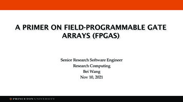
Field Programmable Gate ArraysTypical Complexity 5M – 1B transistorsFPGAs3
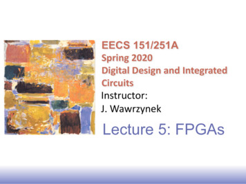
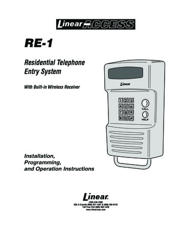
Basic FPGA Operation Writing configuration memory defines system function– Input/Output Cells– Logic in PLBs– Connections between PLBs& I/O cells Changing configurationmemory data changessystem function– Can change at anytime– Even while system functionis in 010101010010010014
5FPGAs
6FPGAs
Ranges of ResourcesFPGA LargeFPGAPLBs per FPGA25625,920LUTs and flip-flops per PLB18Wire segments per PLB45406PIPs per PLB1393,462Bits per memory core12836,864Memory cores per FPGA16576DSP cores0512Input/output cells621,200Configuration memory bits42,10479,704,832FPGAs7
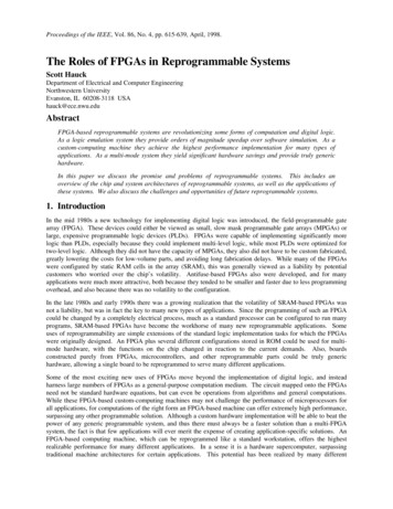
Programmable ASIC logic cells Xilinx : “configurable logic block” (CLB) contains– SRAM lookup tables (LUTs) to implement combinational logic– D flip flops– Multiplexers to establish paths in the CLB Actel “ACT” : multiplexers implement logic Altera “Flex” : similar to Xilinx CLB Altera “MAX” : PALs implement logic8FPGAs
Mux-based logic blocks in FPGAsText Figure 3.339FPGAs
Actel ACT architecture (Fig. 5.1)(mux-based logic modules)ACT 1 logic modulePass transistorimplementation10FPGAs
Xilinx FPGA families (2015)Digikey.com (4/03/18):Spartan-3A XC3S50A: 8.05Spartan-6 XC6SLX4: 11.48Artix-7 XC7A100T: 136.50Kinetix-7 XC7K70T: 139.65Virtex7 XC7V1140T-G2FLG1925E: 32,815.17FPGAs11
Xilinx FPGAs Virtex and Spartan 2– Array of 96 to 6,144 PLBs 4 LUTs/RAMs (4-input)4 FF/latches– 4 to 32 4K-bit dual-port RAMs Virtex II, Virtex II Pro– Array of 352 to 11,204 PLBs 8 LUTs/RAMs (4-input)8 FF/latchesSpecial coresI/O cellsRoutingPLBs– 12 to 444 18K-bit dual-port RAMs– 12 to 444 18 18-bit multipliers– 0 to 2 PowerPC processor coresPC Virtex 4PC– Array of 1,536 to 22,272 PLBs 4 LUTs/RAMs (4-input)4 LUTs (4-input)8 FF/latches– 48 to 552 18K-bit dual-port RAMs Spartan 3 Also operate as FIFOs– 32 to 512 DSP cores include:– 0 to 2 PowerPC processor coresFPGAsArray of 192 to 8,320 PLBs 4 LUTs/RAMs (4-input)4 LUTs (4-input)8 FF/latches4 to 104 18K-bit dual-port RAMs4 to 104 18 18-bit multipliers12
Xilinx 7 Series Families13FPGAs
Xilinx Artix-7 Family14FPGAs
Xilinx “UltraScale” FamilyKintex and Virtex UltraScale and UltraScale 15FPGAs
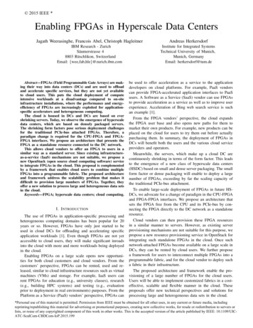
Xilinx: Basic CLB Architecture Look-up Table (LUT) implements truth table Memory elements:– Flip-flop/latch– Some FPGAs - LUTs can also implement small RAMs Carry & control logic implements fast adders/subtractorscarry outInput[1:4]4LUT/RAMControlCarry &ControlLogicclock, enable, set/reset3FPGAscarry inFlip-flop/LatchOutputQ output16
Combinational Logic FunctionsA Gates are combined to createcomplex circuits Multiplexer exampleSZB– If S 0, Z A– If S 1, Z B– Very common digital circuit– Heavily used in FPGAs S input controlled byconfiguration memory bit We’ll see it againFPGAsTruth tableSAB Z000 0001 0010 1011 1100 0101 1110 0111 1Logic symbolAB0Z10S117
Look-up TablesMultiplexer Recall multiplexerexample Configuration memoryholds outputs for truthtable Internal signalsconnect to controlsignals of multiplexersto select value of truthtable for any giveninput h tableSAB Z000 0001 0010 1011 1100 0101 1110 0111 118
Look-up Table Based RAMs Functions of more variables than LUT inputsf(a1,a0,b1,b0) a1f(1,a0,b1,b0) a1’f(0,a0,b1,b0)FPGAs
Look-up Table Based RAMs Artix-7 6-input LUTs can be partitioned into two 5-input LUTsFPGAs
Look-up Table Based RAMsData In Normal LUT mode performsread operations00ck1010In0In1In2 Small RAMs but can becombined for larger RAMsAddress Decoder Address decoder with writeenable generates clocksignals to latches for ableck600ck71121In0FPGAsZIn1In2
A Simple CLB Two 3-input LUTs– Can implement any4-inputcombinational logicfunctionC7D2-0 1 flip-flop– Programmable: Active levels Clock edge Set/reset 22 configurationmemory bits– 8 per LUT C0-7 S0-7LUT3C4C3C2C1C0111 110 101 100 011 010 001 000outSmuxSOmux0 Sout101LUT S8x1D301CB5CEmuxCB3Clock EnableSRmux01CB4FFSet/ResetClockCB– 6 controls C5CoutLUT C8x1D2-0C6CB0CB0-7FPGAsCB1CB2 ConfigurationMemory Bit22
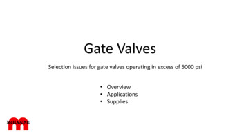
Example CLBArtix-7 SLICEL (1/2 shown)Four 6-input Look-Up Tables (LUTs) ––Any combinational logic function of up to 6 inputsSLICEM LUT can function as small RAM (16x1-bit) orshift register (up to 16-bit) Eight D flip-flops––Programmable as latchesProgrammable clock edge, clock enable, set/reset–––Fast carry for addersMUXs for Shannon expansionAnd moreExtra logicFPGAs23
Synchronous sequential circuitFPGAs24
CLBs and Slices in rows/columnsFPGAs25
Using lookup-table (LUT) programmable logic26FPGAs
Functions of more variablesthan # of LUT inputsShannon’s Expansion Theorem (partition into smaller functions):𝑍𝑍 𝑎𝑎, 𝑏𝑏, 𝑐𝑐, 𝑑𝑑, 𝑒𝑒, 𝑓𝑓 𝑎𝑎 𝑍𝑍 0, 𝑏𝑏, 𝑐𝑐, 𝑑𝑑, 𝑒𝑒, 𝑓𝑓 𝑎𝑎 𝑍𝑍 1, 𝑏𝑏, 𝑐𝑐, 𝑑𝑑, 𝑒𝑒, 𝑓𝑓 𝑎𝑎𝑍𝑍0 𝑎𝑎𝑍𝑍1FPGAs27
𝑀𝑀 𝑆𝑆1 𝑆𝑆0 𝐼𝐼0 𝑆𝑆1 𝑆𝑆0 𝐼𝐼1 𝑆𝑆1 𝑆𝑆0 𝐼𝐼2 𝑆𝑆1 𝑆𝑆0 𝐼𝐼3M1M228FPGAs
29FPGAs
Fig. 6-13 Simplified Spartan andVirtex Slice30FPGAs
Input/Output Cells Signals between I/O pins and the logic array31FPGAs
Input/Output Cells Bi-directional buffers– Programmable for input or output– Tri-state control for bi-directional operationTri-state Control– Flip-flops/latches for improved timing Set-up and hold times Clock-to-output delay– Pull-up/down resistorsto/frominternalroutingresourcesOutput DataPadInput Data Routing resources– Connections to core of array Programmable I/O voltage & current levels32FPGAs
Detailed I/O Cell33FPGAs
Interconnect Network Wire segments of varying length– xN N CLBs in length Wire A1, 2, 4, and 6 are most common– xH half the array in lengthconfigbit– xL length of full arrayWire B Programmable Interconnect Points (PIPs) Also known as Configurable Interconnect Points (CIPs)– Transmission gate connects to 2 wire segments– Controlled by configuration memory bit 0 wires disconnected 1 wires connected34FPGAs
Xilinxinterconnectstructures35FPGAs
PIPs Break-point PIP– Connect or isolate 2 wire segments Cross-point PIP– Turn corners Multiplexer PIP– Directional and buffered– Select 1-of-N inputs for output Decoded MUX PIP – N config bits select from 2N inputs Non-decoded MUX PIP – 1 config bit per input Compound cross-point PIP– Collection of 6 break-point PIPs Can route to two isolated signal netsFPGAs36
Switch box Connects CLB to the “routing fabric”37FPGAs
Spartan 3 Routing Resourcesswitch matrixover 2,400 PIPsmostly MUX PIPsPLB consistsof 4 slicesx6 wiresegmentsx2 wiresegmentsxH & xL wiresegmentsover 450total wiresegmentsin PLB38FPGAs
39FPGAs
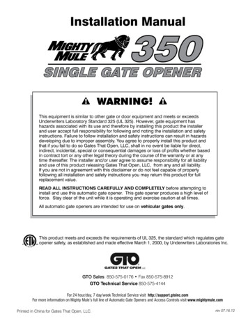
Fully routed O2.I1Net S2END0(5,6)(6,6)(7,6)(8,6)S2.I1Net N2E2BEG2E2END2Net N1: Site S1 output pin O1 connects to input pin I1 on site S3Net N2: Site S1 output pin O2 connects to input pin I1 on site S2Black “dots” are routing pipsPredefined connections exist between switch boxes40
ELEC 4200 Lab 0 in Spartan 641FPGAs
Lab 0 in Spartan 6(routing details)42FPGAs
Ex: modulo7 counter (device xc6slx25t)INTsNetsCLBsIO PadsFPGAs43
FPGA clock regionsLogicResourcesLogicResourcesClock gicResourcesClock RegionLogicResourcesFPGAsLogicResourcesCenter ClockColumn(s)Clock Routing44
Spartan 6 clock tree exampleMain vertical spineBUFG“Folded” vertical spine(one each in top and bottom half)CLKC tileDistribution wire incenter of clock regionClock to INTsin one column47BUFH8INTCLEXM10FPGAs45
7 Series FPGA high-level clock architecture view46FPGAs
Basic view of a clock region47FPGAs
Clock management tile (CMT)Mixed-mode clock manager (MMCM)MMCMOutputsClockSourcesMMCM Outputs frequency divided, phase shifted, invertedUp to 24 CMTs per Series 7 deviceFPGAs48
Clock management tile (CMT)Phase-locked loop (PLL)PLL frequency synthesizer using a voltage-controlled oscillator (VCO)PLLOutputsClockSources49FPGAs
Spartan 6 global clock sourcesFrom DCM/PLLand fabricBUFG controlsfrom fabricFrom left edgeGlobal clockpadsFrom DCM/PLLand fabricFrom top edge global clock padsBUFGs Vertical spinesClock createdby MIPS controllogicSwitch BoxFrom rightedge globalclock padsFrom clockinput pad50From bottom edge global clock padsFPGAs
Specialized “hard “ cores– RAMs – single-port, dual-port, FIFOs 128 bits to 36K bits per RAM 4 to 575 RAM cores per FPGA– DSPs – 18x18-bit multiplier, 48-bit accumulator, etc. up to 512 per FPGA– Microprocessors and/or microcontrollers Up to 2 per FPGA (hard core processor) Support soft core processors– Synthesized from HDL into programmable resources– Communication functions Gigabit transceivers Ethernet MAC PCE Express busFPGAs51
FPGA Architectures 4000/Spartan– NxN array of unit cells Unit cell CLB routing– Special routing along center axes– I/O cells around perimeter Virtex/Spartan-2– MxN array of unit cells– Added block 4K RAMs at edges Virtex-2/Spartan-3– Block 18K RAMs in array– Added 18x18 multipliers with each RAM– Added PowerPCs in Virtex-2 Pro Virtex-4/Virtex-5PCPC– Added 48-bit DSP cores w/multipliers– I/O cells along columns for BGA52PCFPGAsPC
Xilinx Virtex-4 FPGAs Configuration memory: 4.7M to50.8M bits of RAM PLBs: 1,536 to 22,272– 4 slices per PLB 2 LUTs & 2 FFs per slice 2 slices can operate as RAMs/SRsPC Block RAMs: 48 to 552 18K-bit dualport RAMs– Also operate as FIFOs DSP cores: 32 to 512, each includes:PC– 18x18-bit multiplier– 48-bit adder & accumulator Up to 2 PowerPC processorsFPGAs53
Block RAMs 36 Kbit dual-port RAM Each port independently configurable:– IK words x 36 bits 32 data bits 4 parity bits– 2K words x 18 bits 16 data bits 2 parity bits– 4K words x 9 bits 8 data bits 1 parity bit– 8K words x 4 bits (no parity)– 16K words x 2 bits (no parity)– 32K words x 1 bit (no parity) Each port has independentlyprogrammable– clock edge, active levels for write enable,RAM enable, resetFPGAs54
55FPGAs
ROMContents656FPGAs
Distributed RAM657FPGAs
658FPGAs
59Refer to the “synthesis guide” for recommended HDL formsFPGAs
DSP Blocks: Multiplier and Support Circuits60FPGAs
7 Series DSP48E1 DSP slice 25 18 two’s-complement multiplier: Dynamic bypass 48-bit accumulator: Can be used as a synchronous up/down counter Power-saving pre-adder: Optimizes symmetrical filter applications andreduces DSP slice requirementsFPGAs61
DSP48E1 slice details62FPGAs
Embedded Processors Hard core Soft core Faster Fixed position Few devices Virtex-4 Processors: Slower Can be placed anywhere Applicable to many devicesARM Processorsin 7 SeriesEmbedded Core Max ClockBlockSlicesPLBsProcessor Type FrequencyRAMsPowerPC Hard 222 MHz 1000 2509Microblaze Soft180 MHz 940 2359PicoblazeSoft221 MHz 333 843PicoblazeSoft233 MHz 274 Blaze63
Xilinx Zynq SoC devicesZynq-7000 SoC: Dual-core ARM Cortex-A9 MPCore (up to 1GHz)Zynq UltraScale MPSoC: Quad-core ARM Cortex-A53 MP (up to 1.5 GHz) Dual-core ARM Cortex-R5 MPCore (up to 600MHz) GPY ARM Mali-400 MP2 (up to 667MHz)PL ProgrammableLogic64FPGAs
Zynq-7000 SoC Features (1)Processing System Resources65Continued next slideFPGAs
Zynq-7000 SoC Features (2)Programmable Logic Resources66FPGAs
67FPGAs
Zynq-7000 SoC Processor System68FPGAs
69FPGAs
Zynq-7000 SoC Logic FabricSeries-7 CLBs, IOBs, etc. (as in Artix-7)70FPGAs
Configuration Interfaces Master – FPGA retrieves its own configuration from ROM after power-up– Serial or Parallel optionsclockPROM withConfigurationDatadata outCCLKCCLKFPGA inMasterModeDinDout Slave – FPGA configured by external source (i.e., a µP)–––CCLKFPGA inSlaveModeDinDoutFPGA inSlaveModeDinDoutSerial or Parallel optionsUsed for dynamic reconfigurationCan also read configuration memory contents Boundary Scan Interface–––4-wire IEEE standard serial interface for testingWrite and read access to configuration memory Not available in all FPGAs Used for dynamic partial reconfigurationInterfaces to FPGA core Not available in all FPGAs Connections between Boundary Scan Interface and internal routing network and PLBs (Xilinxprovides 2-4 of these ports) Other configuration interfaces in some FPGAsFPGAs71
Slave configuration modes72FPGAs
Nexys4 DDR configuration optionsArtix-7 100T bitstream is typically 30,606,304 bits2131. USB-JTAG : PC connection via USB or JTAG2. Master SPI: Program from “quad mode” flash memory (x1, x2, x4 width)3. USB/SD: Program from micro SD card or USB memory stickFPGAs73
FPGA Configuration Memory PLB addressable– Good for partial reconfiguration– X-Y coordinates of PLB location to be written Requires tag to identify which resources will be configured Frame addressable– Vertical or horizontal frame– Access to all PLBs in frame Only portion of logic and routing resources accessible in a given frame Many frames to configure PLBs–Major address for column, minor address for frameHybrid, i.e.:Virtex-4Virtex-5Virtex-6FPGAs74
Daisy Chain ConfigurationEPROMConfigurationBits75FPGAs
Xilinx Configuration Interface Pins76FPGAs
Configuration Techniques Full configuration & readback– Simple configuration interface Internal automatic calculation of frame address– Long download time for large FPGAs Partial reconfiguration & readback– Only change portions of configuration memory with respect to referencedesign Reduces download time for reconfiguration– Requires more complicated interface Command Register (CMR) Frame Length Register (FLR) Frame Address Register (FAR) Frame Data Register– Input (FDRI) – for download– Output (FDRO) – for readback (note separate access)FPGAs77
Full Configuration Example Dummy Word 0xFFFFFFFF Synchronize Word 0xAA995566 CMD Write 0x30008001– Reset CRC 0x00000007 FLR Write 0x30016001– FLR 0x00000024– Frame length 37 words 1,184 bits 32 bits/word COR Write 0x30012001– COR Write 0x00003FE5 IDCODE Write 0x3001C001– Device ID 0x0140D093 (3S50) MASK Write 0x3000C001– MASK 0x00000000 CMD Write 0x30008001– Switch CCLK 0x00000009 FAR Write 0x30002001– FAR 0x00000000 (full config) CMD Write 0x30008001– Write CFG 0x00000001 FDRI Write 0x30004000– # words to write 0x50003555FPGAsXilinx ASCII BitstreamCreated by Bitstream I.32Design Date:Tue Sep 04 15:50:09 10101start of actual configuration data78
GATE ARRAYS (FPGAS) Roth Text: Chapter 3 (section 3.4) Chapter 6 . Nelson Text: Chapter 11. FPGAs 1. Programmable logic taxonomy FPGAs 2 Lab Device. Field Programmable Gate Arrays FPGAs Typical Complexity 5M - 1B transistors 3. Basic FPGA Operation Writing configuration memory