Transcription
Shortcut Key Guide
TABLE OF CONTENTSOne Key ShortcutsKeyboard Diagram. 3Printable Keyboard Stickers. 14Multi-Character CommandAliases by CategoryAnnotation. 6Keyboard ShortcutCommands by CategoryAssembly. 6Assembly. 4Dynamic Simulation. 8Drawing Manager. 4Frame Analysis. 8-9General. 4Mold Design. 9-10Part. 4Part. 10Placed Features. 4Placed Features. 11Sketch. 5Presentation. 11Tools. 5Sheet Metal. 11View. 5Sketch. 11-12Work Features. 5Sketch Features. 12Cable & Harness. 6-7Dimension. 7Drawing Manager. 8Stress Analysis. 12-13Tools. 13Tube & Pipe. 13View. 13NOTE: To enable the use of multi-character command aliases in Inventor, makesure the “Use default multi-character Command Aliases” option is checked.To access this, select Tools tab Options panel Customize, and click theKeyboard tab.2
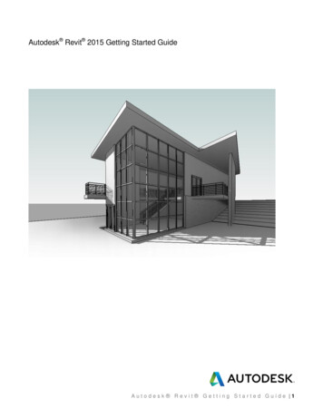
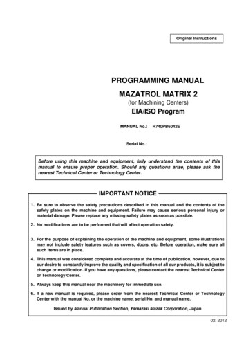
CANCELHELP PAN ZOOM SELECTED ROTATEPREVIOUS VIEWHOME VIEWSLICE GRAPHICSSHOW ALLCONSTRAINTS HIDE ALLCONSTRAINTSSKETCH VISIBILITYONE KEY SHORTCUTS [SEE PRINTABLE KEYBOARD STICKERS ON PAGE 14]EscF1F2F3F4F5F6F7F8F9F10 !1TabCaps Lock@# % &*()234567890QWERYUIOZShiftCtrlSAStartDXFCGVAlt EQUAL / Constrains curves to equalradius or length.; GROUNDED WORK POINT / Creates agrounded work point and activates the3D Move/Rotate tool./TWORK AXIS / Creates a new work axis.HBJNKM {[GROUNDEDWORK POINT;WORK POINTWORK AXIS./AltPrtScnSysRqBackspaceEQUALPL ,—-F11 F12HomeInsertEnterDelete]PauseBreakEndZOOMSELECTED \WORKPLANE“‘ScrLKPageUpLOOK ATDELETEPageDownShiftCtrlDELETE DELETE / Removes the selected itemfrom the model or drawing.END ZOOM SELECTED / Zooms in on aspecifically selected item.ESCCANCEL / Closes the active tool.] WORK PLANE / Creates a new workplane.HOME ZOOM ALL / Zooms to the extents of allobjects in the graphics window. WORK POINT / Creates a new workpoint.PAGE UPLOOK AT / Looks at a selected entity.3
KEYBOARD SHORTCUT COMMANDSAssemblyGeneralALT-DRAG MOUSE MATE CONSTRAINT / Applies a mateconstraint.CTRL-A SELECT ALL / Selects everything on thescreen.CTRL-H REPLACE COMPONENT / Replacesone assembly component with anothercomponent.CTRL-CSHIFT-TAB PROMOTE / Removes a part from asubassembly and makes it an individualpart in the parent assembly.Drawing ManagerCTRL-SHIFT-N NEW SHEET / Inserts a new drawingsheet.CTRL-SHIFT-T LEADER TEXT / Adds notes with leaderlines to a drawing.COPY / Copies selected items.CTRL-F FIND / Presents the Find Part Sketchesdialog box in part files; opens the FindAssembly Components dialog box inassembly files.CTRL-NNEW / Displays the New File dialog box.CTRL-O OPEN / Displays the Open dialog box,to open an existing file.CTRL-PCTRL-SSAVE / Displays the Save As dialog box.CUT / Cuts selected items.CTRL-Y REDO / Redoes previously undonecommands.CTRL-ZPartCTRL-SHIFT-KCHAMFER / Activates the Chamfer tool.CTRL-SHIFT-LLOFT / Activates the Loft tool.CTRL-SHIFT-MMIRROR / Activates the Mirror tool.PRINT / Displays the Print dialog box.CTRL-V PASTE / Pastes a cut or copied item fromone location to another.CTRL-XSHIFT-RIGHT MOUSE CLICK SELECT / Activates the select commandmenu.Placed FeaturesCTRL-SHIFT-O CIRCULAR PATTERN / Opens the CircularPattern dialog box.CTRL-SHIFT-R RECTANGULAR PATTERN / Opens theRectangular Pattern dialog box.CTRL-SHIFT-SSWEEP / Activates the Sweep tool.UNDO / Undoes the effects of commands.DELETE DELETE / Removes the selected item fromthe model or drawing.QUIT EXIT / Quits the application; prompts tosave documents.4
KEYBOARD SHORTCUT COMMANDSSketchView EQUAL / Constrains curves to equal radiusor length.ALT-. USER WORK POINTS VISIBILITY / Makeswork points visible.F5 PREVIOUS VIEW / Returns to the lastdisplay.F7 SLICE GRAPHICS / Slices away temporarilythe portion of the model that obscures theplane.ALT-] USER WORK PLANE VISIBILITY / Makeswork planes visible.F6 HOME VIEW / Rotates objects in thegraphics window into an isometricorientation.F8 SHOW ALL CONSTRAINTS / Displays allconstraints.F9 HIDE ALL CONSTRAINTS / Hides Allconstraints.ALT-/ USER WORK AXES VISIBILITY / Makeswork axes visible.CTRL-. ORIGIN POINTS VISIBILITY / Makes thedefault origin points visible.CTRL-] ORIGIN PLANE VISIBILITY / Makes thedefault origin planes visible.F10 SKETCH VISIBILITY / Makes sketchesvisible.HOME ZOOM ALL / Zooms to the extents of allobjects in the graphics window.PAGE UPLOOK AT / Looks at a selected entity.ToolsCTRL-/ ORIGIN AXES VISIBILITY / Makes thedefault origin axes visible.SHIFT-F3 ZOOM WINDOW / Zooms to the area youdefine with a window.ALT-F8CTRL-0 TOGGLE SCREEN / Toggles screen.SHIFT-F5NEXT VIEW / Advances to the next view.MACROS / Opens the Macros dialog box.ALT-F11 VISUAL BASIC EDITOR / Launches theMicrosoft Visual Basic Editor.ESCCANCEL / Closes the active tool.F1HELP / Opens the Inventor help files.CTRL-SHIFT-E DEGREES OF FREEDOM / Displaysdegrees of freedom.CTRL-SHIFT-Q IMATE GLYPH / Activates the iMate Glyphtool.CTRL-W STEERING WHEELS / Displays the SteeringWheel view tool.END ZOOM SELECTED / Zooms in on aspecifically selected item.F2 PAN / Views areas of the graphicswindow. (You must hold the [F2] keydown.)F3 ZOOM SELECTED / Realtime zoom in andout of the graphics window. (You musthold the [F3] key down.)F4 ROTATE / Rotates objects in the graphicswindow.SHIFT-MIDDLE MOUSE CLICKROTATE / Rotates a model.Work Features; GROUNDED WORK POINT / Creates agrounded work point and activates the 3DMove/Rotate tool./WORK AXIS / Creates a new work axis.] WORK PLANE / Creates a new workplane. WORK POINT / Creates a new workpoint.5
MULTI-CHARACTER COMMAND ALIASESAnnotationBA AUTO BALLOON / Creates one or moreitem balloons used to identify componentsin drawing views.CAT CATERPILLAR / Adds a weld caterpillarannotation.CB CENTERLINE BISECTOR / Adds acenterline bisector.RTB REVISION TABLE / Creates a revisiontable.ST SURFACE TEXTURE SYMBOL / Adds asurface texture symbol.SY SYMBOLS / Adds sketched symbols to adrawing sheet.CL CENTERLINE / Adds a centerline.T TEXT / Activates the text tool in a drawingfile.CM CENTER MARK / Adds a center mark.TB TABLE / Creates a table.DI DATUM IDENTIFIER SYMBOL / Adds adatum identifier symbol.WS WELDING SYMBOL / Provides annotationand acts as a grouping mechanism byreferencing multiple beads with a singlewelding symbol.EF END FILL / Adds a weld end fill annotationin a drawing view or on a 3D weld beadto represent the hatched or filled regionindicating the end of a weld bead.F FEATURE CONTROL FRAME / Places afeature control frame in drawing files.FI FEATURE IDENTIFIER SYMBOL / Adds afeature identifier symbol.HTF HOLE TABLE-FEATURES / Selects featureset (all punch center instances from asingle feature).AssemblyC CONSTRAINTS / Adds an assemblyconstraint.CO COPY COMPONENTS / Creates a copy ofthe component.HTS HOLE TABLE-SELECTION / Selectsrecovered punch centers individually.G ROTATE COMPONENT / Activates theRotate tool.HTV HOLE TABLE-VIEW / Adds a hole table toa view.IA ANALYZE INTERFERENCE / Analyzesassemblies for interference.LE LEADER TEXT / Adds notes with leaderlines to a drawing.MI MIRROR COMPONENTS / Creates amirror component.PL PARTS LIST / Creates a parts list.N CREATE COMPONENT / Displays theCreate In-Place Component dialog box.RT REVISION TAG / Adds revision tags to adrawing.PC PATTERN COMPONENT / Selects oneor more components to include in thepattern.RA REPLACE ALL / Replaces all occurrencesof the component in the current assembly.V MOVE COMPONENT / Activates theMove Component command.Cable & HarnessAR AUTOMATIC ROUTE / Automaticallyroutes one or more selected wires intosegments based on the shortest paththrough the network and the segmentopening that is closest to the wire startand endpoints.BR CHECK BEND RADIUS / Checks for bendsthat do not meet the specified minimumbend radius on segments, and routed andunrouted wires and cables in the activeharness assembly.BS BROKEN SKETCH ENTITY / Sets thestart point and endpoint for the length toremove from the cable, wire, or segment.CA CONNECTOR AUTHORING / Adds Cableand Harness-specific data to complete thedefinition of connectors for use in Cableand Harness.CC CREATE CABLE / Creates a cablecontaining multiple wires that areconnected or terminated to selected pinswithin a harness assembly.P PLACE COMPONENT / Places acomponent in the current assembly.6
MULTI-CHARACTER COMMAND ALIASESCable & HarnessCF CREATE FOLD / Creates fold.CR CREATE RIBBON CABLE / Creates aribbon cable between a start and endconnector.CS CREATE SEGMENT / Creates a harnesssegment.CV PLACE CONNECTOR VIEWS / Placesconnector views.CW CREATE WIRE / Creates a wire betweenselected pins within a harness assembly.EEDIT / Edits nailboard sketch.EH EXPORT HARNESS DATA / Exportsharness data .F FAN IN / Collapses wire stubs on top ofone another to reduce the detail or clutterin nailboard documentation.FO FAN OUT / Equally distributes wire stubsabout the endpoint of a segment usingthe specified angle and sorting direction.HA CREATE HARNESS / Adds the harnesssubassembly to an assembly file with thespecified name and location, and displaysthe Cable and Harness tab.HD HARNESS DIMENSION / Adds a driven,aligned dimension between 2 points.HP HARNESS PROPERTIES / Customproperties of harness components.IH IMPORT HARNESS DATA / Importsharness data.DimensionL CABLE & HARNESS LIBRARY / Adds newlibrary definitions, and modifies, copies,and deletes existing library definitions forharness objects such as wires, cables, rawribbon cables, and virtual parts.BD BASELINE DIMENSION / Adds baselinedimensions.NB NAILBOARD / Specifies the harnessassembly and setup to create or edit anailboard view.CN CHAMFER NOTE / Adds a chamfer noteto a drawing view.P PIVOT / Fixes segment points so you candrag the selected segment relative to thatfixed point.*P PLACE PIN / Places a pin.*PD PROPERTY DISPLAY / Displays propertiesfor the selected objects.PG PLACE PIN GROUP / Automatically placesmultiple pins with the specified naming,configuration, and orientation on a part.BN BEND NOTES / Creates or edits a bendnote.D GENERAL DIMENSION / Adds adimension to a sketch or drawing.HN HOLE/THREAD NOTES / Adds a hole orthread note with a leader line.O ORDINATE DIMENSION SET / Activatesthe Ordinate Dimension Set command.OD ORDINATE DIMENSION / Adds anordinate dimension.PNPUNCH NOTES / Creates a punch note.RG REPORT / Process reports for the activeharness assembly.RH REVIEW HARNESS DATA / Reviewsharness data.RT ROUTE / Routes cables and wiresmanually.RW RECONNECT WIRE PINS / Reconnectswire pins.SP CREATE SPLICE / Creates a splice.TB TABLE / Creates a table.U UNROUTE / Unroutes selected wires fromselected segments.V ASSIGN VIRTUAL PARTS / Assigns virtualparts.*NOTE: The same alias can perform different commands depending on the design environment and object you are working on.7
MULTI-CHARACTER COMMAND ALIASESDrawing ManagerDynamic SimulationFrame AnalysisAV AUXILIARY VIEW / Places an auxiliaryview by projecting from an edge or line ina parent view.AVIA ANIMATE RESULTS / Animates theselected simulation results.B BALLOON, BOM / Activates the Balloontool or displays the BOM Properties dialogbox, depending on the work environment.BVBASE VIEW / Creates a base view.BRV BREAK / Creates a broken, foreshortenedview.BO BREAK OUT / Removes a defined areaof material to expose obscured parts orfeatures in an existing drawing view.CR CROP / Use to set boundary typeand visibility of crop cut lines for cropoperations.DV DETAIL VIEW / Provides circular andrectangular shapes of detail profile.PV PROJECTED VIEW / Creates a projectedview.RD RETRIEVE DIMENSIONS / Retrieves modeldimensions in a drawing.SVSECTION VIEW / Creates a section view.PUBLISH MOVIE / Creates AVI animati
F1 / Opens the Inventor help files.HELP View ALT-. USER WORK POINTS VISIBILITY / Makes work points visible. ALT-] USER WORK PLANE VISIBILITY / Makes work planes visible. ALT-/ USER WORK AXES VISIBILITY / Makes work axes visible. CTRL-. ORIGIN POINTS VISIBILITY / Makes the default origin points visible. CTRL-] ORIGIN PLANE VISIBILITY / Makes the default origin planes visible.